IBOB Fan Header Modification Procedure - CASPER
IBOB Fan Header Modification Procedure - CASPER
IBOB Fan Header Modification Procedure - CASPER

Create successful ePaper yourself
Turn your PDF publications into a flip-book with our unique Google optimized e-Paper software.
<strong>IBOB</strong> <strong>Fan</strong> <strong>Header</strong> <strong>Modification</strong> <strong>Procedure</strong><br />
Author: Henry Chen<br />
September 17, 2007 (v1.0)<br />
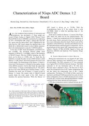
<strong>IBOB</strong> boards were designed for high-density installation in a card cage or similar mounting<br />
solution with cooling fans. As such, the design relies on external cooling, and has no provision to<br />
attach a fan to cool the Xilinx FPGA. Forced-air cooling of the FPGA heatsink is strongly<br />
recommended, and is particularly necessary for designs that highly pack the FPGA or clock it at<br />
high rates. This document describes the procedure for modifying an <strong>IBOB</strong> board to provide a<br />
header from which to power a 5V DC fan.<br />
To get power for the fan, the 5V power-on LED must be forfeited. This LED is one of the only<br />
points on the board from which the 5V input can be accessed before it is regulated into the other<br />
board voltages. The LED is powered from 5V through a series resistor, so the modification will<br />
involve removing both the LED and the resistor, and bridging the header to a 5V pad.<br />
The LED to be removed is D11, located at the upper-left corner of the board when viewed with<br />
the orientation shown below. It is next to the power input connector of the board.<br />
<strong>IBOB</strong> <strong>Fan</strong> <strong>Header</strong> <strong>Modification</strong> 1<br />
(v1.0) September 17, 2007
Remove the LED. Its through-hole footprint is suitable for a 0.100” header.<br />
On the underside of the board in the same vicinity is resistor R64, which also needs to be<br />
removed. R64 is connected in series between the 5V plane and the LED.<br />
<strong>IBOB</strong> <strong>Fan</strong> <strong>Header</strong> <strong>Modification</strong> 2<br />
(v1.0) September 17, 2007
<strong>IBOB</strong> <strong>Fan</strong> <strong>Header</strong> <strong>Modification</strong> 3<br />
(v1.0) September 17, 2007
Once R64 has been removed:<br />
<strong>IBOB</strong> <strong>Fan</strong> <strong>Header</strong> <strong>Modification</strong> 4<br />
(v1.0) September 17, 2007
Insert a 1×2 or 1×3 0.100” header where the LED used to be populated. A 3-pin header is<br />
recommended, as it provides additional mechanical stability for standard 3-pin fan connectors. If<br />
a 3-pin header is used, clip the unused pin tail.<br />
Once the header is installed, connect 5V to the header by shorting across the pads of R64 with<br />
solder or rework wire.<br />
<strong>IBOB</strong> <strong>Fan</strong> <strong>Header</strong> <strong>Modification</strong> 5<br />
(v1.0) September 17, 2007
Once the board modification is complete, a 5V DC fan can be attached to the <strong>IBOB</strong>. A<br />
Panasonic/NMB FBK04F05H is recommended.<br />
<strong>IBOB</strong> <strong>Fan</strong> <strong>Header</strong> <strong>Modification</strong> 6<br />
(v1.0) September 17, 2007