Megaflux Series Thin Ring Torque Motors - Grp6.com
Megaflux Series Thin Ring Torque Motors - Grp6.com
Megaflux Series Thin Ring Torque Motors - Grp6.com
Create successful ePaper yourself
Turn your PDF publications into a flip-book with our unique Google optimized e-Paper software.
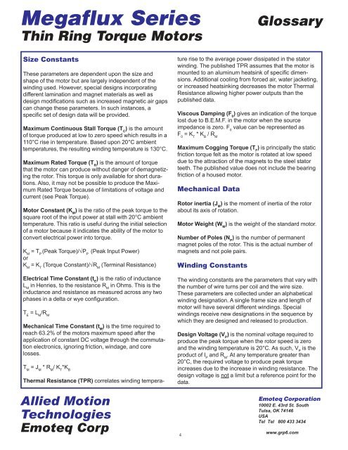
<strong>Megaflux</strong> <strong>Series</strong><br />
<strong>Thin</strong> <strong>Ring</strong> <strong>Torque</strong> <strong>Motors</strong><br />
Glossary<br />
Size Constants<br />
These parameters are dependent upon the size and<br />
shape of the motor but are largely independent of the<br />
winding used. However, special designs incorporating<br />
different lamination and magnet materials as well as<br />
design modifications such as increased magnetic air gaps<br />
can change these parameters. In such instances, a<br />
specific set of design data will be provided.<br />
Maximum Continuous Stall <strong>Torque</strong> (T C<br />
) is the amount<br />
of torque produced at low to zero speed which results in a<br />
110°C rise in temperature. Based upon 20°C ambient<br />
temperatures, the resulting winding temperature is 130°C.<br />
Maximum Rated <strong>Torque</strong> (T R<br />
) is the amount of torque<br />
that the motor can produce without danger of demagnetizing<br />
the rotor. This torque is only available for short durations.<br />
Also, it may not be possible to produce the Maximum<br />
Rated <strong>Torque</strong> because of limitations of voltage and<br />
current (see Peak <strong>Torque</strong>).<br />
Motor Constant (K M<br />
) is the ratio of the peak torque to the<br />
square root of the input power at stall with 20°C ambient<br />
temperature. This ratio is useful during the initial selection<br />
of a motor because it indicates the ability of the motor to<br />
convert electrical power into torque.<br />
K M<br />
= T P<br />
(Peak <strong>Torque</strong>)/√P P<br />
(Peak Input Power)<br />
or<br />
K M<br />
= K T<br />
(<strong>Torque</strong> Constant)/√R M<br />
(Terminal Resistance)<br />
Electrical Time Constant (t E<br />
) is the ratio of inductance<br />
L M<br />
in Henries, to the resistance R M<br />
in Ohms. This is the<br />
inductance and resistance as measured across any two<br />
phases in a delta or wye configuration.<br />
T E<br />
= L M<br />
/R M<br />
Mechanical Time Constant (t M<br />
) is the time required to<br />
reach 63.2% of the motors maximum speed after the<br />
application of constant DC voltage through the commutation<br />
electronics, ignoring friction, windage, and core<br />
losses.<br />
T M<br />
= J M<br />
* R M<br />
/ K T<br />
*K B<br />
Thermal Resistance (TPR) correlates winding temperature<br />
rise to the average power dissipated in the stator<br />
winding. The published TPR assumes that the motor is<br />
mounted to an aluminum heatsink of specific dimensions.<br />
Additional cooling from forced air, water jacketing,<br />
or increased heatsinking decreases the motor Thermal<br />
Resistance allowing higher power outputs than the<br />
published data.<br />
Viscous Damping (F 0<br />
) gives an indication of the torque<br />
lost due to B.E.M.F. in the motor when the source<br />
impedance is zero. F 0<br />
value can be represented as<br />
F 0<br />
= K T<br />
* K B<br />
/ R M<br />
Maximum Cogging <strong>Torque</strong> (T F<br />
) is principally the static<br />
friction torque felt as the motor is rotated at low speed<br />
due to the attraction of the magnets to the steel stator<br />
teeth. The published value does not include the bearing<br />
friction of a housed motor.<br />
Mechanical Data<br />
Rotor inertia (J M<br />
) is the moment of inertia of the rotor<br />
about its axis of rotation.<br />
Motor Weight (W M<br />
) is the weight of the standard motor.<br />
Number of Poles (N P<br />
) is the number of permanent<br />
magnet poles of the rotor. This is the actual number of<br />
magnets and not pole pairs.<br />
Winding Constants<br />
The winding constants are the parameters that vary with<br />
the number of wire turns per coil and the wire size.<br />
These parameters are collected under an alphabetical<br />
winding designation. A single frame size and length of<br />
motor will have several different windings. Special<br />
windings receive new designations in the sequence by<br />
which they are designed and released to production.<br />
Design Voltage (V P<br />
) is the nominal voltage required to<br />
produce the peak torque when the rotor speed is zero<br />
and the winding temperature is 20°C. As such, V P<br />
is the<br />
product of I P<br />
and R M<br />
. At any temperature greater than<br />
20°C, the required voltage to produce peak torque<br />
increases due to the increase in winding resistance. The<br />
design voltage is not a limit but a reference point for the<br />
data.<br />
Allied Motion<br />
Technologies<br />
Emoteq Corp<br />
4<br />
Emoteq Corporation<br />
10002 E. 43rd St. South<br />
Tulsa, OK 74146<br />
USA<br />
Tel Tel 800 433 3434<br />
www.grp6.com


