AS-700, AS-710
AS-700, AS-710
AS-700, AS-710

Create successful ePaper yourself
Turn your PDF publications into a flip-book with our unique Google optimized e-Paper software.
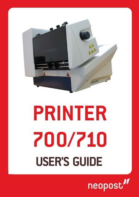
PRINTER<br />
<strong>700</strong>/<strong>710</strong><br />
USER'S GUIDE
Products presented in this guide are conform to<br />
requirements of directives nbr 73/23/CEE and<br />
89/336/CEE.<br />
Neopost has implemented a program for the<br />
recycling of worn machines and machines at the<br />
end of their lifetime. Contribute in a responsible<br />
way to the environmental protection by consulting<br />
your retailer internet site, or by contacting him.<br />
He will inform you of the collection and treatment<br />
processes of these machines.<br />
2
© Copyright 2007<br />
All rights reserved. This manual may not be reproduced in whole or in part, transferred,<br />
stored in a telemetry system or translated into any language, in whatsoever<br />
form, without prior written permission.<br />
The manufacturer assumes no liability for damages occurring as a result of misuse,<br />
repairs and modifications, which are carried out by unauthorized third parties. This<br />
manual has been prepared with great care. However, liability is excluded for any<br />
errors occurring in spite of such care.. In his commitment to continuous improvement,<br />
the manufacturer reserves the right to implement further technical and optical<br />
changes. The values herein provided are nominal values. Therefore, no legal<br />
claims may be raised in connection with this manual.<br />
The manufacturer cannot be held liable for damages or malfunctions caused by options<br />
or accessories, when these are not original products or when they have not<br />
been expressly approved by the manufacturer.<br />
Brand:<br />
HP is a registered brand name of Hewlett-Packard Corporation.<br />
Microsoft and Windows are registered brand names of Microsoft Corporation.<br />
3
Table of Contents<br />
Table of Contents<br />
1 Introduction<br />
1.1 Pictogram<br />
1.2 Notes for the Use of this Manual<br />
1.3 Important Terms and Abbreviations<br />
1.4 System requirements<br />
2 Safety Notes<br />
2.1 General Safety Notes<br />
2.2 Handling Ink Cartridges<br />
2.3 Location of the Printer<br />
2.4 Disposal<br />
3 Transport and Packaging<br />
3.1 Shipping<br />
3.2 Unpacking the Printer<br />
3.3 Assembly<br />
4 Printer Description<br />
4.1 Machine Overview<br />
4.2 Range of Application0<br />
4.3 Operation<br />
4.4 The Control Panel<br />
4.4.1 Keyboard Layout<br />
4.4.2 Key Combinations<br />
4.5 The Display<br />
4.5.1 Offline Mode<br />
4.5.2 Online Mode<br />
4.6 Brief Instructions<br />
5 Start-Up and Operation<br />
5.1 Setting Up and Connecting the Printer<br />
5.2 Installing the Driver<br />
4
5.3 Inserting the Ink Cartridge<br />
5.3.1 Correctly Inserting the Ink Cartridge<br />
5.3.2 Resetting the Ink Counter<br />
5.3.3 Display for the Change of Ink Cartridge<br />
5.3.4 Cleaning the Ink Jets<br />
5.4 Print job Setup<br />
5.4.1 Setting Media Widths for the Machine<br />
5.4.2 Setting the Print Format<br />
5.4.3 Checking the Paper Transport<br />
5.5 Test Print<br />
5.6 Machine Counters<br />
5.6.1 Day Counter<br />
5.6.2 Service Counter<br />
5.6.3 Counting of Job Pages<br />
6 The Programming – Offline Mode<br />
6.1 Purpose of the Programming Mode<br />
6.2 The Control Panel in the Programming – Offline Mode<br />
6.3 Keyboard Layoutin the Programming Mode<br />
6.4 Menu Overview<br />
6.5 Explanation of the Individual Menus<br />
6.5.1 Example of an Application in the Programming Mode<br />
6.5.2 Initialization of the Machine<br />
7 Troubleshooting<br />
7.1 Error Messages<br />
7.2 Warning Messages<br />
8 Appendix<br />
8.1 Maintenance Notes<br />
8.1.1 Cleaning the Ink Cartridge<br />
8.1.2 Press Rolls and Rollers<br />
8.2 Interfaces<br />
8.2.1 Centronics Parallel Interface<br />
8.2.2 RS-232-C Serial Interface<br />
8.3 Fonts<br />
8.3.1 Terminology<br />
8.3.2 Character Set<br />
8.3.3 Selection of the Fonts for Printing<br />
5
8.4 Character Sets<br />
8.4.1 7-Bit Character Sets<br />
8.4.2 8-Bit Character Sets<br />
8.5 Technical Data of PRINTER <strong>700</strong>/<strong>710</strong><br />
9 Glossary<br />
6
1 Introduction<br />
With the PRINTER <strong>700</strong>/<strong>710</strong> you have an innovative digital printer with HP ink jet<br />
technology for printing variable data - for printing mass mailings, for example,<br />
with addresses, serial numbers or other variable information and graphic elements.<br />
The machine has been designed for professional use with high performance.<br />
In order to ensure both long service life of PRINTER <strong>700</strong>/<strong>710</strong> and its<br />
components, as well as safe conditions of use, we recommend that<br />
you read carefully and comply with the operating instructions and<br />
safety notes. Always be aware of all warnings and notes that are affixed<br />
to or printed on the machine itself.<br />
All persons who are to handle this machine must also be familiar with the operating<br />
manual.<br />
Store this manual in a safe place where it is easily accessible for future reference at<br />
any time.<br />
1.1 Pictograms<br />
General Warnings<br />
Warning of danger from electricity or electrical shock<br />
Information / Note indicating important information regarding the<br />
handling of the machine.<br />
7
1.2 Notes for the Use of this Manual<br />
The following sections provide all the general information and explanations required,<br />
in order to be able to carry out the subsequent tasks and procedures.<br />
When some action is expected from the assembler or operator, the text is always<br />
preceded by a dot, for example:<br />
• First step.<br />
• Next step.<br />
Please, always read through to the action texts, so that you will obtain all of the<br />
necessary information. Do not anticipate what you believe will follow in the manual:<br />
It will prevent you from making mistakes!<br />
Chronology and Reference<br />
This manual is structured chronologically, and therefore ordered sequentially from<br />
the receipt of the machine packed up to its ready-for-use state. This is followed by<br />
information for operation, programming, and then finally technical data.<br />
When you are unfamiliar with the machine, it is best to read through the manual<br />
from beginning to end. You will be guided step by step, and in this way you can<br />
easily and quickly have the machine in operation.<br />
If you are already familiar with the PRINTER <strong>700</strong>/<strong>710</strong>, it will make things easy if<br />
you to use this manual as a reference work.<br />
1.3 Important Terms and Abbreviations<br />
There are a few terms and abbreviations you need to know, in connection with the<br />
PRINTER <strong>700</strong>/<strong>710</strong>:<br />
• Cartridge = Crt + C.<br />
• Print object width = Extension of the print object in the transport direction.<br />
• Print object height = Extension of the print object crosswise to the transport<br />
direction.<br />
1.4 System requirements<br />
The PRINTER <strong>700</strong>/<strong>710</strong> is designed for use on a PC (at least Pentium 200 MHz) with<br />
parallel interface. It can be run with the Windows 2000 or Windows NT4 or Windows<br />
XP operating systems.<br />
The interface cable must be a shielded twisted-pair parallel interface cable (not included<br />
in the delivery).<br />
As an alternative, the printer can be connected with a USB cable, when using Windows<br />
2000 and Windows XP.<br />
8
2 Safety Notes<br />
For your own safety and the proper functioning of the machine, please, read carefully<br />
the following instructions, before starting your machine. Always be aware of all<br />
warnings and notes that are affixed to or printed on the machine itself. Store this<br />
manual in a safe place where it is easily accessible for future reference at any time.<br />
The digital PRINTER <strong>700</strong>/<strong>710</strong> is a state-of-the-art construction and reliable in operation.<br />
Nevertheless, the device may present hazards when operated by untrained<br />
personnel. The same applies to use that is inappropriate and not in keeping with its<br />
intended purpose.<br />
Failure to comply with this manual’s instructions might result in:<br />
• an electrical shock,<br />
• injuries due to the rotating rollers,<br />
• damage to the machine.<br />
9
2.1 General Safety Notes<br />
Caution!<br />
Please, read these notes with care.<br />
Save this manual for future reference.<br />
All notes and warnings found on the machine are to be followed.<br />
Installing the<br />
Machine<br />
Electrical<br />
Hazards<br />
Operating<br />
Safety<br />
Cleaning the<br />
Machine<br />
A safe, level position is necessary, when installing the machine.<br />
Injuries may be caused by tipping, rolling away or falling.<br />
The machine is to be protected from moisture.<br />
WARNING!<br />
This is a Class A device. This device may cause radio frequency<br />
disturbances in residential areas; in this case, the operator may<br />
be required to implement the necessary corrective measures.<br />
Depending upon the country-specific version, the digital<br />
PRINTER <strong>700</strong>/<strong>710</strong> may only be connected to either a voltage<br />
of 230 V/50 Hz or 115 V/60 Hz.<br />
The mains plug may only be connected with a socket having an<br />
installed protective contact! The protective effect may not be<br />
compromised by the use of an extension line without a protective<br />
grounding conductor. All interruptions of the protective grounding<br />
conductor, within or outside of the machine, are prohibited.<br />
The device is double pole fused! When fuse failure occurs, electrical<br />
machine parts can still carry voltage.<br />
When making the connection to the mains power, be aware of<br />
the connection values on the rating plate.<br />
Inspect the voltage setting on the device’s power supply unit.<br />
Run the power cords in such a way, that no-one may trip over<br />
them. Do not place any objects upon a power cord.<br />
When the machine is not in use over a long period of time, it<br />
should be disconnected from the power supply in order to avoid<br />
any damage in the event of a voltage surge.<br />
Protect the device from moisture. When moisture enters the machine,<br />
there is a danger of electrical shock.<br />
Never open the machine. For reasons of electrical safety, the<br />
machine should only be opened by authorized service personnel.<br />
Never put your hands inside the machine when it is running!<br />
The danger of injuries exists, through pulling in and crushing on<br />
the rotating rollers. In addition, keep long hair and parts of loose<br />
clothing far from the machine in operation.<br />
In order to prevent damage to the machine, only factory authorized<br />
accessory parts should be used.<br />
Prior to cleaning the machine, it should be disconnected from the<br />
mains outlet.<br />
When cleaning the machine, do not use liquid or spray cleaners,<br />
but only a cloth dampened with water.<br />
10
Allow the<br />
Machine to<br />
be Inspected<br />
by the Service<br />
Partner!<br />
Spare Parts<br />
Repairs<br />
In the following cases, you should unplug the machine from the<br />
mains and contact an authorized service technician:<br />
• When the power cord or its plug is worn or damaged.<br />
• When water or other liquid has entered the device.<br />
• When the device does not function properly, in spite of<br />
following the instructions provided.<br />
• When the device has fallen down or the housing is damaged.<br />
• When there is a significant change in the performance of<br />
the machine.<br />
When repair work is carried out, only original spare parts or<br />
spare parts approved by the manufacturer may be used.<br />
Do not disassemble the machine any further than is described in<br />
this manual. The opening of the machine by unauthorized personnel<br />
is not permitted. Repairs may only be carried out by authorized<br />
service personnel.<br />
Modification is not permitted:<br />
For safety reasons, your own reworking and modifications are<br />
not permitted.<br />
Please contact your authorized dealer, for all questions relating to<br />
service and repair. In this way, you ensure the operational safety of<br />
your machine.<br />
2.2 Handling Ink Cartridges<br />
Store ink cartridges out of the reach of children. Normally, no ink<br />
leakage can occur. Immediately wash off sprays of ink from the skin<br />
under running water. Should ink get into the eyes, rinse it out immediately<br />
with sufficient water.<br />
The ink cartridge should not be shaken, allowed to fall, or hit with the hand or a<br />
hard surface.<br />
Install the ink cartridge immediately after removing the protective strip. The expiration<br />
date may not be exceeded!<br />
Do not attempt to open or refill an ink cartridge. This can damage the machine.<br />
Clean the ink cartridge as described in chapter 8.1.1 “Cleaning the Ink Cartridge“<br />
on page 73.<br />
11
2.3 Location of the Printer<br />
Be aware when installing the machine that it must stand on a smooth and level surface<br />
that is larger than the printer.<br />
The floor space for the printer must be sufficiently stable. The tipping over or falling<br />
of the machine can lead to injuries, as well as damage to the machine.<br />
When selecting the installation or storage location for the printer, keep in mind that<br />
it must be protected from strong temperature and humidity changes, direct sunlight<br />
and excessive heat.<br />
The printer must not be subject to vibrations or shocks.<br />
Install the printer near a mains outlet, so that the power cord can be disconnected<br />
trouble-free at all times.<br />
2.4 Disposal<br />
The printer may not be disposed of in the conventional manner of household waste.<br />
Please, dispose of the printer in accordance with the regulations in force.<br />
12
3 Transport and Packaging<br />
3.1 Shipping<br />
The PRINTER <strong>700</strong>/<strong>710</strong> is shipped in packaging designed for the purpose of delivery<br />
at its intended destination, via regular transportation, in undamaged condition.<br />
The forwarding agent is liable for damages occurring in transit. Transport and storage<br />
should take place under normal conditions, i.e. at temperatures between +5°C<br />
and +70°C, and maximum relative humidity of 80%. During unauthorized conditions,<br />
damage may occur that is not outwardly visible.<br />
3.2 Unpacking the Printer<br />
In order to remove the printer from its packaging, lifting may only be carried out at<br />
the points indicated in the illustration below. Never lift the device on the control<br />
panel!<br />
Remove all packaging and take out the device with accessories. Be aware when lifting<br />
it out, that the device may only be lifted at the blue varnished areas.<br />
Check to see, if all parts of the printer according to the following list are present in<br />
total and in undamaged condition:<br />
• 1 Printer <strong>700</strong>/<strong>710</strong><br />
• 1 Side guide<br />
• 1 Paper support plate<br />
• 1 Printer driver & the User Guide (CD)<br />
• 1 Power cord<br />
• 1 USB / Parallel cable<br />
• 1 Ink Cartridge<br />
Should you not have any need for the packaging – e.g. sending it back for maintenance<br />
purposes – dispose of it in an environmentally friendly manner.<br />
13
3.3 Assembly<br />
Assembly of the Paper Support Plate<br />
Unscrew the knurled screw with about 10 turns. Stick the front tab of the paper<br />
support plate into the slot of the feeder. Press the slotted laminated spring together<br />
with the base element and stick both between clamp and feeder on the threaded<br />
part of the knurled screw.<br />
Illustration 3-1: Assembly of the paper support plate<br />
14
4 Printer Description<br />
4.1 Machine Overview<br />
Illustration 4-1: PRINTER <strong>700</strong>/<strong>710</strong> Overview<br />
1. Inner side guide<br />
2. Outer side guide, wide<br />
3. Outer side guide, middle<br />
4. Paper support plate<br />
5. Outer side guide narrow<br />
6. Paper stop, not included in the<br />
delivery<br />
7. Paper output tray, not included<br />
in the delivery<br />
15
Illustration 4-2: PRINTER <strong>700</strong>/<strong>710</strong> front side<br />
1. Control panel<br />
2. Paper thickness button<br />
3. Locking mechanism of paper<br />
thickness button, for removal of<br />
dust<br />
16
Illustration 4-3: PRINTER <strong>700</strong>/<strong>710</strong> back side<br />
1. Height setting for printing unit<br />
2. USB connection<br />
3. Serial connection<br />
4. Parallel connection<br />
5. Mains plug and fuse<br />
6. On/off switch<br />
17
Illustration 4-4: PRINTER <strong>700</strong>/<strong>710</strong> with open safety cover<br />
1. Movable press rollers (outfeed rollers)<br />
2. Carriage in middle position<br />
3. Safety cover<br />
18
4.2 Range of Application<br />
The digital PRINTER <strong>700</strong>/<strong>710</strong> is a high quality ink jet printer . It prints correctly positioned<br />
addresses on various print objects, such as letter envelopes, cards, prospectuses<br />
and newspapers, with thicknesses of up to 6 mm.<br />
Illustration 4-5: Print object PRINTER <strong>700</strong>/<strong>710</strong><br />
With 13 resident fonts, a selection of various font-families is available.<br />
The printing width measures 180 mm for the PRINTER <strong>700</strong> & 235 mm for the<br />
PRINTER <strong>710</strong>.<br />
Printing is carried out with a commercially available, replaceable ink cartridge.<br />
19
4.3 Operation<br />
The PRINTER <strong>700</strong>/<strong>710</strong> is designed for operation on an IBM-compatible PC. Printing<br />
can be carried out from most word processing, database and address processing<br />
programs.<br />
For the printing of variable data and layout design, we recommend the Mailing<br />
Studio. This program provides a comfortable working environment.<br />
The printing unit of the PRINTER <strong>700</strong>/<strong>710</strong> is fitted with the HP ink cartridge. The<br />
print is carried out during the carriage movement of the print head.<br />
The direction of the font is parallel to the head movement. Printing can be done so<br />
as to be readable from the user side or can be rotated by 180°.<br />
The position of the print fields on the print object depends upon the position of the<br />
printing units and on that of the stack in the feeder.<br />
The print object is - exactly positioned by the stacking tray - inserted above the<br />
printing unit. Printing is carried out when the print object passes under the printing<br />
unit.<br />
The printer control procedure is very simple. For the first start-up, you will require<br />
about 30 minutes.<br />
20
4.4 The Control Panel<br />
Illustration 4-6: Control Panel PRINTER <strong>700</strong>/<strong>710</strong><br />
4.4.1 Keyboard Layout<br />
Only in the offline mode<br />
Keys Key (X) alone Together with “Quick” Key<br />
1 Home = Main Menu<br />
2 Quick Menu =To find important<br />
functions very fast<br />
3 Arrow up Start Test Print<br />
4 Arrow left Run Paper<br />
5 Arrow right Measure Paper Length<br />
6 Arrow down Purge Cartridges<br />
7 Cancel / Offline Mode<br />
8 OK (Confirm) / Online Mode<br />
LED Functions<br />
Green LED = Online<br />
Blue LED = Offline<br />
Orange LED = Warning<br />
Red LED = Error<br />
In online mode the printer only can only be switched to offline by pressing the “Offline”<br />
(7) button.<br />
21
4.4.2 Key Combinations<br />
The key combinations have, in connection with the switching on of the machine, the<br />
following functions:<br />
Power<br />
on<br />
Home Quick OK Cancel Down Up Left Right Description<br />
X X Reset settings excepting<br />
mechanical<br />
Reset<br />
X X Default Reset<br />
X X X X Firmware Download<br />
without starting application<br />
X X X X X Firmware Download<br />
Note:<br />
x means<br />
- key is pressed at power-up.<br />
When are the keys active<br />
If you are in the ONLINE mode you can only use the “Offline” key to change in the<br />
OFFLINE mode. All the other keys are without function during the ONLINE mode.<br />
4.5 The Display<br />
This is just an example and could look different, depending on the printer setup.<br />
C o u n t. P o w r. O N : 1<br />
I n k C o s t s / J o b : 0 . 0 0 0<br />
M e t e r / S e c o n d : 0 . 0 0 0<br />
X J o b P a g e s / h : 0<br />
6 X 6 d p i<br />
N o r<br />
o n l i n e<br />
Illustration 4-7: Display indications<br />
2<br />
1<br />
4<br />
6<br />
8<br />
1<br />
3<br />
5<br />
7<br />
22
Meaning of the display<br />
1 Job Counter, after powering up of the printer<br />
2 Averaged ink costs of job<br />
3 Current transport speed<br />
4 Throughput per hour<br />
5 Print resolution measured in dots per inch<br />
6 Rotate print by 180° Nor = Normal, Rev = Reverse<br />
7 Indicates the printer mode “On” or “Offline”<br />
8 Ink level of the cartridge.<br />
4.5.1 Offline Mode<br />
In this type of operation, you can configure the machine via the keyboard.<br />
By using the "Online" key, you access the online condition.<br />
4.5.2 Online Mode<br />
In this type of operation, you can start the machine via command sequences from<br />
your computer. Printing is carried out in this type of operation.<br />
4.6 Brief Instructions<br />
In order to be able to quickly carry out a test print with no previous experience, the<br />
necessary operational steps are listed in the following table in the correct order. In<br />
the pages listed in the right hand column, you will find the detailed description of<br />
operational steps.<br />
Operational Step Chapter Page<br />
Connect device 5.1 25<br />
Switch on device 0 26<br />
Operate device via USB 5.2 27<br />
Set device for media thickness 5.4.1 39<br />
Set the format of the device 5.4.2 41<br />
Paper run without printing 5.4.3 45<br />
Test print 5.5 46<br />
23
5 Start-Up and Operation<br />
5.1 Setting Up and Connecting the Printer<br />
Install the printer as described in chapter 2.3 - “Location of the Printer“.<br />
Power Cord<br />
See HIllustration 4-3: PRINTER <strong>700</strong>/<strong>710</strong> on page 18<br />
Caution!<br />
The PRINTER <strong>700</strong>/<strong>710</strong> is a device of class 1!<br />
The machine may only be operated on electrical circuits with protective<br />
grounding conductors (ground)!<br />
Connect the power cord to the printer. Stick the mains plug into a socket with protective<br />
contact.<br />
Change the fuses (also necessary when changing the mains voltage)<br />
Caution!<br />
When changing the fuse, you must in every case remove the power<br />
cord beforehand!<br />
Open the holding compartment with a fingernail or small pen. Change the fuse as<br />
shown in the following illustration.<br />
See chapter 8.5 - “Technical Data of PRINTER <strong>700</strong>/<strong>710</strong>“ – starting on page 95.<br />
Illustration 5-1: Changing the fuses<br />
Interface Cable<br />
If you wish to operate the printer via USB, then read through the<br />
chapter 5.2 “Installing the Driver“ starting on page 27 now.<br />
See HIllustration 4-3: PRINTER <strong>700</strong>/<strong>710</strong> on page 18<br />
Stick the interface cable into the connector at the back side of the machine (lock<br />
the parallel cable). Connect the cable with your computer.<br />
24
5.2 Installing the Driver for Your Printer<br />
Note:<br />
<br />
When several user accounts are used on the system, you must make certain that you have<br />
Administrator Privileges. According to the Windows security model, only the Administrator<br />
can install the driver.<br />
1. Insert the CD labelled Neopost Address Printer Installation. The<br />
installation program should start automatically, if it doesn’t, browse the<br />
CD and open the file named Install_Menu.<br />
2. Select >>Driver Installation from the menu for your printer model.<br />
25
3. You will be brought to the welcome screen of the Printer Installation<br />
Wizard. The wizard will walk you through the process of installing the<br />
driver. Click Next.<br />
4. Select Local printer attached to this computer. Click Next.<br />
26
5. Select the appropriate printer port. Click Next.<br />
6. Choose your printer model. Click Next.<br />
27
7. Select wether or not you wish to set this as your default printer. Click<br />
Next.<br />
8. You are now given the choice of sharing this printer on your network.<br />
Click Next.<br />
28
9. Choose wether or not you’d like to print a test page. Click Next.<br />
10.Verify all of your information and click Finish to complete the<br />
installation.<br />
29
11. You may receive the warning seen below. Click Continue Anyway to<br />
complete the installation.<br />
12. Installation is now complete.<br />
30
5.3.1 Correctly Inserting the Ink Cartridge<br />
1. Printer switch on, go to the offline mode with the “Start“ key.<br />
2. Lift the safety cover. The carriage moves to the middle. On the display appears:<br />
SAFETY COVER OPEN!<br />
3. Completely lift (upwards) the locking lever (see arrow).<br />
4. Take the ink cartridge out of the packaging and remove the protective strip.<br />
Do not touch the contact plate…<br />
In order to ensure a secure contact for the ink cartridge to the electronics of<br />
the printer, the locking lever has two functions:<br />
• Tipping the ink cartridge into the end position<br />
• Secure locking during operation<br />
5. Set the ink cartridge, with the jet surface downward, with a straight motion<br />
into the holder – do not press in the direction of the locking lever.<br />
6. The ink cartridge stands at a slight slant, prior to the closing of the locking<br />
lever. The locking lever then tips the ink cartridge into the end position.<br />
7. Close the locking lever.<br />
Do not tip the ink cartridge into the end position by hand! This<br />
is taken care of by the locking lever. Otherwise, you can damage<br />
the ink cartridge or the contact plate!<br />
8. When the ink cartridge has been correctly inserted, close the safety cover. On<br />
the display appears:<br />
Emergency Button<br />
Pleas wait……<br />
9. After selection, the carriage moves to the service station.<br />
31
Illustration 5-21: Inserting the ink cartridge<br />
5.3.2 Resetting the Ink Counter<br />
If you are online, change to offline mode with the Offline button.<br />
Press the Home button.<br />
Change to the Printer Configuration menu and confirm with the Arrow Right<br />
button.<br />
Change to the Ink menu, confirm with Arrow Right button, select the Cartridge<br />
Reset menu and confirm again.<br />
32
5.3.3 Display for the Change of Ink Cartridge<br />
C o u n t . P w r O n : 1<br />
I n k C o s t s / J o b : 0 . 0 0 0<br />
M e t e r / S e c o n d : 0 . 0 0 0<br />
X J o b P a g e s / h : 0<br />
6 X 6 d p i<br />
N o r<br />
o f f l i n e<br />
If less than 5% ink is in the cartridge the ink level bars are not displayed and you<br />
get an error message:<br />
NO INK !!<br />
CHANGE PRINTHEAD<br />
In the menu “Error Level” you can select:<br />
STOP: Printer should stop if “No Ink” is displayed<br />
IGNORE: Printer should print if “No Ink” is displayed<br />
For comparison, the ink level display of an ink cartridge HP 51645A is on the back<br />
side.<br />
Illustration 5-22: Ink supply display<br />
5.3.4 Cleaning the Ink Jets<br />
The cleaning of the ink jets occurs automatically:<br />
• before every test print<br />
• after switching from OFFLINE to ONLINE<br />
• as selected, after 50, 100, 200, 300 or 1000 prints. This can be set in the<br />
programming mode under “PRINTER CONFIGURATION” Menu item “CLEAN-<br />
ING CYCLE“.<br />
33
Illustration<br />
5.4 Print job Setup<br />
5.4.1 Setting Media Widths for the Machine<br />
When the printhead smears the font, or with especially thick print objects (e.g.<br />
newspapers), the gap must be increased between the printhead and the print object.<br />
5.4.1.1 Setting the Printing Unit to the Media width<br />
You can set the printhead gap in two different ways.<br />
For an unknown print object thickness<br />
1. Turn the knob (1) to the “5” for the greatest distance (see H<br />
1<br />
5.24).<br />
MAX<br />
MIN<br />
Illustration 5-23: Setting the printing unit height<br />
2. Lay the print object (3) between the transport rollers (2).<br />
3. Turn the knob (1) to the left, until the print object is difficult to pull out.<br />
1<br />
2<br />
3<br />
Illustration 5-24: Setting for an unknown print object thickness<br />
34
For known print object thicknesses<br />
Scale value<br />
Max. Print object<br />
thickness<br />
Print object<br />
Print object<br />
thickness<br />
0 0.4 mm Standard paper 80g/m²<br />
Empty envelope<br />
1 0.8 mm Envelope filled with<br />
standard paper, folded<br />
3 times<br />
0.1 mm<br />
0.4 mm<br />
0.7 mm<br />
2 2.0 mm<br />
3 3.5 mm<br />
4 5.0 mm<br />
5 6.0 mm<br />
5.4.1.2 Setting the Media Width for the Sheet Separating System<br />
1. Turn both knurled knobs (1), each about 1-half turn away from the stop in<br />
the middle position (see HIllustration 5-25).<br />
2. Unlock the knurled knob by turning counter-clockwise (2), lift it up and lock<br />
it again by turning clockwise in a lifted position (see arrows).<br />
1 2 1<br />
1.<br />
2.<br />
3.<br />
Illustration 5-25: Setting the paper feed<br />
3. Place a piece of the medium to be processed (3) under the lifted separating<br />
fingers; two pieces, in the case of thin media. If the medium is so thin that it<br />
possibly will not be reached by two separating fingers, then under the free<br />
separating finger should also be placed a medium of the same thickness.<br />
Non-compliance with these steps can lead to premature wear<br />
(grooves) of the separation roller.<br />
35
1 2 3<br />
Illustration 5-26: Paper feed with lifted separating fingers<br />
4. After unlocking the knurled knobs (2), allow the separating fingers to fall onto<br />
the print object. After locking the knurled knobs, the separating fingers have<br />
been set for height. For envelopes: Turn the knurled knobs (1) approximately<br />
¼ of a turn clockwise.<br />
1 2 1<br />
2.<br />
1.<br />
3.<br />
Illustration 5-27: Paper feed with lifted separating fingers<br />
5. When the print object is not fed in straight, fine adjustments can be carried<br />
out with the knurled knobs (1).<br />
5.4.2 Setting the Print Format<br />
Before placing the print object into the machine, you must decide how you want to<br />
position the text on the print object and how you can achieve this within the printing<br />
area allowed by the machine.<br />
5.4.2.1 Layout Rotation<br />
The printing direction depends upon the size of your print object and the left margin.<br />
If the format is wider than that allowed by the printer and the desired left margin is<br />
not reachable for the ink cartridge, then the layout with the left margin must be rotated<br />
by 180°.<br />
The layout can contain up to 60 lines with a simple character height.<br />
36
„NOR“<br />
„REV“<br />
2<br />
1<br />
ADRESSE<br />
3<br />
1<br />
2<br />
3<br />
ADRESSE<br />
Illustration 5-28: Rotating the layouts<br />
1. Printing area<br />
2. Left Margin<br />
3. Top Margin<br />
4. Paper Size<br />
5. Transport direction<br />
37
5.4.2.2 Left Margin<br />
(Left Margin)<br />
The left margin is the distance between the edge of the print object and the first<br />
printed character.<br />
The factory setting for this distance is 0 mm.<br />
If you wish to set another value, you can select a value for the distance, between 0<br />
& 160 for a Printer <strong>700</strong> and between 0 & 219 mm for a Printer <strong>710</strong>, in the programming<br />
mode (see chapter H6) in the menu "Left Margin".<br />
5.4.2.3 Top Margin<br />
(Top Margin)<br />
The top margin is the distance between the upper edge of the medium and the first<br />
line of print.<br />
The factory setting for this distance is 0 mm.<br />
When you select a certain paper size in the programming mode (see chapter H 6) in<br />
the menu "Paper Size", then the top-margin value for both layout orientations<br />
("Nor" and "Rev") is the same.<br />
Layout orientation NOR<br />
Layout orientation REV<br />
Illustration 5-29: Layout orientation<br />
1. Printing area<br />
2. Left Margin<br />
3. Top Margin<br />
4. Paper Size<br />
5. Transport direction<br />
If you wish to set another value, you can select a value for the distance, between 0<br />
and 342 mm, in the programming mode (see chapter H6) in the menu "Top Margin".<br />
You can also change the distance line by line, using the arrow keys:<br />
• Key = Top Margin increase by a line<br />
• Key = Top Margin decrease by a line<br />
To assure yourself of correctness, check the print position settings by carrying out a<br />
test print.<br />
5.4.2.4 Set the Sidelay Control<br />
5.4.2.4.1 Side guides<br />
1. Loosen the locating screws (4), set the side guides (1 and 2) to the width of<br />
your print object (3).<br />
38
Note<br />
The print object must lie on top of the paper recognition.<br />
2. For the setting of the side guides, use the paper sensor as a benchmark. The<br />
paper side edge should extend at least 5 mm over the paper sensor.<br />
Illustration 5-30: Setting the directional control<br />
If the installed side guide (2) is not sufficiently wide, then replace it with one of the<br />
two wider guides included in the delivery (see Illustration 4-1: PRINTER <strong>700</strong>/<strong>710</strong><br />
overview).<br />
1. Loosen the locating screw (4) and lift the side guide (2) out of the opening.<br />
2. After the side guide has been set in position, move it to the desired width and<br />
fix it in position with the screw (4).<br />
5.4.2.4.2 Adjust Outfeed Rollers<br />
See HIllustration 4-4: PRINTER <strong>700</strong>/<strong>710</strong> safety cover<br />
The outfeed rollers can be pushed sideways using the handles.<br />
Arrange the outfeed rollers in such a way, that the print object is caught by the<br />
rollers, but that the print area is not in contact with the rollers (otherwise, smearing<br />
of the ink can occur).<br />
Assure yourself of the print object setting by carrying out a paper run without<br />
printing.<br />
5.4.2.5 Setting the Paper Support Plate<br />
Horizontal alignment<br />
1. With a wide, unstable print object surface, use the second guide bracket (5).<br />
2. Loosen the locating screw (7) and set both guide brackets (5) approximately<br />
in the middle.<br />
39
8<br />
6<br />
5<br />
7<br />
= = =<br />
Illustration 5-31: Horizontal direction of the brackets<br />
Vertical alignment<br />
1. Lay the first print object (6) on the bracket between the separating finger (5)<br />
and the guide bar (8).<br />
2. Push the guide bar (4) up to the upper edge of the print object.<br />
3. Fan the print object in the way shown in the following illustration.<br />
4. Incline the bracket.<br />
5. The optimum inclination depends upon the print object length and width in<br />
the transport direction:<br />
• Short print object = steep inclination<br />
• Long print object = flat inclination<br />
6. Tighten the screw (7) again.<br />
3<br />
8 5<br />
7<br />
4<br />
Illustration 5-32: Vertical direction of the bracket<br />
5.4.3 Checking the Paper Transport<br />
Length measurement<br />
Carry out the length measurement of the medium to be processed by pressing the<br />
QUICK + ARROW RIGHT keys.<br />
Check the displayed value as compared to the actual value. When there is a variance<br />
between the two values (more than 3 mm), an incorrectly set paper feed<br />
could be the cause. When the software transmits the wrong paper length value, the<br />
40
paper length measurement can be locally locked in the machine. Press the key<br />
longer for paper length measurement and confirm.<br />
Transporting of a single medium<br />
• Press the “pap” key. The medium found in the feeder is then fed in, transported<br />
under the printing unit, and then ejected.<br />
• When you press the “pap” key again, the paper transport is stopped. It can<br />
also be halted by pressing the “start” or “test” keys.<br />
5.5 Test Print<br />
Change from the Online mode to the Offline mode by using the Offline key.<br />
1. Place as many media in the feeder as you would like to use for a test print,<br />
e.g. 1 medium.<br />
2. Confirm with the Quick + Test key. The test print is carried out. Press the<br />
key again, in order to stop the procedure.<br />
3. Using the test print, check the position , the orientation and the quality of the<br />
print on the medium.<br />
In the event that there is too much pressure from the dosing rolls on the print object:<br />
• Reduce the pressure from the separating fingers by turning the positioning<br />
axes clockwise.<br />
5.6 Machine Counters<br />
Three different Counters are installed in this machine:<br />
5.6.1 Day Counter<br />
Each printout after the paper is ejected will be counted and the value is readable in<br />
the right upper area.<br />
This counter includes the “Job” and the “Service” printouts.<br />
After powered off and on the machine, the counter is reset.<br />
5.6.2 Service Counter<br />
A test page count contains the number of Test prints with the accompanying paper<br />
ejection.<br />
This count is carried out with the activation of the "TEST" key or several “Service”<br />
printouts, with the machine in the offline condition.<br />
5.6.3 Counting of Job Pages<br />
A job page count contains the number of data printouts received by the computer<br />
with the accompanying paper ejection.<br />
This count is carried out with the machine in the online condition.<br />
When you continue data transmission with printouts, counting is resumed.<br />
All counters are reset when the machine is switched off!<br />
41
To change the view of the 3 counters you have to be in the Offline<br />
mode. Select and confirm your selection with the arrow up or<br />
down button and then change it with arrow left or right button.<br />
42
6 The Programming – Offline Mode<br />
The machine is shipped with preset menu settings.<br />
When you would like to change the typeface or print quality, for example, you must<br />
go into the programming mode.<br />
6.1 Purpose of the Programming Mode<br />
The programming mode serves the manual setting of certain parameters via the<br />
control panel.<br />
In the chapter "Menu Overview" you will find a listing of the possible menu fields<br />
and corresponding options.<br />
The parameters can be changed by software commands or with new<br />
settings in the programming mode.<br />
43
6.2 The Control Panel in the Programming – Offline Mode<br />
Change to the programming mode:<br />
1. Press the Offline key<br />
2. The blue LED has to be on and the display shows OFFLINE.<br />
6.3 Keyboard Layoutin the Programming Mode<br />
Illustration 6-1: Keyboard layout for the programming mode<br />
In Online mode, the printer only can be switched to offline mode by pressing the „Offline“ button.<br />
Quick Button<br />
The Quick button can only be used in Offline mode.<br />
Function when singly applied:<br />
By pressing the Quick button, the quick menu can be directly called up at any time;<br />
this serves for speedy operation.<br />
By pressing the OK button the selected menu function is executed.<br />
By using the navigation buttons Arrow Up and Arrow Down, navigation<br />
within the quick menu is possible.<br />
When first pressing the Quick button and then together with another button the<br />
secondary function of that button is called up. (Like the Shift button on the PC).<br />
• Quick – Home = (Help function)<br />
• Quick – Arrow Up = Test print<br />
Based on the current settings a test print is executed. If the combination function is<br />
called up from a menu item, then you return to this item after leaving the test<br />
print. If the button is pressed briefly, a test print is carried out – similar to the pap<br />
button - and afterwards you return to the called-up display again. If you press the<br />
button for a longer time, a continuous test print is carried out. With Cancel you<br />
break up the continuous test print and return to the previous display again.<br />
44
• Quick – Arrow Down = Clean Heads<br />
A sheet is supplied and a line pattern is printed onto it, based on the currently adjusted<br />
paper length.<br />
• Quick – Arrow Left = Run Paper (Supply Paper)<br />
If you press the button shortly, only one sheet is transported; afterwards you return<br />
to the previous display. If you press the button for a prolonged time, a continuous<br />
paper run is started. By pressing Cancel you break up the run, and you return<br />
to the previous display.<br />
• Quick – Arrow Right = Paper Length (Measure paper length)<br />
Using this combination you may measure the paper length. Subsequently, the<br />
measured length is displayed. If you hold this combination pressed for a longer<br />
time, the measured length is locked and therefore prevented from being overwritten<br />
by the software.<br />
45
6.4 Menu Overview<br />
If the printer is Offline press the HOME-k e y and the display will show the main<br />
menu from the printer. With the Arrow up and Arrow down keys you can navigate<br />
through this menu. With the OK or Arrow right you are able to<br />
confirm the submenu.<br />
Printer Config<br />
Job Config<br />
Service<br />
Language<br />
Settings<br />
Main menu Submenu Options<br />
Printer Configuration Maintenance Cleaning Cycle<br />
Capping Delay<br />
Adjustment Steps<br />
Dist. LS- U1<br />
Adjustment Gap<br />
Vertic. Correction<br />
Adjustment Steps<br />
Carriage Correction<br />
Boot Defaults<br />
Unit of Measurement<br />
Ink<br />
Cartridge Reset<br />
Warming<br />
Prewarming<br />
Ink Cost. Config<br />
Error Handling<br />
Error Level Font<br />
Paper Jam<br />
Empty Cartridge<br />
Beeper<br />
46
Main menu Submenu Options<br />
Job Parameter Quality 6x6D, 6x3D, 3x6D, 3x3D,<br />
2x6D, 2x3D, 1x6D, 1x3D<br />
Transport Param.<br />
Paper Speed<br />
Carriage Speed<br />
Print Direction<br />
Optimization<br />
Eject Delay<br />
Eject Last Page<br />
Layout<br />
Orientation<br />
Paper Size<br />
Left Margin (mm)<br />
Offs. Edge (mm)<br />
Font Parameter<br />
Font<br />
Character Spacing<br />
Character Set<br />
Typ of Barcode<br />
Zip, bpo4, Kix,2/5i, EAN,<br />
Codabar, Code 39,128,<br />
Code 93, AUS4state,<br />
Canada, Off<br />
Paper Sensor<br />
Dos Mode<br />
Off, On<br />
Linemode<br />
HEX to <strong>AS</strong>CII<br />
Auto. LF<br />
47
Main menu Submenu Options<br />
Service Test Address Nr1, Nr2<br />
Hardware Test<br />
Display<br />
Key Test<br />
Ram Test<br />
Ram Test Contin.<br />
NV-Ram Test Cont.<br />
Sense Voltage<br />
Stepper Motor<br />
DC Motor<br />
DC Motor Cont.<br />
Type DC motor<br />
Paper Sensor<br />
Alignment Horiz.<br />
Alignment Vertic.<br />
Full Print area<br />
Test Cont.<br />
Roller Cleaning<br />
Cart. Print Pattern<br />
Check Cartridges<br />
LED/ Beeper<br />
Configuration Info<br />
Firmware: (X.X.XX)<br />
SerNr.: (XXXXXXXXXXX)<br />
Page Cnt.: (XXXX)<br />
RAM: (64 MB)<br />
Hardware: (V16-0)<br />
Feeding: Single<br />
Print Setting Dump<br />
Print Input Dump<br />
Print Character Set<br />
48
Main menu Submenu Options<br />
Language<br />
Englisch, Deutsch<br />
Franz., Ital. ,Esp<br />
Main menu Submenu Options<br />
Settings<br />
Nr 0 - Nr.9<br />
6.5 Explanation of the Individual Menus<br />
Printer Configuration<br />
Settings affect the printer.<br />
Job Configuration<br />
Settings affect the print job.<br />
Service<br />
Test routine for checking the Hardware.<br />
Language<br />
Different languages can be selected.<br />
Settings<br />
Selection of a configuration.<br />
Printer Configuration<br />
Maintenance<br />
Cleaning Cycle<br />
Setting the cycle for cleaning the ink jets<br />
The number of pages can be set with this, after which the spraying free of the jets<br />
occurs.<br />
Parameters: 50 100 200 300 1000 off<br />
Capping Delay<br />
After this time has elapsed, the cartridge is moved to the service station.<br />
Off 10 20 30 40 50 60 [s]<br />
Distance<br />
Dist. LS –U1<br />
Makes possible to set the right distance between the paper sensor and the cartridge<br />
Adjustment Gaps<br />
Vertic. Correction<br />
Makes possible the adjustment of a vertical offset between the lines of print. The<br />
adjustment is carried out in 1 / 150 inch increments.<br />
Select one of the following 11 values:<br />
-5, -4, -3, -2, -1, 0, +1, +2, +3, +4, +5<br />
Adjustment Steps<br />
Carriage Correction<br />
49
Makes possible the adjustment of a horizontal offset. The print beginning of a line<br />
can be adjusted in 1 / 600 inch increments.<br />
Select one of the following 11 values:<br />
-5, -4, -3, -2, -1, 0, +1, +2, +3, +4, +5<br />
Boot Defaults<br />
Unit of Measurement<br />
Choices of speed and length values for the graphic account in the display<br />
Millimeter, inch (Feet/MM)<br />
Ink<br />
Cartridge Reset<br />
Resetting the display for ink used, following the insertion of the new cartridge<br />
Warming<br />
Warming of the ink cartridge<br />
The duration of warming the ink cartridge is set with this.<br />
min. lev1 lev2 lev3 lev4 max.<br />
Pre-warming<br />
Warming and pre-warming prior to the printing process<br />
Ink Cost. Config.<br />
Configuration of the ink consumption costs.<br />
Volume Cart. (ml): Capacity of the cartridge<br />
Volume Drop (pl): Capacity of the drop<br />
Costs/ Cartridge: Costs for one cartridge<br />
Currency: Euro, Dollar, Pound, Yuan, other<br />
Errror Handling<br />
Error Level Font<br />
Low = Printer doesn’t stop if its gets an undefinedcharacter during transfer from<br />
the PC.<br />
High = Printer stops printing if it gets an undefined character during transfer<br />
Empty Cartridge<br />
Stop = Printer stops if the warning is coming “No Ink”<br />
Ignore = Printer doesn’t stop if the warning “No Ink” is coming<br />
Paper Jam Level<br />
Possibility to change tolerance of paper length control<br />
Beeper<br />
Choices of configuration for the Beeper: short, long or intermittent<br />
50
Job Parameter<br />
Quality<br />
Selection of print quality with the maximum permissible printing speed for the<br />
printing quality<br />
1x3 = 150x300 dpi, 1x6 = 150x600 dpi, 2x3 = 200x300 dpi, 2x6 = 200x600 dpi,<br />
3x3 = 300x300 dpi, 3x6 = 300x600 dpi, 6x3 = 600x300 dpi, 6x6 = 600x600 dpi<br />
The higher the number, the better the print quality<br />
Transport Param.<br />
Paper Speed<br />
The transport speed of the print object can be reduced up to 30%. This may be<br />
necessary in the case of especially sensitive or heavy print objects.<br />
Shuttle Speed<br />
The carriage moves, in accordance with the print quality, at up to five different<br />
speeds.<br />
Print Quality<br />
Shuttle Speed (Underlined values are<br />
automatically set)<br />
1 x 3 1 2 3 4 5<br />
1 x 6 1 2 3 4 5<br />
2 x 3 1 2 3 4<br />
2 x 6 1 2 3 4<br />
3 x 3 1 2 3 4<br />
3 x 6 1 2<br />
6 x 3 1 2<br />
6 x 6 1 2<br />
Print Mode<br />
Selection between three printing modes:<br />
• Bidirectional: Prints from left to right, then from right to left (fastest<br />
printing mode).<br />
• Unidirectional: Only prints from left to right, except with hex dump and<br />
HEAD test (slow, precise printing mode).<br />
• Automatic: Bidirectional printing method with text and unidirectional<br />
with graphics and TT fonts, which are printed in several<br />
head movements.<br />
51
Optimizing<br />
With SPEED, the printer is optimized for the throughput (fastest printing mode),<br />
and with QUAL the printer is optimized for the precision of the print.<br />
Paper Eject Delay<br />
off 0.1 – 9.9 seconds<br />
The ejection of paper can be delayed at a selectable time (max. 9.9 sec.), so that<br />
the freshly printed ink can dry.<br />
Paper Time Out<br />
When this function is active, paper transport is immediately stopped after the print<br />
request has ended.<br />
Layout<br />
Orientation<br />
Layout rotation of 180°.<br />
In "Nor", the first line of a page is printed first.<br />
In "Rev", the last line of a page is printed first.<br />
In the “REV“ mode, the image storage capacity for a print is limited to 60 lines of<br />
90 characters each.<br />
Paper Size<br />
The following format sizes can be selected:<br />
Format Designation P/E/ I 1 Sizes in inches Sizes in mm<br />
Width x Length Width x Length 2<br />
EXEC Executive P 71/4 x 101/2 184 x 267<br />
LETT Letter P 81/2 x 11 216 x 279<br />
LEGA Legal P 81/2 x 14 216 x 356<br />
A4 DIN A4 P 81/4 x 1111/16 210 x 297<br />
A5 DIN A5 P 513/16 x 81/4 148 x 210<br />
MONA Monarch I 37/8 x 71/2 98 x 190,5<br />
C10 Com-10 (Business) I 41/8 x 91/2 105 x 241<br />
INTD International DL I 411/32 x 821/32 110 x 220<br />
C5 International C5 I 63/8 x 91/64 162 x 229<br />
INSD Inserter DL I 41/2 x 91/64 114 x 229<br />
C6 International C6 I 41/2 x 63/8 114 x 162<br />
A6 DIN A6 P 41/8 x 513/16 105 x 148<br />
CRD1 Index Card 1 I 4 x 6 102 x 152<br />
1 P = Paper / E = Envelope / I = Index Card<br />
2 The values printed in boldface type are the lengths in the transport direction of the print<br />
object<br />
52
Format Designation P/E/ I 1 Sizes in inches Sizes in mm<br />
CRD2 Index Card 2 I 5 x 8 127 x 203<br />
HAGA Hagaki I 315/16 x 513/16 100 x 148<br />
B5 I 615/16 x 927/32 176 x 250<br />
USER<br />
The format length<br />
can be entered in<br />
mm<br />
P min. 70 x 75<br />
max. 435 x 1000<br />
When you select a certain format size, then the top-margin value for both the "Nor"<br />
and "Rev" directions is the same (Illustration 5-29: Layout orientation).<br />
Left Margin<br />
Using this menu, you can set the distance between the printing area and the first<br />
printed character in a range of 0-168 mm for the Printer <strong>700</strong> and in a range of 0-<br />
219 mm for the Printer <strong>710</strong>.<br />
When the PREV/NEXT key is continually pressed down, the changes occur in cm increments;<br />
otherwise, in mm increments.<br />
Top Margin<br />
Using this menu, you can set the distance between the top of the print object and<br />
the first printed line, in a range of 0-342 mm.<br />
When the PREV/NEXT key is continually pressed down, the changes occur in cm increments;<br />
otherwise, in mm increments.<br />
Offs. Edge<br />
Moving the edge 0 – 227 mm<br />
With this, the measured paper edge is shifted. For the user, it would appear as if<br />
the left margin would become enlarged. This menu item is necessary with:<br />
• Window programs in which the left margin cannot (or should not) be<br />
changed,<br />
• Printing of large envelopes with Windows Mail Merge, when the desired<br />
printing position cannot be set on the PC.<br />
Example: Programs under Windows NT, for which there is no - PRINTER <strong>700</strong>/<strong>710</strong><br />
driver<br />
Font Parameter<br />
Font<br />
13 fonts or font sized have been built into the machine. A font selection can be<br />
made here.<br />
53
Character Spacing<br />
You can change the character spacing by adding blank columns in dots from 0 to<br />
90.<br />
Character Set<br />
National character sets with their own special symbols for the corresponding foreign<br />
language (see Ch. 8.3.2, Character Set, on p. 82).<br />
Type of barcode<br />
Select a barcode using this menu.<br />
The following barcodes are available:<br />
ZIP-Barcode<br />
bpo4-Barcode<br />
2/5 interleaved-Barcode<br />
coda-Barcode<br />
co39-Barcode<br />
ean-Barcode<br />
kix-Barcode<br />
code128-Barcode<br />
When you confirm the barcode "ZIP" with the ENTER key, the following parameter<br />
setting is offered:<br />
" BARCODE OPTIONS: off "<br />
Barcode options<br />
(only for the USA !)<br />
You can select between the "off", "zip" or "dpbc" options.<br />
In the setting "ZIP" the 9 (or 5) numbers of the postal code are recognized from<br />
the "Zip lines", and the corresponding barcode (with checksum) is printed out. In<br />
this case, the address line with the "D LE " sequence is omitted (see Interface Description<br />
– Ch. 8 Zip-Barcode).<br />
The numbers for the postal code should be sent to the last line of the address. The<br />
postal code may contain a maximum of 9 digits and a minimum of 5 digits. Since<br />
the search for the numerical sequence begins at the end of the address, the last 9<br />
digits of a sequence are converted. It is permissible to add a hyphen between the<br />
fifth and sixth digits.<br />
In the "DPBC" setting, the program searches the house number at the start of the<br />
street line and adds this to the zip-barcode.<br />
The street line must be sent to the printer before the line with the postal code. The<br />
house number should stand at the beginning of the line. When the house number is<br />
made up of three digits, the last two are converted to barcode. In the case of house<br />
numbers with one digit, the number is prefixed with a 0.<br />
Barcode Position<br />
After selection confirmation in the menu field "BARCODE OPTIONS" appears:<br />
"BARCODE POSITION: top"<br />
The ZIP-Barcode position can be set with the options "top", "bot" or "conv". In this<br />
way, the position of the ZIP-barcode within the address block is set. The following<br />
variations are possible:<br />
• top: the barcode line is printed as the first address line.<br />
• bottom: the barcode line is printed after the last address line.<br />
54
• conventional: the position of the barcode line is preset.<br />
In the option "conv", the following settings are set:<br />
• LEFT MARGIN: 94 mm<br />
• TOP MARGIN: 51 mm<br />
The barcode is indented 30 mm and printed in the eleventh line, meaning that the<br />
space between the first address line and the barcode amounts to 10 line feeds (at<br />
6 lpi).<br />
It is possible to change the value for LEFT MARGIN and TOP MARGIN, in order to<br />
adjust the address on the envelope to the desired position.<br />
The correct positioning of the address is only guaranteed in the "Nor"<br />
setting<br />
Other Barcodes<br />
When you confirm the barcode "2/5i", "coda", "co39" or "c128" with the ENTER key,<br />
the following parameter setting is offered:<br />
"SMALL WIDTH: 6"<br />
SMALL WIDTH<br />
You can set the width for the narrow line from 1 to 99 (Dots).<br />
LARGE WIDTH<br />
After the setting confirmation in the menu field "SMALL WIDTH" appears:<br />
"LARGE WIDTH: 15"<br />
You can set the width for the wide line from 1 to 99 (Dots) (c128 is the exception).<br />
BARCODE HEIGHT<br />
After the setting confirmation in the menu field "LARGE WIDTH" appears:<br />
"BARCODE HEIGHT: 50"<br />
You can set the height of the barcodes from 1 to 999 (Dots).<br />
With one printhead movement, a maximum of 50 dots can be printed.<br />
Other Barcodes<br />
When you confirm barcode "ean" with the ENTER key, only the parameter setting<br />
"BARCODE HEIGHT" – as described above – is offered.<br />
Paper Sensor<br />
In order to process print objects with black areas, you can switch off the paper<br />
light barrier during printing. For this purpose, you must definitely set the format<br />
size under PAPER SIZE (an incorrect format size can lead to printing outside the<br />
paper area).<br />
55
With a switched off paper sensor and a preset format size, the light barrier only<br />
queries at paper infeed.<br />
DOS Mode<br />
Line Mode<br />
Line mode off / 1 - 99 lines<br />
This makes possible address separation, through a certain number of line breaks.<br />
When PREV/NEXT is continuously pressed down, changes occur in increments of<br />
ten; otherwise, in increments of one.<br />
Hex to <strong>AS</strong>CII<br />
HEX to <strong>AS</strong>CII conversion off/on<br />
When the conversion is switched on, then the printer interprets the percent sign<br />
“%“ as an unprintable control character. Both characters following the % character<br />
will be interpreted as HEX values, and combined as one character.<br />
Example: %0C = Form Feed<br />
Auto LF<br />
Setting for the line end off / on_1 / on_2 / on_3<br />
Using this menu, you can set how the PRINTER <strong>700</strong>/<strong>710</strong> should interpret the<br />
CR = Carriage Return<br />
LF = Line Feed<br />
and FF = Form Feed<br />
control characters.<br />
The following variations are possible:<br />
off : CR = CR, LF = LF, FF = FF<br />
on_1: CR = CR + LF LF = LF FF = FF<br />
on_2: CR = CR, LF = CR + LF FF = CR + FF<br />
on_3: CR = CR + LF LF = CR + LF FF = CR + FF<br />
Service<br />
Test Address<br />
Selection of test address 1 or 2.<br />
Hardware Test<br />
Display<br />
Testing the graphic display. Many different characters are shown in order to test<br />
the function of the display.<br />
Key Test<br />
All buttons which are pressed are confirmed by being shown in the display.<br />
56
Ram Test<br />
All RAMs on the CPU are tested. If an error occurs, this is shown on the display.<br />
Ram Test Cont.<br />
Continuous testing of the RAMs until the test is exited manually.<br />
NV Ram Test Cont.<br />
Continuous testing of the transient RAMs<br />
Sense Voltage<br />
Stepper Motor Cont.<br />
DC Motor<br />
DC Motor Cont.<br />
Typ DC Motor<br />
Paper Sensor<br />
To check if the paper sensor is working - Free or not free.<br />
Alignment Horiz.<br />
Printing a special test page to be able to test the horizontal alignment.<br />
Alignment Vertic.<br />
Printing a special test page to be able to test the vertical alignment.<br />
Complete print width<br />
Test Cont.<br />
Roller Cleaning<br />
All rollers are turning for cleaning purposes.<br />
Cartridge Pattern<br />
A Test print is carried out, in which the contacts to the jets are made visible in a<br />
grid, and the contacts of all jets, consecutively controlled individually, are made<br />
visible in a continuous, slanting line.<br />
Illustration -2: Grid test print<br />
57
Illustration 6-3: Slanting line test print<br />
Check Cartridge<br />
Display of Pen ID, missing jets, as well as optimization of all cartridges.<br />
LED / Beeper<br />
Upon activation of this function<br />
1: All LED’s are going out<br />
2: The green LED is flashing for ca. 2 seconds and the display shows the function of<br />
this LED.<br />
3: All the LEDs are flashing each in turn for ca. 2 seconds and are described on the<br />
display.<br />
4: At last, the beeper makes the beep even for 2 seconds.<br />
Configuration Info<br />
Firmware<br />
SerNr:<br />
Page Cntr<br />
RAM<br />
Hardware<br />
Printing Setting Dump<br />
The 10 settings of the printer, which are each activated under a corresponding<br />
number in the menu item "Setting", are printed out.<br />
This requires 2 DINA4 sheets, which are fed in only after the “SetD“ command.<br />
Input Buffer Dump<br />
With Inp-Dump, all 96 Kbytes of the receiving buffer are printed with PC8 symbols.<br />
Print Character Set<br />
Printout of the set character set.<br />
Language<br />
The displayed text can be shown in different languages: English, German, French,<br />
Italian and Spanish<br />
58
Setting<br />
Selecting your own configurations.<br />
If you wish to operate the PRINTER <strong>700</strong>/<strong>710</strong> in various applications, then you will<br />
possibly need to make some changes in the menu configuration. You can set up<br />
various configurations yourself, and save these in the menu item "Setting".<br />
Among the 10 configurations "No 0" - "No 9", 9 are available for your own configurations.<br />
The first configuration, the "No 0", is reserved for the factory setting.<br />
When this configuration is selected, pressing the "OK" and then the "Online" key<br />
disables immediately the programming mode, and no changes may be made to this<br />
configuration.<br />
In order to be able to make changes to the configuration, select one of the remaining<br />
9 configurations ("No 1" through "No 9"). When the programming modeis exited,<br />
the changes are automatically saved in the selected "Setting-No".<br />
The setting that is created can be locked immediately, when using the OK key to<br />
activate “SETTING LOCKED“ setting, and with this same key you can select either<br />
“yes“ or “no“.<br />
After the machine has been switched off, the set configurations will remain.<br />
In the menu item "Service", option "SetD", you can print out the active configuration<br />
(see the "Service" description).<br />
After the factory initialization via the "Quick" key (when switching on the machine),<br />
all configurations are set to the factory settings.<br />
You can also change Local Locking with locked setting.<br />
The following menu items can be individually locked:<br />
FONT<br />
PRINT QUALITY<br />
LEFT MARGIN (mm)<br />
TOP MARGIN (mm)<br />
TYPE OF BARC.<br />
CHAR. SPACING<br />
CHAR. HEIGHT<br />
CHAR. WIDTH<br />
LINE SPACING<br />
ORIENTATION<br />
PAPER SIZE<br />
CHARACTER SET<br />
PRINT MODE<br />
When locking settings, incompatibility with software applications may<br />
occur.<br />
Examples:<br />
When you lock the left margin, the application program implements absolute horizontal<br />
positioning.<br />
When you lock the orientation on REV, and the sequences for setting the position,<br />
CONV with automatic ZIP-search cannot be carried out.<br />
Other conflicts are also possible.<br />
59
Serial Interface<br />
• Handshake<br />
Handshaking is a signal exchange between the computer and the printer. It is<br />
necessary, in order to prevent overflow or loss of data in the printer buffer.<br />
The type of handshaking depends upon your computer system or terminal.<br />
The PRINTER <strong>700</strong>/<strong>710</strong> supports three methods for the transmission of serial<br />
data.<br />
• Software handshaking<br />
XON/XOFF (Transmission ON/Transmission OFF)<br />
This is used by most terminals.<br />
• Hardware handshaking<br />
DTR<br />
(Data Terminal Ready)<br />
This is used by personal computers.<br />
• Handshaking for both<br />
• Baud rate<br />
In order to be able to communicate with one another, the computer and the<br />
printer must transmit or receive data, as the case may be, at the same clock<br />
rate or baud rate. The PRINTER <strong>700</strong>/<strong>710</strong> can be set at 4 different rates (see<br />
previous table).<br />
• Data length<br />
The computer and the printer must transmit and receive the same number of<br />
data bits (pieces of information) per character. The IBM character and graphic<br />
set requires 8 bits.<br />
• Parity<br />
Parity is an error detection technique that is used with the RS-232-C serial interface<br />
during data transfer. Parity checks the parity (or the imparity) of binary<br />
ones in a byte. It can also be switched off.<br />
• Stopbit<br />
The PRINTER <strong>700</strong>/<strong>710</strong> transmits two stop bits at the end of each character.<br />
60
• SetD<br />
The 10 settings of the printer, which are each activated under a corresponding<br />
number in the menu item "Setting", are printed out.<br />
This requires 2 DINA4 sheets, which are fed in only after the “SetD“ command.<br />
PRINTER <strong>700</strong>/<strong>710</strong><br />
SETTING No 1 No 2 ... No 9<br />
FONT Cour12 Helv10 Cour12<br />
PRINT QUALITY 600D 600D 300D<br />
LEFT MARG. [mm] 10 20 0<br />
TOP MARGIN [mm] 20 10 0<br />
TYPE OF BARC. zip 2/5i ean<br />
BARC. OPTIONS off - -<br />
BARC. POSITION top - -<br />
SMALL WIDTH - 6 -<br />
LARGE WIDTH - 15 -<br />
BARCODE HEIGHT - 50 50<br />
CHAR. SPACING 0 0 0<br />
CHAR. HEIGHT 1x 5x 3x<br />
CHAR. WIDTH 1x 3x 2x<br />
LINE SPACING 6 2 8<br />
ORIENTATION Nor (L) Nor REV<br />
PAPER SIZE A4 (L) USER off<br />
PAP LENGTH [mm] - 220 -<br />
CHARACTER SET P860 USA7 PC8<br />
PRINT MODE aut. uni. bid.<br />
PAPER SPEED 100% 90% 90%<br />
EJECT DELAY off off on<br />
SEPARATION min lev12 min<br />
VERT. CORRECT. -2 1 0<br />
BIT8 SET TO Bit8 Bit8 Bit8<br />
AUTO LF off off off<br />
HEX TO <strong>AS</strong>CII off off off<br />
LINE MODE off off off<br />
61
OFFS. EDGE [mm] 0 0 0<br />
CLEANING CYCLE 100 100 100<br />
WARMING off off off<br />
SERIAL INTERF. PC PC DISP<br />
HANDSHAKE both DTR DTR<br />
BAUD RATE 19K2 9600 4800<br />
DATA LENGTH 8Bit 7Bit 8Bit<br />
PARITY no even odd<br />
STOPBIT 2 2 1<br />
EMULATION<br />
MACRO<br />
DL FONT<br />
PCL5<br />
NO<br />
NO<br />
INK COUNTER 100%<br />
ADDRCOUNTER 1581<br />
RAM<br />
Standard [2MByte]<br />
REVISION V4.40 #2722<br />
6.5.1 Example of an Application in the Programming Mode<br />
You would like to set a configuration, changing the vertical line spacing from 6 lines /<br />
inch to 8 lines / inch.<br />
Switch the machine on.<br />
Programming Mode<br />
Press the "Offline" button.<br />
Activate desired menu field<br />
Change with the "Home" key in the main menu. Press the "Arrow Down" key and<br />
select the menu "Job Parameter" and confirm with "Arrow Right" In this submenu,<br />
you will find the menu "Font". Confirm it with "OK" and you get other sub menu.<br />
With "Arrow Down" or "Arrow Up" move to the desired menu field i.e."Line spacing"<br />
and confirm it with "OK".<br />
With the "Arrow down" or "Arrow Up" key, you are able to set the parameter to "8".<br />
Press the "OK" key. The changed value is saved in the configuration under the selected<br />
"Setting No", and the machine is again in offline mode<br />
or<br />
press the "Online" key. The machine is again in online mode, so that the print job<br />
can be resumed immediately.<br />
62
6.5.2 Initialization of the Machine<br />
Without loss of configuration<br />
In order to access the factory configuration, select in programming mode,and in<br />
menu field "Setting", the option "No 0". When the "OK" key is pressed, the programming<br />
mode is ended. "Set 0U" may appear on the display. The set configuration<br />
is maintained under your corresponding setting number (compare with menu<br />
item "Setting").<br />
With loss of configuration<br />
In order to restore all changed values and configurations, switch off the machine.<br />
When restarting the machine, press and hold down the "Quick" key.<br />
The following appears on the display:<br />
PRINTER <strong>700</strong>/<strong>710</strong> PPC<br />
Default Reset<br />
The machine now has the factory settings, and all configurations are those of the<br />
factory. "Set 1U" may be displayed.<br />
63
7 Troubleshooting<br />
7.1 Error Messages<br />
Error Messages Cause Remedy<br />
NO PAPER !! No paper. Insert paper<br />
PAPER JAM OR<br />
WRONG PAPER LENGTH!<br />
NO INK !!<br />
CHANGE CARTRIDGE<br />
CHECKSUM ERROR!<br />
MAKE DEFAULT RESET<br />
CHECKSUM ERROR!<br />
MAKE COUNTER RESET<br />
CHECKSUM ERROR!<br />
TESTMACRO RESET<br />
CHECKSUM ERROR!<br />
SETTING RESET<br />
CHECKSUM ERROR!<br />
RESET PENVALUES<br />
TEST MACRO TOO LONG<br />
BUFFER OVERFLOW !!<br />
RAM ERROR !!<br />
VERIFY RAM<br />
UNPRINTED ADDRESSES!<br />
FINISH THE JOB<br />
PROGRAM ERROR<br />
MAKE DEFAULT RESET<br />
UART TIMEOUT<br />
RESET THE PRINTER!<br />
Paper jam.<br />
The cartridge is empty.<br />
Error in the buffered RAM.<br />
Error in the buffered RAM.<br />
Error in the buffered RAM.<br />
Error in the buffered RAM.<br />
Error in the buffered RAM.<br />
The user-defined test address<br />
is too long.<br />
Overflow of reception<br />
memory.<br />
RAM error on the CPU<br />
board.<br />
Addresses are not completely<br />
printed.<br />
Error in the program flow.<br />
Error in the UART chip or<br />
FET transistor.<br />
Check paper width.<br />
Insert a new cartridge and<br />
reset the counter.<br />
Factory setting<br />
(PROG key).<br />
Default factory setting<br />
(ONLY for technicians).<br />
Factory setting<br />
(PROG key).<br />
Factory setting<br />
(PROG key)<br />
Factory setting<br />
(PROG key).<br />
Be aware of the maximum<br />
length.<br />
Check connection to the<br />
PC.<br />
Replace the CPU board.<br />
Make no changes in the<br />
programming mode while<br />
a print job is in progress!<br />
Factory initialization - reload<br />
firmware<br />
Replace the CPU board<br />
Switch off printer.<br />
DISPLAY TIMEOUT<br />
RESET THE PRINTER!<br />
ERROR FPGA Ready<br />
CALL SERVICE<br />
CHECK CARTR.<br />
START TO CONTINUE<br />
Error with display controls.<br />
Error in FPGA-IC.<br />
Cartridge is not inserted.<br />
Check cable connection.<br />
Replace display unit.<br />
Replace the board.<br />
Insert missing cartridge(s).<br />
PRINTING ERROR<br />
REPEAT L<strong>AS</strong>T ADDRESSES Severe error. 64
Error Messages Cause Remedy<br />
POSITION ERROR<br />
CHECK TOP MARGIN<br />
ADRESS TOO LONG<br />
CHECK TOP MARGIN<br />
HEAD INTERRUPT ERR<br />
OPEN SAFETY COVER<br />
SAFETY COVER OPEN<br />
DC MOTOR CONTROLLER<br />
FAULT<br />
CALL SERVICE<br />
ERROR PEN BOARD<br />
CALL SERVICE<br />
The print lies outside the<br />
paper format area.<br />
Text does not fit in the<br />
print object.<br />
Carriage remains stuck on<br />
a projecting print object .<br />
The safety cover is open<br />
and the carriage is in mid<br />
position.<br />
Motor controller fault.<br />
Error on the HP PEN<br />
board.<br />
Reduce the TOP MARGIN<br />
setting, either in the programming<br />
mode or with<br />
the ““ key. Or correct<br />
the PAPER SIZE.<br />
Reduce the TOP MARGIN<br />
setting, either in the programming<br />
mode or with<br />
the ““ key. Or correct<br />
the PAPER SIZE<br />
Open the safety cover and<br />
check if the carriage is<br />
able to move freely.<br />
Where applicable, remove<br />
jammed print object.<br />
When you have opened<br />
the safety cover because<br />
of an error message, then<br />
remedy the error (e.g.<br />
remove jammed sheet).<br />
When you close the safety<br />
cover, the printer is ready<br />
again.<br />
Replace boards.<br />
Check plug connection<br />
Replace PEN board.<br />
RAM ERROR<br />
CALL SERVICE<br />
PRINTER ERROR<br />
WRONG BOARD/FIRMWARE<br />
CPU-HW-ERROR #<br />
RESET THE PRINTER!<br />
ERROR CARTRIDGE<br />
CHECK CONNECTION<br />
FONT ERROR<br />
LOAD FL<strong>AS</strong>H FONTS!<br />
PAP. LEN TOO SMALL<br />
MIN. VALUE:<br />
ERROR PAPER SENSOR<br />
CHECK THE SENSOR<br />
Font Loading<br />
ERROR: TIMEOUT<br />
Font Loading<br />
ERROR:HEADER (SB)<br />
CPU board with small RAM<br />
memory.<br />
Severe CPU error.<br />
Cartridge error or TSR is<br />
wrong.<br />
Error in flash PROM.<br />
Paper too short.<br />
Paper light barrier.<br />
Error in download font<br />
Error in download font.<br />
Replace CPU .<br />
Use correct board and<br />
firmware<br />
Reload firmware; check<br />
the checksums!<br />
Check plug connection<br />
Replace cartridge.<br />
Reload fonts.<br />
Observe minimum length.<br />
Check download font.<br />
Check download font.<br />
65
Error Messages Cause Remedy<br />
Font Loading<br />
ERROR:HEADER (F)<br />
Font Loading<br />
ERROR:FONT ORIENT<br />
Font Loading<br />
ERROR:CHAR. HEADER<br />
Font Loading<br />
ERROR:MEMORY (RAM)<br />
Font Loading<br />
ERROR: CHAR. No.<br />
Font Loading<br />
ERROR:SUPPL. CHAR.<br />
Font Loading<br />
ERROR: CHAR: LasFt<br />
Font Loading<br />
ERROR: DATA LasFt<br />
Font Loading<br />
ERROR:CHAR. HEIGHT<br />
Font Loading<br />
ERROR:DL DISABLED<br />
MACRO LOADING ERROR<br />
RAM MEMORY IS FULL!<br />
Macro Too High<br />
Reduce To 5 Inches<br />
Error in download font.<br />
Error in download font .<br />
Error in download font.<br />
Error in loading the font:<br />
insufficient memory<br />
Error in download font.<br />
Error in download font.<br />
Error in download font.<br />
Error in download font.<br />
Error in download font.<br />
Error in download font.<br />
Error in loading macro:<br />
memory is insufficient.<br />
Macro is too high.<br />
Check download font.<br />
Check download font.<br />
Check download font.<br />
No more space for the<br />
font in the memory.<br />
Check download font.<br />
Check download font.<br />
Check download font.<br />
Check download font.<br />
Check download font.<br />
Check download font.<br />
Macro no longer fits in the<br />
memory.<br />
Reduce graphic height to<br />
38.1 mm.<br />
66
7.2 Warning Messages<br />
Warning Message Cause Remedy<br />
Warning:Non-Existent<br />
Font Selected!<br />
Warning:Non-Existent<br />
Macro Selected!<br />
Error Macro ID<br />
Contact FlexSystems!<br />
Error Macro ID<br />
Report Err. 2 Vendor<br />
Position Warning!<br />
Reduce Left Margin!<br />
Warning:Wrong Data/<br />
Barcode Selected!<br />
Error Barcode Data<br />
Contact FlexSystems!<br />
Error Barcode Data<br />
Report Err. 2 Vendor<br />
Macro Too Large Or<br />
Wrong Hor.Position!<br />
Macro Height Does<br />
Not Match!<br />
Macro ID# In Use<br />
Macro Load Ignored!<br />
Image Height Exceeds<br />
The Maximum Value<br />
Selected font does not<br />
exist in the printer.<br />
Selected macro does not<br />
exist in the printer.<br />
Error in FlexMail program.<br />
Error in FlexMail program<br />
Paper length or text position<br />
are wrong.<br />
Error in PC program.<br />
Error in FlexMail program.<br />
Error in FlexMail program.<br />
Macro too wide.<br />
Error in macro.<br />
Macro (same number)<br />
already exists, overwriting<br />
not possible.<br />
Print data outside of the<br />
printing area.<br />
Printer is switched off and<br />
the PC sends remaining<br />
data.<br />
After the job has ended,<br />
the addresses cannot be<br />
repeated.<br />
Faulty PC program.<br />
Contact your dealer.<br />
Contact your dealer.<br />
Check paper length,<br />
Reduce left margin in the<br />
PC program.<br />
Error in PC program.<br />
Contact your dealer.<br />
Contact your dealer.<br />
Comply with maximum<br />
width for macros you create:<br />
Graphic always upper left,<br />
then convert to macro.<br />
Delete macro, define it<br />
again.<br />
67
8 Appendix<br />
8.1 Maintenance Notes<br />
8.1.1 Cleaning the Ink Cartridge<br />
Clean the jets of the ink cartridge with a cleaning wipe as the TexWipe ® .<br />
The following materials are NOT suitable for the cleaning of the printhead<br />
and the ink cartridge!<br />
• Paper towels<br />
• Toilet paper<br />
• Sponges<br />
• Cloths with abrasives or small fibers that can collect on the jet plate of the<br />
cartridge<br />
• Dry cloths<br />
To achieve an optimum print quality, move the wipe in the direction of the jet rows<br />
(see the following Illustration):<br />
Illustration 8-1: Cleaning the cartridge<br />
8.1.2 Press Rolls and Rollers<br />
Make certain that the press rolls and rollers are always kept clean.<br />
After printing, store the cartridges in an upright position in a sealed plastic container,<br />
in order to prevent the ink from drying.<br />
Make certain that the press rolls and rollers are always kept clean<br />
8.2 Interfaces<br />
The PRINTER <strong>700</strong>/<strong>710</strong> is equipped with two standard print-data interfaces. They<br />
both offer the possibility of connecting the printer to a computer.<br />
• USB 1.1<br />
• IEEE1284 (Centronics, parallel)<br />
In addition, the PRINTER <strong>700</strong>/<strong>710</strong> has a control/status interface:<br />
• RS-232-C serial<br />
The interface connector sockets are located on the rear side of the machine.<br />
68
8.2.1 Centronics Parallel Interface<br />
The PRINTER <strong>700</strong>/<strong>710</strong> is equipped with a standard Centronics parallel interface.<br />
This interface is most frequently used as a connection to a personal computer.<br />
Unlike the RS-232-C serial connection, there are usually no special commands or<br />
configurations for the printer or computer necessary here. In addition, data is<br />
transferred quickly with the Centronics parallel interface cable.<br />
The parallel interface connector is a standard 36-pin Amphenol type with two metal<br />
retaining clips.<br />
8.2.1.1 Connector Socket<br />
Plug type: Amphenol female connector strip<br />
Production series: 57 - 40360<br />
Max. cable length 2 m with<br />
Amphenol multipoint connector 57 – 30360<br />
Illustration 8-2: interface connector socket<br />
The signal description is found on the following page.<br />
69
8.2.1.2 Signal Description<br />
PIN<br />
Corresponding<br />
GND<br />
Signal<br />
Signal-<br />
I/O<br />
Meaning<br />
1 19 STROBE I This pulse 0.5µs) reports that<br />
data bits are valid<br />
2-9 20-27 DATA 1-8 I Data bits D0-D7<br />
10 28 ACKNOWLEDGE O Printer reports: Data has been<br />
processed (is ready to receive)<br />
11 29 BUSY O Printer reports: Data received,<br />
data being processed<br />
12 30 PE (Paper<br />
empty)<br />
13 -- SELECT<br />
(Online)<br />
O<br />
O<br />
Printer reports to the computer:<br />
No paper available<br />
Signal is high, when the printer<br />
is online<br />
14 -- Autofeed I No function, only for bidirectional<br />
interface<br />
15 -- Free Free<br />
16 -- GND GND<br />
17 -- Chassis-GND Chassis GND<br />
18,<br />
35<br />
19-<br />
30<br />
-- + 5V + 5V above 0.2A Si<br />
-- GND GND<br />
31 -- INIT I Resets printer<br />
32 -- ERROR O Signal is low, when there is an<br />
error in the printer<br />
33 -- GND GND<br />
34 -- Free Free<br />
36 -- SELECT IN I No function, only for bidirectional<br />
interface<br />
70
8.2.1.3 Pulse Diagram<br />
Illustration 8-3: Parallel interface pulse diagram<br />
8.2.2 RS-232-C Serial Interface<br />
The PRINTER <strong>700</strong>/<strong>710</strong> has a standard RS-232-C serial interface, which is compatible<br />
with most computers and terminals.<br />
8.2.2.1 Connector socket<br />
The PRINTER <strong>700</strong>/<strong>710</strong> has a standard DB-9 serial connector socket.<br />
71
8.2.2.2 Plug Assignment<br />
PIN Signal Signal<br />
Input/Output<br />
Meaning<br />
1 --- - free<br />
2 R x d I Received data<br />
3 T x d O Transmitted data<br />
4 DTR O Data Terminal Ready<br />
5 GND - Signal Ground<br />
6 --- - free<br />
7 RTS O +12V<br />
8 CTS I Clear to Send<br />
9 --- - free<br />
Pin 2<br />
Received Data (RxD):<br />
Serial transfer of data from the computer to the printer.<br />
Pin 3<br />
Transmitted Data (TxD):<br />
Serial transfer of data from the printer to the computer system or the terminal (e.g.<br />
X ON /X OFF symbol).<br />
Pin 4<br />
Data Terminal Ready (DTR):<br />
Printer output, which allows the transfer of data to the printer or which interrupts it<br />
(handshaking). Data transfer is possible, when DTR is high. It is not possible, when<br />
DTR is low.<br />
Pin 5<br />
Signal Ground (GND):<br />
The reference potential for the entire data exchange.<br />
Pin 7<br />
Request to Send (RTS):<br />
This signal is always high with a switched on printer.<br />
Pin 8<br />
Clear to Send (CTS):<br />
Input of the printer, which allows the transfer of data to the computer or which interrupts<br />
it. When the input is high, then the printer may transmit the data. For the<br />
software handshaking with Xon/Xoff, this input must always be high.<br />
72
8.3 Fonts<br />
8.3.1 Terminology<br />
A font is a collection of characters and symbols having the same typeface, spacing,<br />
size (height), line width and font slant.<br />
8.3.1.1 Typeface<br />
Typeface is a set of characters and symbols with a certain design.<br />
8.3.1.2 Serif or Sans Serif Typefaces<br />
Serifs are small lines on the top or bottom of a character (so-called “feet” on<br />
Bodoni book type). Cour is a serif typeface. Typefaces without serifs are referred to<br />
as sans serif. Helv is a sans serif typeface. The following illustration shows the difference<br />
between a serif typeface and a sans serif typeface.<br />
Illustration 8-4: Serif and sans serif<br />
8.3.1.3 Font Slant<br />
The characters can either be printed standing straight (normal) or - at a constant<br />
angle - standing slanted (italic).<br />
This example shows straight standing characters.<br />
This example shows characters standing at a slant.<br />
8.3.1.4 Spacing<br />
Spacing refers to the relative print density between the letters of a font. The character<br />
spacing is either fixed or proportional.<br />
Fixed Spacing<br />
With fixed character spacing, every letter of a font takes up the same width space<br />
and has the same spacing as neighbouring letters. Cour and LetGot are fonts with<br />
fixed character spacing.<br />
73
Illustration 8-5: Fixed character spacing<br />
Proportional Spacing<br />
With proportional character spacing, the spacing depends upon the width of the letter.<br />
Helv and TmsRm are fonts with proportional character spacing.<br />
Illustration 8-6: Proportional character spacing<br />
8.3.1.5 Character Density<br />
Character density (pitch) refers to the number of printed characters within a linear<br />
inch. A font with a character density of 10 cpi prints 10 characters per horizontal<br />
inch (cpi = characters per inch). The character density can only be provided for<br />
fonts with fixed character spacing.<br />
12 characters per inch (12 cpi)<br />
10 characters per inch (10 cpi)<br />
0” 1”<br />
74
8.3.1.6 Character Size<br />
Character size (character height) refers to the height of a printed capital letter. It is<br />
measured in pica points. A point is 1/72 of an inch.<br />
The height for both fonts, with fixed and proportional character spacing, is measured<br />
in pica points.<br />
1<br />
72 Punkte = 1 Zoll<br />
Pica-Punkt<br />
48 Punkte<br />
(Zoll)<br />
24 Punkte<br />
12 Punkte<br />
8Punkte<br />
0<br />
Illustration 8-7: Capital-LetterSize<br />
8.3.1.7 Underline<br />
In order to especially emphasize a point of text, you can underline it. Your uniform<br />
font face is thereby maintained.<br />
You can underline a single word.<br />
8.3.1.8 Wide Font<br />
The address image can be printed (e.g. for a large parcel) twice as wide, while<br />
maintaining the proportional character width / spacing.<br />
This is normal width.<br />
This is wide font.<br />
8.3.1.9 Character Spacing<br />
In order to especially emphasize individual words, you can increase the space between<br />
letters and words without changing the character size itself.<br />
This E x a m p l e is printed voluminously.<br />
8.3.1.10 Quality<br />
Quality refers to the print quality.<br />
You can make a selection among the following print qualities [dpi x dpi]:<br />
75
150 corresponds to 150x300<br />
200 corresponds to 150x600<br />
300 corresponds to 300x300<br />
400 corresponds to 300x500<br />
450 corresponds to 300x600<br />
500 corresponds to 500x500<br />
550 corresponds to 500x600<br />
600 corresponds to 600x600<br />
8.3.1.11 Print Direction<br />
The print direction refers to the (readable) address position on the print object. It<br />
can be turned around 180°. The arrow in the illustration marks the direction of the<br />
print run.<br />
Nor<br />
Rev<br />
Illustration 8-8: Print direction<br />
Note the information for the image storage capacity in the menu item ““ on page<br />
HErreur ! Signet non défini..<br />
76
8.3.2 Character Set<br />
A character set consists of characters and symbols, which contain all elements of a<br />
language or discipline (country-specific characters), including punctuation marks<br />
and numbers.<br />
8.3.2.1 7-Bit Character Set<br />
A 7-Bit character set corresponds to definitions of the ”International Standards Organisation“<br />
(ISO) and the ”American Standard Code for Information Interchange”<br />
(<strong>AS</strong>CII).<br />
In a 7-Bit character set there are 128 characters.<br />
The following is a depiction of a 7-Bit character set.<br />
Illustration 8-9: 7-Bit character set Ger7<br />
77
8.3.2.2 8-Bit Character Set<br />
In the 8-Bit character set there are 256 characters.<br />
Many national characters are available with this. The following is a depiction of the<br />
most frequently used 8-Bit character set.<br />
Illustration 8-10: 8-Bit character set PC8<br />
78
8.3.3 Selection of the Fonts for Printing<br />
The fonts are selected via the software or printer commands.<br />
Fonts can be used with great precision, in order to lend a print object a specific appearance.<br />
Select the fonts that suit best the content of your text.<br />
8.3.3.1 Serif Typefaces<br />
The following example shows an address with the Cour12 typeface:<br />
Test print<br />
ADDRESS<br />
PRINTER <strong>700</strong>/<strong>710</strong><br />
PRINTER LAND<br />
8.3.3.2 Sans Serif Typefaces<br />
The following example shows an address with the Helv12 typeface:<br />
Test print<br />
ADDRESS<br />
PRINTER <strong>700</strong>/<strong>710</strong><br />
PRINTER LAND<br />
8.4 Character Sets<br />
Note for the depiction of character sets:<br />
• Character set name: The information in parentheses (e.g. USA7) corresponds<br />
to the options field in PRINTER <strong>700</strong>/<strong>710</strong>.<br />
• With the <strong>AS</strong>CII printer command (e.g. E c ( 0 U) you can call up the character<br />
set in your software.<br />
79
8.4.1 7-Bit Character Sets<br />
<strong>AS</strong>CII (= USA7)<br />
<strong>AS</strong>CII:<br />
E c ( 0 U<br />
Decimal: 27 40 48 85<br />
Hexadecimal: 1B 28 30 55<br />
80
England (= UK7)<br />
<strong>AS</strong>CII:<br />
E c ( 1 E<br />
Decimal: 27 40 49 69<br />
Hexadecimal: 1B 28 31 45<br />
France (= Fra7)<br />
<strong>AS</strong>CII:<br />
E c ( 1 F<br />
Decimal: 27 40 49 70<br />
Hexadecimal: 1B 28 31 46<br />
81
Germany (= Ger7)<br />
<strong>AS</strong>CII:<br />
E c ( 1 G<br />
Decimal: 27 40 49 71<br />
Hexadecimal: 1B 28 31 47<br />
Italy (= Ita7)<br />
<strong>AS</strong>CII:<br />
E c ( 0 I<br />
Decimal: 27 40 48 73<br />
Hexadecimal: 1B 28 30 49<br />
82
Spain (= Spa7)<br />
<strong>AS</strong>CII:<br />
E c ( 2 S<br />
Decimal: 27 40 50 83<br />
Hexadecimal: 1B 28 32 53<br />
Denmark (= Den7)<br />
<strong>AS</strong>CII:<br />
E c ( 1 D<br />
Decimal: 27 40 49 68<br />
Hexadecimal: 1B 28 31 44<br />
83
Norway (= Nor7)<br />
<strong>AS</strong>CII:<br />
E c ( 0 D<br />
Decimal: 27 40 48 68<br />
Hexadecimal: 1B 28 30 44<br />
Sweden (= Swe7)<br />
<strong>AS</strong>CII:<br />
E c ( 3 S<br />
Decimal: 27 40 51 83<br />
Hexadecimal: 1B 28 33 53<br />
84
Sweden/Names (= SwN7)<br />
<strong>AS</strong>CII:<br />
E c ( 0 S<br />
Decimal: 27 40 48 83<br />
Hexadecimal: 1B 28 30 53<br />
Portugal (= Por7)<br />
<strong>AS</strong>CII:<br />
E c ( 4 S<br />
Decimal: 27 40 52 83<br />
Hexadecimal: 1B 28 34 53<br />
85
8.4.2 8-Bit Character Sets<br />
PC-8 (= PC8)<br />
<strong>AS</strong>CII:<br />
E c ( 10 U<br />
Decimal: 27 40 49 48 85<br />
Hexadecimal: 1B 28 31 30 55<br />
Roman8 (= Rom8)<br />
<strong>AS</strong>CII:<br />
E c ( 8 U<br />
Decimal: 27 40 56 85<br />
Hexadecimal: 1B 28 38 55<br />
86
PC-850 (= P850)<br />
<strong>AS</strong>CII:<br />
E c ( 12 U<br />
Decimal: 27 40 49 50 85<br />
Hexadecimal: 1B 28 31 32 55<br />
ECMA-94 Latin 18 (= ECMA)<br />
<strong>AS</strong>CII:<br />
E c ( 0 N<br />
Decimal: 27 40 48 78<br />
Hexadecimal:<br />
1B 28 30 4E<br />
87
PC-8 Denmark/Norway (= P8DN)<br />
<strong>AS</strong>CII:<br />
E c ( 11 U<br />
Decimal: 27 40 49 49 85<br />
Hexadecimal: 1B 28 31 31 55<br />
ICEL (= ICEL)<br />
<strong>AS</strong>CII:<br />
E c ( 33 O<br />
Decimal: 27 40 51 51 79<br />
Hexadecimal:<br />
1B 28 33 33 4F<br />
88
PC-852 (= P852)<br />
<strong>AS</strong>CII:<br />
E c ( 17 U<br />
Decimal: 27 40 49 55 85<br />
Hexadecimal: 1B 28 31 37 55<br />
PC-860 (= P860)<br />
<strong>AS</strong>CII:<br />
E c ( 20 U<br />
Decimal: 27 40 50 48 85<br />
Hexadecimal: 1B 28 32 30 55<br />
89
8.5 Technical Data of PRINTER <strong>700</strong>/<strong>710</strong><br />
Throughput<br />
For the Printer <strong>700</strong>: max. 7,000 postcards/hour at 150 dpi<br />
For the Printer <strong>710</strong>: max. 14,000 postcards/hour at 150 dpi<br />
Calculated via<br />
3 lines with 20 characters per line with 3 address lines or<br />
1 ZIP + 4 barcode lines (Courier 12)<br />
Printheads 1<br />
Printing process Shuttle-Head (carriage)<br />
Graphics capabilities YES<br />
Colors<br />
1, Spot Color<br />
Print object formats Minimum (L x W): 75 x 70 mm<br />
Maximum (L x W): 500 x 435 mm<br />
L = in transport direction<br />
Print height max.<br />
500 mm<br />
Print width max.: For the Printer <strong>700</strong>: 180 mm<br />
For the Printer <strong>710</strong>: 235 mm<br />
Material thickness Minimum 0.1 mm<br />
Maximum 6.35 mm / ¼“<br />
Logistics function Yes, individual sheet control carried out via coupling and brake. 3<br />
Thickness difference Maximum 1 mm – depending on the print object<br />
Paper capacity<br />
Maximum 350 pcs./170 mm/1 kg<br />
Types of paper<br />
Single sheets, documents, envelopes, booklets etc.<br />
Paper quality Inkjet compatible, no foils or high-gloss paper 4<br />
Ink cartridge<br />
HP45A cartridge or HP1918<br />
Character sets<br />
13 resident and downloadable fonts<br />
Operating noise The emission value for the place of operation is < 55 db (A)<br />
in 1 m distance, measured in accordance with ISO 9296.<br />
Main memory<br />
64 MB<br />
Address storage The last 20 pages<br />
Mains voltage<br />
100 - 240VAC at 50 ~ 60Hz<br />
Power input<br />
2 x 2A T (at 230VAC)<br />
2 x 3,15A T (at 110VAC)<br />
Operating range 10-31°C / 20-80% rel. humidity (no condensation)<br />
Data interfaces USB (1.1) / Parallel Centronics Std. (IEEE1284)<br />
Status interfaces Serial (RS-232)<br />
Driver<br />
Windows 3.x / NT / 2000 / XP<br />
Special functions Barcodes (10 resident barcodes)<br />
Configuration memory for 9 user settings<br />
Loadable test address<br />
Ink consumption display<br />
Dimensions (L x W x H) 468 x 410 x 365 mm<br />
3 Optional external driver for initiating printing is possible<br />
4 Possible with suitable inks and drying systems<br />
90
Weight<br />
23 kg<br />
91
9 Glossary<br />
<strong>AS</strong>Cll:<br />
Barcode:<br />
Baud rate:<br />
Bit:<br />
Bitmap:<br />
Buffer:<br />
Byte:<br />
Carriage:<br />
Character<br />
height:<br />
Character sets:<br />
Character<br />
density:<br />
Character<br />
spacing<br />
Character:<br />
Configuration:<br />
Control code:<br />
Control panel:<br />
CPl:<br />
<strong>AS</strong>Cll is the abbreviation for "American Standard Code for Information<br />
Interchange". The printer commands used in this manual have<br />
been entered with <strong>AS</strong>CII characters. Decimal and hexadecimal characters<br />
can also be used.<br />
Data for a print object is converted to a one-line, language- and<br />
symbol-neutral barcode. A barcode is easy to create, and it is readable<br />
with simple opto-electronic devices. It is also additionally<br />
printed for the plain text information.<br />
The baud rate is the speed at which the data between the computer<br />
and printer is transferred on the serial interface. The computer and<br />
printer must have the same baud rate. This can lie between 1200<br />
and 9600 baud, depending on the computer that is used. The baud<br />
rate is only set, when using a serial interface.<br />
Binary digit. As the smallest unit of digital information, a bit is represented<br />
by only two positions: "1" or "0".<br />
A bitmap represents a collection of dots as a graphic or text graphic<br />
in output devices (printer, monitor).<br />
The buffer is a storage area of the printer. Certain input and output<br />
data is stored here until further processing.<br />
A storage unit, consisting of 8 bits.<br />
The printhead is fixed to a movable carriage.<br />
Character height refers to the height of a printed capital letter. It is<br />
measured in pica points. A point is 1/72 of an inch.<br />
A character set is application-specific defined and is usually a collection<br />
of letters, numbers, lines and symbols within a font. Character<br />
sets can also be made up purely of symbols.<br />
Character density (pitch) refers to the number of printed characters<br />
within an inch.<br />
All fonts have either constant or variable character spacing In a font<br />
with constant character spacing, all characters have the same width<br />
space, regardless of their size. In the case of proportional fonts, the<br />
width space is determined by the width of the character in question.<br />
A character is understood to mean letters, numbers and symbols<br />
that can be printed.<br />
In a configuration, certain printer settings can be stored. You can<br />
set up several configurations, and store each of them under an individual<br />
configuration number.<br />
For control code, see printer commands.<br />
The control panel comprises the keyboard and display. Settings for<br />
this are carried out internally on the printer.<br />
CPI (= Characters Per Inch) is the measuring unit for characters per<br />
inch for the in character density.<br />
92
Data transfer:<br />
Character size:<br />
DPl:<br />
Driver:<br />
Escape<br />
character:<br />
Escape<br />
sequences:<br />
Factory<br />
configuration:<br />
Font cassettes:<br />
Data transfer is the transfer of information between the computer<br />
and the printer.<br />
The character size is measured in pica points. A point is 1/72 of an<br />
inch.<br />
DPI (= Dots Per Inch) is the measuring unit of dots per inch for the<br />
image definition. The more dots there are, the higher the definition.<br />
For driver, see printer driver.<br />
The escape character E c is a beginning of a command in <strong>AS</strong>CII code.<br />
This character is not printed; the printer recognizes the following<br />
character as a command code.<br />
For escape sequences, see printer commands.<br />
The printer is programmed - prior to shipping - with standard settings.<br />
These settings are stored in configuration "0", and they remain<br />
active until another configuration number is selected and the<br />
setting changes are carried out.<br />
They contain fonts that can be loaded in the printer.<br />
Font slant: The characters can either be printed standing straight (normal) or -<br />
at a constant angle - standing slanted (italic).<br />
Font:<br />
Handshake:<br />
Hardware:<br />
Ink Cartridge:<br />
Interface cable:<br />
Interface<br />
connector<br />
socket:<br />
Line width:<br />
Loadable fonts:<br />
LPI:<br />
A font is a collection of characters and symbols with the same typeface,<br />
spacing, size (height), line width and font slant. Fonts can be<br />
installed as resident fonts in the printer, or they can be loaded externally<br />
from font cassettes.<br />
Handshake is the control of the data transfer between the computer<br />
and the printer, in order to prevent overflow or loss of data in the<br />
printer buffer.<br />
Hardware describes the components of your computer system, such<br />
as computer, keyboard and printer.<br />
The ink cartridge contains the ink for printing. After it has been used<br />
up, the empty cartridge is replaced by a new, commercially available<br />
one.<br />
This is the data transmission cable that connects your computer with<br />
the printer or other peripherals.<br />
The PRINTER <strong>700</strong>/<strong>710</strong> is shipped with three interface connector<br />
sockets (USB, parallel and serial). These are located at the rear side<br />
of the machine over the power supply plug. The connector cable for<br />
your computer and printer are connected here.<br />
The line width refers to the width of the character line. There are<br />
normal and bold line widths<br />
Loadable fonts (soft or download fonts) are saved on disks. They<br />
can be transferred to the printer memory.<br />
LPI (= Lines Per Inch) is a unit measuring lines per inch for the vertical<br />
line spacing. Printing is most frequently in 6 lpi line spacing.<br />
93
Offline:<br />
Online:<br />
Paper jam:<br />
Paper Size:<br />
Paper<br />
recognition:<br />
Parallel<br />
interface:<br />
Parity:<br />
PCL command:<br />
Pitch:<br />
Printer driver:<br />
Printer<br />
command:<br />
Printhead gap:<br />
Printhead<br />
holder:<br />
Printing area:<br />
Resident fonts:<br />
Resolution:<br />
Sans serif font:<br />
In the offline condition, the printer cannot receive data from the<br />
computer. In this condition, settings and programming are carried<br />
out on the printer itself.<br />
In the online condition, the printer is able to receive data from the<br />
computer. In this condition, the keyboard in inactive, with the exception<br />
of the "START" key.<br />
A paper jam exists when the paper gets stuck during the printout,<br />
thereby blocking the feeder or output.<br />
Paper Size refers to the paper format that will be printed. With a<br />
rotation of the address block of 180°, the top margin value is automatically<br />
calculated, so that the set value corresponds to the normal<br />
direction of the address block.<br />
Paper recognition is necessary for maintaining the top margin value<br />
and for stopping the printer in the event of paper jams. In each<br />
case, the print object must be transported via the paper recognition.<br />
The parallel interface, also referred to as the Centronics interface, is<br />
a connection of the computer to the printer. During this process,<br />
8 Bits = 1 Byte are/is always transferred at one time (parallel).<br />
Parity is an error detection technique that is used with a serial interface.<br />
Errors in transfer are recognized during data transfer. Here the<br />
even number of the binary 1 is checked in an item unit (e.g. a byte).<br />
PCL (= Printer Control Language) is the HP PCL Level 5 printer language<br />
developed by Hewlett-Packard.<br />
For pitch, see character density.<br />
The printer driver converts the printer commands entered via the<br />
software into command codes for the printer. The printer driver<br />
must be adapted to the software, as well as to the printer.<br />
The printer command is entered via the software, in order to carry<br />
out changes in the active printer configuration.<br />
The printhead gap influences the sharpness of the print. Too large a<br />
gap causes a blurred print; too small a gap can smudge the ink.<br />
The printhead holder keeps the ink cartridge in position.<br />
The printing area comprises the maximum width that is reachable<br />
for the ink cartridge.<br />
The installed fonts (resident fonts) have been installed in the<br />
printer. They are a fixed component of the printer.<br />
A measurement of image definition. It is measured in dots per inch<br />
(dpi = dots per inch).<br />
This is a font-family that has no line running horizontal ("feet") on<br />
the head or foot of a letter. This text, for example, is printed in a<br />
"sans serif" font.<br />
94
Serial interface:<br />
Serif font:<br />
Setting:<br />
Soft Font:<br />
Software:<br />
Separating finger:<br />
Typeface:<br />
With a serial interface, the data is sequentially transferred (bit by<br />
bit), from the computer to the printer. The connection is made by a<br />
RS-232-C socket.<br />
Serifs are "feet" on Bodoni book type. The typeface Cour is a "serif"<br />
font, for example.<br />
Selection of preset configurations.<br />
Soft fonts (loadable fonts) are fonts that are stored on disks. These<br />
fonts can be transferred to the printer memory.<br />
Software is the machine-language and graphics programs, programming<br />
or other special application packages installed on your<br />
computer.<br />
The separating finger makes it possible to feed individual sheets<br />
from a stack of sheets. The upper sheet is separated from the rest<br />
of the stack.<br />
Typeface refers to the print design of a character set. Cour, for example,<br />
has a character design different from LetGot or Helv.<br />
95