"3 Wire" DC Solenoids - Trombetta
"3 Wire" DC Solenoids - Trombetta
"3 Wire" DC Solenoids - Trombetta

You also want an ePaper? Increase the reach of your titles
YUMPU automatically turns print PDFs into web optimized ePapers that Google loves.
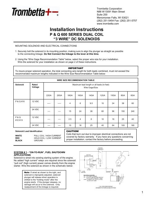
Installation Instructions<br />
P & Q 600 SERIES DUAL COIL<br />
“3 WIRE” <strong>DC</strong> SOLENOIDS<br />
MOUNTING SOLENOID AND ELECTRICAL CONNECTIONS<br />
<strong>Trombetta</strong> Corporation<br />
N88 W13091 Main Street<br />
Suite 200<br />
Menomonee Falls, WI 53021<br />
(262) 251-5454 Fax: (262) 251-5757<br />
www.trombetta.com<br />
1. Securely bolt the solenoid in its mounting position, making sure to align the plunger as straight as possible<br />
to the connecting linkage. Do Not Connect the linkage to the lever at this time.<br />
2. Using the Wire Gage Recommendation Table below, select the proper wire size for your installation.<br />
Wire the solenoid for your installation as shown on page 2 of these instructions.<br />
IMPORTANT<br />
To insure proper solenoid operation, the total connecting wire length for both leads combined, must not exceed the<br />
recommended maximum lengths indicated in the Wire Size Recommendation Table below:<br />
WIRE SIZE RECOMMENDATION TABLE<br />
Solenoid<br />
Rated<br />
Voltage<br />
Maximum lead length or all leads (in feet)<br />
Wire Gage/Size<br />
22GA<br />
20GA<br />
18GA<br />
16GA<br />
14GA<br />
12GA<br />
10GA<br />
8GA<br />
6GA<br />
P & Q 610<br />
12 V<strong>DC</strong><br />
-----<br />
-----<br />
4<br />
6<br />
9.5<br />
15<br />
24<br />
38<br />
60<br />
24 V<strong>DC</strong><br />
----<br />
----<br />
15<br />
24<br />
38<br />
60<br />
96<br />
150<br />
240<br />
P & Q<br />
612 613<br />
12 V<strong>DC</strong><br />
----<br />
----<br />
2.5<br />
4<br />
6<br />
10<br />
16<br />
25<br />
40<br />
24 V<strong>DC</strong><br />
----<br />
----<br />
10<br />
16<br />
25<br />
40<br />
64<br />
100<br />
160<br />
Solenoid Lead Identification:<br />
WHITE<br />
PULL COIL / HIGH CURRENT<br />
RED<br />
HOLD COIL / LOW CURRENT<br />
BLACK<br />
GROUND<br />
CAUTION!<br />
Coils that burn out due to improper electrical connections are not<br />
covered by factory warranty. If you have any questions concerning<br />
proper installation, contact the factory before proceeding.<br />
SYSTEM # 1 - “ON-TO-RUN”, FUEL SHUTDOWN<br />
APPLICATIONS<br />
Solenoid is wired into existing starting system of the engine.<br />
No added high current relays are required since the solenoid<br />
pull coil (high current) power comes directly from the engine<br />
starter. Wire the solenoid as shown in the schematic below:<br />
Note: If wired as shown to the right, and<br />
solenoid is improperly adjusted, solenoid<br />
plunger will release when operation is<br />
shifted to the holding mode after the<br />
engine starts. If the plunger releases, no<br />
damage will occur to the solenoid. Only<br />
readjustment of the linkage is required.<br />
1
SYSTEM # 2 - Engine speed/RPM control and many other applications<br />
On applications other than On-To-Run fuel shut down, a solenoid electronic control module is required to allow the solenoid to operate in<br />
a continuous duty mode without damaging the solenoid. Wire the solenoid and module as shown below. Do Not mount the module<br />
directly on the engine or other high vibration point. Keep module away from direct heat sources.<br />
WIRED DIRECT (S500-A5)<br />
WIRED FOR REMOTE OPERATION (S500-A6)<br />
24 Volt<br />
Installations<br />
Although the<br />
module is capable<br />
of 12 or 24 volt<br />
input, only the 12<br />
volt system can be<br />
wired with its<br />
output going<br />
directly to the<br />
solenoid as<br />
depicted in the<br />
diagrams above.<br />
The 24 volt output<br />
(pull-in) MUST be<br />
wired through an<br />
external contactor.<br />
Failure to do so will<br />
result in reduced<br />
module life.<br />
WIRED DIRECT (S500-A5)<br />
WIRED FOR REMOTE OPERATION (S500-A6)<br />
WIRED DIRECT (S500-A50)<br />
WIRED FOR REMOTE OPERATION (S500-A60)<br />
*** Note when using an S500-A50 or<br />
S500-A60 module all of the solenoid<br />
connections must connect to the<br />
module as shown. Do not connect any<br />
of the solenoid leads to another ground<br />
point in the system.<br />
* Note - some solenoids only have 2 wires.<br />
If this is the case, use the black and either<br />
the white or red wire connection points on<br />
the module<br />
3. S500-A5 & A50 Modules - After making the final wiring check, energize the solenoid hold coil by turning the switch to the on position and<br />
manually push the solenoid plunger to the seated position. The plunger should remain seated.<br />
S500-A6 & A60 Modules - After making the final wiring check, energize the solenoid hold coil by turning the switch to the on position, close<br />
the run switch on the module and manually push the solenoid plunger to the seated position. The plunger should remain seated.<br />
4. With solenoid seated, connect the linkage to the plunger , adjust the linkage for proper operation and tighten all connection points securely.<br />
5. De-energize the solenoid. Visually check the linkage by manually moving the linkage thought its entire stroke to make sure the linkage is<br />
free from obstructions. Total movement of the plunger MUST NOT exceed the recommended stroke of the solenoid.<br />
X190 (H10558) Revision 8/23/07 <strong>Trombetta</strong> Corporation<br />
2