ITG-3050 Product Specification Revision 1.3 - InvenSense
ITG-3050 Product Specification Revision 1.3 - InvenSense
ITG-3050 Product Specification Revision 1.3 - InvenSense

You also want an ePaper? Increase the reach of your titles
YUMPU automatically turns print PDFs into web optimized ePapers that Google loves.
<strong>ITG</strong>-<strong>3050</strong> <strong>Product</strong> <strong>Specification</strong><br />
Document Number: PS-<strong>ITG</strong>-<strong>3050</strong>-00<br />
<strong>Revision</strong>: <strong>1.3</strong><br />
Release Date: 08/25/2011<br />
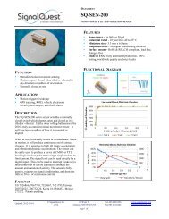
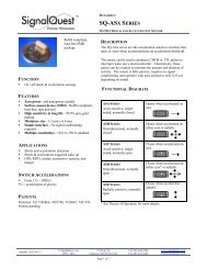
7.2.2 AUX_VDDIO = 1<br />
When AUX_VDDIO is set to 1 by the user, VLOGIC is the power supply voltage for the microprocessor<br />
system bus and VDD is the power supply for the accelerometer secondary bus, as shown in the figure below.<br />
This is useful when interfacing to a 3 rd -party accelerometer where there is only one supply for both the logic<br />
and analog sections of the 3 rd party accelerometer.<br />
VLOGIC<br />
(0V - VLOGIC)<br />
SYSTEM BUS<br />
System<br />
Processor<br />
VDD<br />
VDD<br />
VLOGIC<br />
SDA<br />
SCL<br />
INT<br />
(0V - VLOGIC)<br />
(0V - VLOGIC)<br />
(0V - VLOGIC)<br />
CLKIN<br />
FSYNC<br />
SDA<br />
SCL<br />
(0V - VLOGIC)<br />
(0V - VLOGIC)<br />
VDD<br />
VLOGIC<br />
VLOGIC<br />
<strong>ITG</strong>-<strong>3050</strong><br />
VDD<br />
(0V, VLOGIC)<br />
VLOGIC<br />
AD0<br />
CLKOUT<br />
AUX_DA<br />
AUX_CL<br />
0V - VDD<br />
0V - VDD<br />
0V - VDD<br />
DIO<br />
SDA<br />
SCL<br />
3 rd Party<br />
Accel<br />
INT 1<br />
INT 2<br />
ADDR<br />
0V - VDD<br />
(0V - VLOGIC)<br />
(0V - VLOGIC)<br />
Voltage/<br />
Configuration<br />
VLOGIC<br />
VDD<br />
Configuration 1 Configuration 2<br />
1.8V±5%<br />
2.5V±5%<br />
3.0V±5%<br />
3.0V±5%<br />
AUX_VDDIO 1 1<br />
Notes:<br />
1. AUX_VDDIO is bit 7 in Register 24, and determines the IO voltage levels of AUX_DA and<br />
AUX_CL (1 = set output levels relative to VDD)<br />
2. CLKOUT is always referenced to VDD<br />
3. Other <strong>ITG</strong>-<strong>3050</strong> logic IO are always referenced to VLOGIC<br />
4. Third-party accelerometer logic levels are referenced to VDD; setting INT1 and INT2 to opendrain<br />
configuration provides voltage compatibility when VDD ≠ VLOGIC.<br />
When VDD = VLOGIC, INT1 and INT2 may be set to push-pull outputs, and the external pull-up<br />
resistors will not be needed.<br />
I/O Levels and Connections for Two Example Power Configurations (AUX_VDDIO = 1)<br />
Note: Actual configuration will depend on the type of 3 rd -party accelerometer used.<br />
30 of 42