ITG-3050 Product Specification Revision 1.3 - InvenSense
ITG-3050 Product Specification Revision 1.3 - InvenSense
ITG-3050 Product Specification Revision 1.3 - InvenSense

You also want an ePaper? Increase the reach of your titles
YUMPU automatically turns print PDFs into web optimized ePapers that Google loves.
<strong>ITG</strong>-<strong>3050</strong> <strong>Product</strong> <strong>Specification</strong><br />
Document Number: PS-<strong>ITG</strong>-<strong>3050</strong>-00<br />
<strong>Revision</strong>: <strong>1.3</strong><br />
Release Date: 08/25/2011<br />
5.6 3 rd Party Accelerometer Configurations<br />
There are two options for connecting a 3 rd party accelerometer to the system comprised of the <strong>ITG</strong>-<strong>3050</strong> and<br />
the application processor.<br />
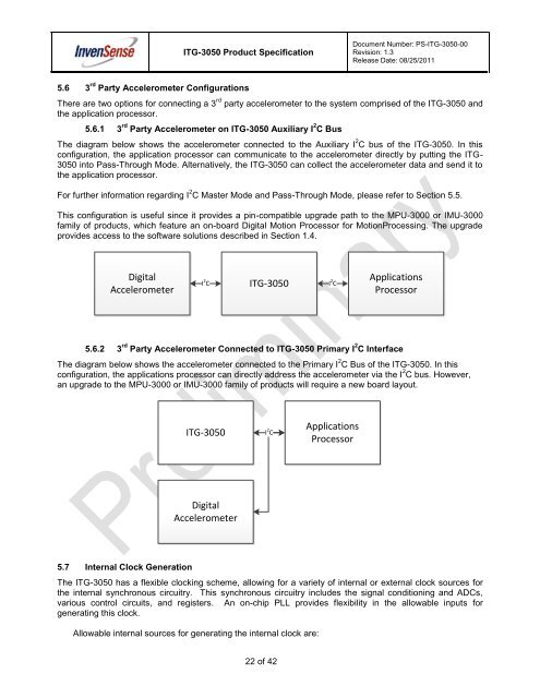
5.6.1 3 rd Party Accelerometer on <strong>ITG</strong>-<strong>3050</strong> Auxiliary I 2 C Bus<br />
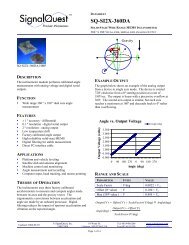
The diagram below shows the accelerometer connected to the Auxiliary I 2 C bus of the <strong>ITG</strong>-<strong>3050</strong>. In this<br />
configuration, the application processor can communicate to the accelerometer directly by putting the <strong>ITG</strong>-<br />
<strong>3050</strong> into Pass-Through Mode. Alternatively, the <strong>ITG</strong>-<strong>3050</strong> can collect the accelerometer data and send it to<br />
the application processor.<br />
For further information regarding I 2 C Master Mode and Pass-Through Mode, please refer to Section 5.5.<br />
This configuration is useful since it provides a pin-compatible upgrade path to the MPU-3000 or IMU-3000<br />
family of products, which feature an on-board Digital Motion Processor for MotionProcessing. The upgrade<br />
provides access to the software solutions described in Section 1.4.<br />
Digital<br />
Accelerometer<br />
I 2 C<br />
<strong>ITG</strong>-<strong>3050</strong><br />
I 2 C<br />
Applications<br />
Processor<br />
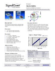
5.6.2 3 rd Party Accelerometer Connected to <strong>ITG</strong>-<strong>3050</strong> Primary I 2 C Interface<br />
The diagram below shows the accelerometer connected to the Primary I 2 C Bus of the <strong>ITG</strong>-<strong>3050</strong>. In this<br />
configuration, the applications processor can directly address the accelerometer via the I 2 C bus. However,<br />
an upgrade to the MPU-3000 or IMU-3000 family of products will require a new board layout.<br />
<strong>ITG</strong>-<strong>3050</strong><br />
I 2 C<br />
Applications<br />
Processor<br />
Digital<br />
Accelerometer<br />
5.7 Internal Clock Generation<br />
The <strong>ITG</strong>-<strong>3050</strong> has a flexible clocking scheme, allowing for a variety of internal or external clock sources for<br />
the internal synchronous circuitry. This synchronous circuitry includes the signal conditioning and ADCs,<br />
various control circuits, and registers. An on-chip PLL provides flexibility in the allowable inputs for<br />
generating this clock.<br />
Allowable internal sources for generating the internal clock are:<br />
22 of 42