Download LED Status Indicators White Paper (PDF) - Proflow Systems
Download LED Status Indicators White Paper (PDF) - Proflow Systems
Download LED Status Indicators White Paper (PDF) - Proflow Systems

Create successful ePaper yourself
Turn your PDF publications into a flip-book with our unique Google optimized e-Paper software.
<strong>LED</strong> <strong>Status</strong> <strong>Indicators</strong><br />
Use in Fuse Terminals and Modules<br />
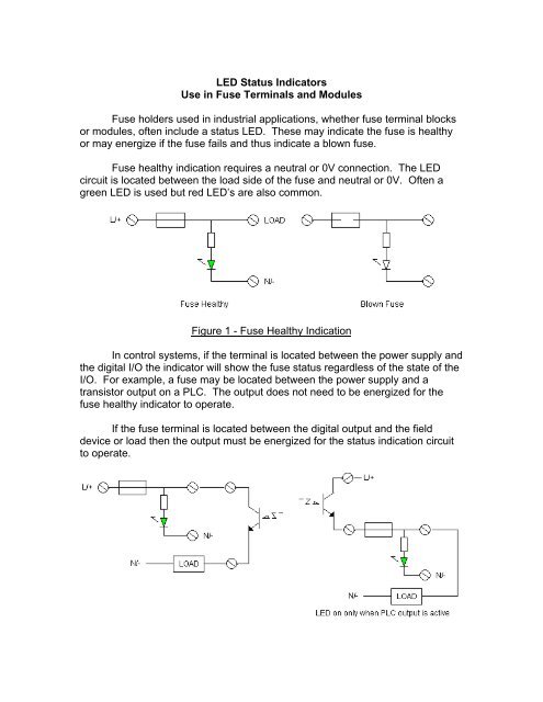
Fuse holders used in industrial applications, whether fuse terminal blocks<br />
or modules, often include a status <strong>LED</strong>. These may indicate the fuse is healthy<br />
or may energize if the fuse fails and thus indicate a blown fuse.<br />
Fuse healthy indication requires a neutral or 0V connection. The <strong>LED</strong><br />
circuit is located between the load side of the fuse and neutral or 0V. Often a<br />
green <strong>LED</strong> is used but red <strong>LED</strong>’s are also common.<br />
Figure 1 - Fuse Healthy Indication<br />
In control systems, if the terminal is located between the power supply and<br />
the digital I/O the indicator will show the fuse status regardless of the state of the<br />
I/O. For example, a fuse may be located between the power supply and a<br />
transistor output on a PLC. The output does not need to be energized for the<br />
fuse healthy indicator to operate.<br />
If the fuse terminal is located between the digital output and the field<br />
device or load then the output must be energized for the status indication circuit<br />
to operate.
Figure 2 - Connection to PLC Digital Output<br />
When the fuse fails the indicator turns off so there is no indicator current<br />
produced in a blown fuse situation. Fuse modules, i.e. a printed circuit board in a<br />
DIN rail mounted housing, can include the neutral / 0V connection so fuse<br />
healthy indication is easily achieved. However, most fuse terminals do not<br />
include terminations for the neutral / 0V so this type of status indication is less<br />
common than blown fuse indication.<br />
In the case of blown fuse indication, the <strong>LED</strong> circuit is located in parallel<br />
with the fuse. When the fuse is healthy the voltage drop across the indicator<br />
circuit is insufficient to energize the <strong>LED</strong>. If the fuse blows the supply voltage is<br />
now applied to the indicator circuit and the <strong>LED</strong> illuminates. As the impedance of<br />
the <strong>LED</strong> circuit is generally much higher than the load the majority of the supply<br />
voltage is applied to the <strong>LED</strong> circuit.<br />
Figure 3 - Blown Fuse Indication<br />
Figure 4 - Connection to PLC Digital Output
No terminations for the neutral / 0V are required. The drawback is the<br />
<strong>LED</strong> circuit produces a current flow through the load when the fuse is blown.<br />
This “leakage current” is undesirable and should be kept to a minimum so that it<br />
does not pose a safety hazard. <strong>LED</strong> currents as high as 2.5-3mA are not<br />
uncommon. At least one DIN rail fuse terminal supplier offers blown fuse<br />
indication that draws 0.25-0.5mA and still provides highly visible <strong>LED</strong>’s.<br />
Another drawback with blown fuse indication is that the indicator only<br />
functions when the PLC output is energized.<br />
Figure 5 - Leakage Current<br />
Emphatec’s new DEPRO - CLSI offers the best of both worlds - no<br />
leakage current fuse healthy indication with no need to provide a neutral / 0V<br />
connection. This is achieved by installing current sensing in series with the fuse.<br />
If the fuse is powered and healthy and the load is connected (and not open<br />
circuit) then the indicating <strong>LED</strong> energizes. Like blown fuse indication the<br />
indicator circuit only works when the PLC output is energized.<br />
Figure 6 - DEPRO - CLSI Fuse Healthy Indication<br />
The current sensing circuit must be compact (current transformers would<br />
be too large) and introduce minimal voltage drop. Emphatec’s circuit drops the<br />
voltage by approximately 0.8V regardless of the current flow so to keep power
dissipation to a minimum the maximum fuse rating is 500mA. This is more than<br />
sufficient for the majority of PLC I/O and control loop applications.<br />
The DEPRO - CLSI is designed for both AC and DC voltages and<br />
operates from 12V to 230V - one fuse module will work in a wide range of<br />
applications. The <strong>LED</strong> intensity is not dependant on the supply voltage but is<br />
optimal at a load current of 10mA of higher. At lower load currents it may be<br />
difficult to see the <strong>LED</strong> when illuminated.<br />
Key Features of the DEPRO - CLSI:<br />
- Wide operating voltage range: 12-230Vac/dc<br />
- Fuse healthy indication without the need for a neutral or 0V connection<br />
- No leakage current<br />
- Indicates control loop wiring is intact, fuse is healthy and load is drawing current<br />
- Requires just 11.2mm of DIN rail<br />
- Mounts on 32mm and 35mm DIN rails<br />
- Class 1 Division 2 certified for use in hazardous locations