IndraControl VPP 21.1 Project Planning Manual - Bosch Rexroth
IndraControl VPP 21.1 Project Planning Manual - Bosch Rexroth
IndraControl VPP 21.1 Project Planning Manual - Bosch Rexroth

You also want an ePaper? Increase the reach of your titles
YUMPU automatically turns print PDFs into web optimized ePapers that Google loves.
Electric Drives<br />
Linear Motion and<br />
and Controls Hydraulics<br />
Assembly Technologies Pneumatics Service<br />
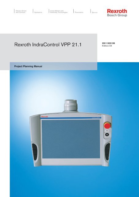
<strong>Rexroth</strong> <strong>IndraControl</strong> <strong>VPP</strong> <strong>21.1</strong><br />
R911305199<br />
Edition 03<br />
<strong>Project</strong> <strong>Planning</strong> <strong>Manual</strong>
<strong>Bosch</strong> <strong>Rexroth</strong> AG | Electric Drives<br />
and Controls<br />
<strong>Rexroth</strong> <strong>IndraControl</strong> <strong>VPP</strong> <strong>21.1</strong> | <strong>Project</strong> <strong>Planning</strong> <strong>Manual</strong><br />
Title<br />
Type of Documentation<br />
Document Typecode<br />
Internal File Reference<br />
Purpose of Documentation<br />
Record of Revision<br />
<strong>Rexroth</strong> <strong>IndraControl</strong> <strong>VPP</strong> <strong>21.1</strong><br />
<strong>Project</strong> <strong>Planning</strong> <strong>Manual</strong><br />
DOK-SUPPL*-<strong>VPP</strong>*<strong>21.1</strong>***-PR03-EN-P<br />
RS-32365cf1b60b88420a6846a0005af63d-1-en-US-5<br />
This documentation describes the operator terminal <strong>IndraControl</strong> <strong>VPP</strong> <strong>21.1</strong>.<br />
Edition Release Date Notes<br />
120-2100-B360-01/EN 01.2004 First edition<br />
120-2100-B360-02/EN 02.2005 Second edition<br />
120-2100-B360-03/EN 02.2008 Third edition<br />
Copyright<br />
Validity<br />
Published by<br />
Note<br />
© 2007 <strong>Bosch</strong> <strong>Rexroth</strong> AG<br />
Copying this document, giving it to others and the use or communication of the<br />
contents thereof without express authority, are forbidden. Offenders are liable<br />
for the payment of damages. All rights are reserved in the event of the grant of<br />
a patent or the registration of a utility model or design (DIN 34-1).<br />
The specified data is for product description purposes only and may not be<br />
deemed to be guaranteed unless expressly confirmed in the contract. All rights<br />
are reserved with respect to the content of this documentation and the availability<br />
of the product.<br />
<strong>Bosch</strong> <strong>Rexroth</strong> AG<br />
Bgm.-Dr.-Nebel-Str. 2 ■ 97816 Lohr am Main, Germany<br />
Phone +49 (0)93 52/ 40-0 ■ Fax +49 (0)93 52/ 40-48 85<br />
http://www.boschrexroth.com/<br />
Dep. BRC/EAY2 (MK/MePe)<br />
Dep. BRC/EAP1 (HP/MePe)<br />
This document has been printed on chlorine-free bleached paper.
<strong>Project</strong> <strong>Planning</strong> <strong>Manual</strong> | <strong>Rexroth</strong> <strong>IndraControl</strong> <strong>VPP</strong> <strong>21.1</strong> Electric Drives<br />
and Controls<br />
Table of Contents<br />
| <strong>Bosch</strong> <strong>Rexroth</strong> AG I/III<br />
Table of Contents<br />
1 System Representation.................................................................................................. 1<br />
1.1 Short Description.................................................................................................................................... 1<br />
1.2 Device Variants ...................................................................................................................................... 1<br />
1.2.1 Overview.............................................................................................................................................. 1<br />
1.2.2 Device Variant BQ............................................................................................................................... 1<br />
1.2.3 Device Variant BP............................................................................................................................... 2<br />
1.3 Operating system.................................................................................................................................... 3<br />
1.4 BIOS settings.......................................................................................................................................... 3<br />
1.5 Commissioning....................................................................................................................................... 3<br />
2 Important Instructions on Use ....................................................................................... 5<br />
2.1 Appropriate Use ..................................................................................................................................... 5<br />
2.1.1 Introduction.......................................................................................................................................... 5<br />
2.1.2 Areas of Use and Application.............................................................................................................. 5<br />
2.2 Inappropriate Use................................................................................................................................... 6<br />
Page<br />
3 Safety Instructions for Electric Drives and Controls....................................................... 7<br />
3.1 Safety Instructions - General Information............................................................................................... 7<br />
3.1.1 Using the Safety Instructions and Passing them on to Others............................................................ 7<br />
3.1.2 How to Employ the Safety Instructions................................................................................................ 7<br />
3.1.3 Explanation of Warning Symbols and Degrees of Hazard Seriousness.............................................. 8<br />
3.1.4 Hazards by Improper Use.................................................................................................................... 9<br />
3.2 Instructions with Regard to Specific Dangers....................................................................................... 10<br />
3.2.1 Protection Against Contact with Electrical Parts and Housings......................................................... 10<br />
3.2.2 Protection Against Electric Shock by Protective Extra-Low Voltage................................................. 11<br />
3.2.3 Protection Against Dangerous Movements....................................................................................... 11<br />
3.2.4 Protection Against Magnetic and Electromagnetic Fields During Operation and Mounting.............. 14<br />
3.2.5 Protection Against Contact with Hot Parts......................................................................................... 14<br />
3.2.6 Protection During Handling and Mounting......................................................................................... 14<br />
3.2.7 Battery Safety.................................................................................................................................... 15<br />
3.2.8 Protection Against Pressurized Systems........................................................................................... 15<br />
4 Technical Data............................................................................................................. 17<br />
4.1 Front Panel .......................................................................................................................................... 17<br />
4.2 Technical Data of the Total Device ...................................................................................................... 17<br />
4.3 PC......................................................................................................................................................... 17<br />
4.4 Ambient Conditions............................................................................................................................... 18<br />
4.5 Used standards..................................................................................................................................... 18<br />
4.6 Wear Parts............................................................................................................................................ 19<br />
4.7 Compatibility Test................................................................................................................................. 20<br />
5 Dimensions.................................................................................................................. 21<br />
5.1 Housing Dimensions ............................................................................................................................ 21
II/III<br />
<strong>Bosch</strong> <strong>Rexroth</strong> AG | Electric Drives<br />
and Controls<br />
<strong>Rexroth</strong> <strong>IndraControl</strong> <strong>VPP</strong> <strong>21.1</strong> | <strong>Project</strong> <strong>Planning</strong> <strong>Manual</strong><br />
Table of Contents<br />
Page<br />
5.1.1 Housing dimensions of the <strong>VPP</strong> 21 BQ............................................................................................. 21<br />
5.1.2 Housing dimensions of the <strong>VPP</strong> 21 BP............................................................................................. 21<br />
5.2 Installation............................................................................................................................................. 22<br />
5.2.1 Installation Notes............................................................................................................................... 22<br />
5.2.2 Installation......................................................................................................................................... 22<br />
6 Display and Operating Components............................................................................ 25<br />
6.1 Display.................................................................................................................................................. 25<br />
6.1.1 General Information........................................................................................................................... 25<br />
6.1.2 Backlight Switch-off........................................................................................................................... 25<br />
General Information........................................................................................................................ 25<br />
Activate backlight switch-off:.......................................................................................................... 25<br />
6.2 Operator Terminals with Keypad.......................................................................................................... 25<br />
6.2.1 Overview............................................................................................................................................ 25<br />
6.2.2 Navigation keys................................................................................................................................. 26<br />
6.2.3 Key Block "Machine".......................................................................................................................... 27<br />
6.2.4 Function Key Blocks.......................................................................................................................... 27<br />
6.2.5 Key Blocks "Operation"...................................................................................................................... 27<br />
6.2.6 Numeric block.................................................................................................................................... 28<br />
6.2.7 Block with Cursor and Special Keys.................................................................................................. 28<br />
6.2.8 Key Mouse......................................................................................................................................... 29<br />
6.2.9 Labeling the Front Panel................................................................................................................... 29<br />
6.2.10 Keyboard Controller........................................................................................................................... 30<br />
General Information........................................................................................................................ 30<br />
Transmission of the Key Codes...................................................................................................... 30<br />
START, STOP, E-STOP................................................................................................................. 34<br />
6.3 Operator terminal with Touch Screen................................................................................................... 35<br />
6.3.1 Overview............................................................................................................................................ 35<br />
6.3.2 Navigation keys................................................................................................................................. 36<br />
6.3.3 Key Block "Machine".......................................................................................................................... 36<br />
6.3.4 Touch Screen Controller.................................................................................................................... 37<br />
7 <strong>VPP</strong> 21-Box................................................................................................................. 39<br />
7.1 Connector panel................................................................................................................................... 39<br />
7.2 Operating Display and Error Display.................................................................................................... 40<br />
7.3 Interfaces.............................................................................................................................................. 41<br />
7.3.1 General Information........................................................................................................................... 41<br />
7.3.2 Overview............................................................................................................................................ 41<br />
7.3.3 Serial Interface COM1 ...................................................................................................................... 41<br />
7.3.4 Settings of the Serial Interface.......................................................................................................... 42<br />
7.3.5 USB interface.................................................................................................................................... 42<br />
7.3.6 Ethernet Interfaces............................................................................................................................ 43<br />
7.3.7 PROFIBUS DP (optional).................................................................................................................. 44<br />
7.3.8 CAN (optional)................................................................................................................................... 44<br />
7.3.9 VGA Interface.................................................................................................................................... 45
<strong>Project</strong> <strong>Planning</strong> <strong>Manual</strong> | <strong>Rexroth</strong> <strong>IndraControl</strong> <strong>VPP</strong> <strong>21.1</strong> Electric Drives<br />
and Controls<br />
| <strong>Bosch</strong> <strong>Rexroth</strong> AG III/III<br />
Table of Contents<br />
Page<br />
7.3.10 Combined Keyboard/Mouse Interface............................................................................................... 46<br />
7.3.11 Mouse Interface................................................................................................................................. 47<br />
7.3.12 Power Supply, Digital outputs, Ready contact................................................................................... 47<br />
Overview......................................................................................................................................... 47<br />
Pin 1 and Pin 2: 24 VDC Supply..................................................................................................... 48<br />
Pin 3 and Pin 4: Fan Supply........................................................................................................... 50<br />
Pin 5 and Pin 6: Digital Outputs 1 and 2......................................................................................... 51<br />
Pin 7 and Pin 8: Ready contact...................................................................................................... 51<br />
7.3.13 Hard Disk........................................................................................................................................... 51<br />
7.3.14 Compact Flash Card.......................................................................................................................... 52<br />
8 Maintenance and Installation....................................................................................... 53<br />
8.1 General................................................................................................................................................. 53<br />
8.2 Hard Disc.............................................................................................................................................. 53<br />
8.3 Display.................................................................................................................................................. 54<br />
8.4 Buffer Battery........................................................................................................................................ 54<br />
8.5 Extension cards.................................................................................................................................... 55<br />
8.5.1 General Notes................................................................................................................................... 55<br />
8.5.2 PCI Card Installation.......................................................................................................................... 56<br />
9 Disposal and Environmental Protection....................................................................... 59<br />
9.1 Disposal................................................................................................................................................ 59<br />
9.1.1 Products............................................................................................................................................ 59<br />
9.1.2 Packaging Materials.......................................................................................................................... 59<br />
9.2 Environmental Protection...................................................................................................................... 59<br />
9.2.1 No Release of Hazardous Substances.............................................................................................. 59<br />
9.2.2 Materials Contained in the Products.................................................................................................. 59<br />
Electronic Devices.......................................................................................................................... 59<br />
Motors............................................................................................................................................. 59<br />
9.2.3 Recycling........................................................................................................................................... 60<br />
10 Ordering Information.................................................................................................... 61<br />
10.1 Type Code............................................................................................................................................ 61<br />
10.2 Accessories.......................................................................................................................................... 61<br />
11 Service and Support.................................................................................................... 63<br />
11.1 Helpdesk............................................................................................................................................... 63<br />
11.2 Service Hotline...................................................................................................................................... 63<br />
11.3 Internet.................................................................................................................................................. 63<br />
11.4 Helpful Information................................................................................................................................ 63<br />
Index............................................................................................................................ 65
<strong>Bosch</strong> <strong>Rexroth</strong> AG | Electric Drives<br />
and Controls<br />
<strong>Rexroth</strong> <strong>IndraControl</strong> <strong>VPP</strong> <strong>21.1</strong> | <strong>Project</strong> <strong>Planning</strong> <strong>Manual</strong>
<strong>Project</strong> <strong>Planning</strong> <strong>Manual</strong> | <strong>Rexroth</strong> <strong>IndraControl</strong> <strong>VPP</strong> <strong>21.1</strong> Electric Drives<br />
and Controls<br />
| <strong>Bosch</strong> <strong>Rexroth</strong> AG 1/65<br />
System Representation<br />
1 System Representation<br />
1.1 Short Description<br />
1.2 Device Variants<br />
1.2.1 Overview<br />
1.2.2 Device Variant BQ<br />
The hand-held terminal <strong>VPP</strong> <strong>21.1</strong> is a computer-based machine operator terminal<br />
consisting of<br />
●<br />
●<br />
●<br />
●<br />
an enclosed plastic housing (degree of protection, total device: IP 40, degree<br />
of protection, front panel: IP 64)<br />
a TFT display with and without touch screen,<br />
depending on the variant, different display and operating components and<br />
an integrated efficient industrial PC.<br />
<strong>VPP</strong> 21-type operator terminals are provided for bracket mounting. Because of<br />
its design they are predestinated as "operator panel control". For this, special<br />
buttons (control ON, control OFF, E-STOP) are mounted in the housing. On the<br />
left and right three navigation keys are integrated. To communicate with external<br />
components standardized field bus systems are used.<br />
The restricted extensible computer unit with power supply unit and field bus<br />
connection is located in the so-called <strong>VPP</strong> 21 box installed in the plastic housing<br />
of the <strong>VPP</strong> 21.<br />
The The hand-held terminal <strong>VPP</strong> 21 are available as device variant BQ (with<br />
keypad) or as device variant BP ( with touch screen).<br />
This variant provides – below the 14" TFT display - for a keypad with function<br />
keys, a numeric block, cursor keys and further keys to be labeled by slide-in<br />
strips.
2/65 <strong>Bosch</strong> <strong>Rexroth</strong> AG | Electric Drives<br />
and Controls<br />
<strong>Rexroth</strong> <strong>IndraControl</strong> <strong>VPP</strong> <strong>21.1</strong> | <strong>Project</strong> <strong>Planning</strong> <strong>Manual</strong><br />
System Representation<br />
Fig.1-1:<br />
1.2.3 Device Variant BP<br />
Front panel – device variant BQ<br />
In contrast, the <strong>VPP</strong> <strong>21.1</strong> BP has no keypad, but a touch screen.<br />
The front panel with touch screen allows to operate the application software via<br />
the touch-sensitive surface of the display without keyboard and mouse.
<strong>Project</strong> <strong>Planning</strong> <strong>Manual</strong> | <strong>Rexroth</strong> <strong>IndraControl</strong> <strong>VPP</strong> <strong>21.1</strong> Electric Drives<br />
and Controls<br />
| <strong>Bosch</strong> <strong>Rexroth</strong> AG 3/65<br />
System Representation<br />
Fig.1-2:<br />
Front panel – device variant BP<br />
1.3 Operating system<br />
1.4 BIOS settings<br />
1.5 Commissioning<br />
For license reasons the hand-held terminals <strong>VPP</strong> 21 are only delivered with<br />
already installed operating system. At present, Windows XP is used.<br />
The delivered operating systems may only be used in the industrial environment.<br />
Use in the office area, e. g. on a secretary's computer, is not allowed.<br />
When leaving the factory, the BIOS settings have been made according to the<br />
respective device variant.<br />
Mount the device properly (for this, see chapter chapter 5.2 "Installation" on<br />
page 22). Then, connect the device to the power supply ( 24 V) and, if required,<br />
to the network.
<strong>Bosch</strong> <strong>Rexroth</strong> AG | Electric Drives<br />
and Controls<br />
<strong>Rexroth</strong> <strong>IndraControl</strong> <strong>VPP</strong> <strong>21.1</strong> | <strong>Project</strong> <strong>Planning</strong> <strong>Manual</strong>
<strong>Project</strong> <strong>Planning</strong> <strong>Manual</strong> | <strong>Rexroth</strong> <strong>IndraControl</strong> <strong>VPP</strong> <strong>21.1</strong> Electric Drives<br />
and Controls<br />
| <strong>Bosch</strong> <strong>Rexroth</strong> AG 5/65<br />
Important Instructions on Use<br />
2 Important Instructions on Use<br />
2.1 Appropriate Use<br />
2.1.1 Introduction<br />
<strong>Rexroth</strong> products represent state-of-the-art developments and manufacturing.<br />
They are tested prior to delivery to ensure operating safety and reliability.<br />
WARNING<br />
Physical and property damage due to the inappropriate use of products!<br />
The products are designed for their use within the industrial environment and<br />
may therefore only be used for the intended purpose. If the use is inappropriate,<br />
situations causing physical damage as well as property damage can occur.<br />
2.1.2 Areas of Use and Application<br />
<strong>Rexroth</strong> disclaims as manufacturer any warranty, liability or for<br />
damages occurring due to inappropriate use of the products. Furthermore,<br />
<strong>Rexroth</strong> is not paying any compensation. The user is<br />
responsible for any risks resulting from the products not being used<br />
as intended.<br />
Before using <strong>Rexroth</strong> products, the following pre-requisites must be fulfilled to<br />
ensure an appropriate use of the products:<br />
●<br />
●<br />
●<br />
●<br />
Anyone handling one of the <strong>Rexroth</strong> products in any way has to read and<br />
understand the respective safety instructions as well as the instructions<br />
on the appropriate use.<br />
Hardware products have to remain in their original state, in other words,<br />
no modification regarding the design are allowed. Software products may<br />
not be decompiled and their source codes may not be modified.<br />
Damaged or faulty products are not to be implemented or put into operation.<br />
It is to be ensured that the corresponding products are installed according<br />
to the specifications of the documentation.<br />
hand-held terminal <strong>VPP</strong> <strong>21.1</strong> of <strong>Rexroth</strong> are machine operating fields developed<br />
for control tasks. Typical areas of application of the hand-held terminal<br />
<strong>VPP</strong> <strong>21.1</strong> are:<br />
●<br />
●<br />
●<br />
Lathes<br />
Milling machines<br />
Processing machine<br />
It can be necessary to connect additional sensors and actuators to control and<br />
monitor the hand-held terminal <strong>VPP</strong> <strong>21.1</strong>.<br />
The hand-held terminal <strong>VPP</strong> <strong>21.1</strong>may only be used with the accessories<br />
and add-on components specified in this documentation.<br />
Components that are not named explicitly may neither be mounted<br />
nor connected. Same is applicable for cables and wires.<br />
Operation my only be carried out in the configurations and combinations<br />
of the components specified and with the software and<br />
firmware determined in the respective functional description.<br />
Each drive control device has to be programmed before commissioning so that<br />
the motor carries out the specific functions for the application.
6/65 <strong>Bosch</strong> <strong>Rexroth</strong> AG | Electric Drives<br />
and Controls<br />
<strong>Rexroth</strong> <strong>IndraControl</strong> <strong>VPP</strong> <strong>21.1</strong> | <strong>Project</strong> <strong>Planning</strong> <strong>Manual</strong><br />
Important Instructions on Use<br />
2.2 Inappropriate Use<br />
The hand-held terminal <strong>VPP</strong> <strong>21.1</strong> were developed for the single axis as well as<br />
for the multiple axes drive tasks and control tasks.<br />
For the application-specific use of the hand-held terminal <strong>VPP</strong> <strong>21.1</strong>, device<br />
types with a different drive performance and different interfaces are available.<br />
For the application-specific use of the machine operating terminals and visualization<br />
terminals , device types with a different equipment and different interfaces<br />
are available.<br />
Typical areas of application of the hand-held terminal <strong>VPP</strong> <strong>21.1</strong> are:<br />
●<br />
●<br />
●<br />
●<br />
[Handling systems and assembly systems]<br />
[Packaging and processing machines]<br />
[Printing machines and paper processing machines]<br />
[Machine tools]<br />
hand-held terminal The <strong>VPP</strong> <strong>21.1</strong> may only be operated under the assembly<br />
conditions and installation conditions, in the specified position of application<br />
and under the specified ambient conditions (temperature, degree of protection,<br />
humidity, EMC etc.) given in this documentation.<br />
The application of hand-held terminal that are <strong>VPP</strong> <strong>21.1</strong> not within the specified<br />
areas of application or under operating conditions deviating from the operating<br />
conditions and technical data specified in the documentation is considered as<br />
"inappropriate".<br />
hand-held terminal <strong>VPP</strong> <strong>21.1</strong> may not be used if ...<br />
●<br />
●<br />
they are exposed to operating conditions that do not fulfill the ambient<br />
conditions specified. Operation under water, under extreme temperature<br />
fluctuations or extreme maximum temperatures is not allowed for example:.<br />
the <strong>Rexroth</strong> applications that are not released explicitly. Please note the<br />
general statements in the general safety instructions!
<strong>Project</strong> <strong>Planning</strong> <strong>Manual</strong> | <strong>Rexroth</strong> <strong>IndraControl</strong> <strong>VPP</strong> <strong>21.1</strong> Electric Drives<br />
and Controls<br />
| <strong>Bosch</strong> <strong>Rexroth</strong> AG 7/65<br />
Safety Instructions for Electric Drives and Controls<br />
3 Safety Instructions for Electric Drives and Controls<br />
3.1 Safety Instructions - General Information<br />
3.1.1 Using the Safety Instructions and Passing them on to Others<br />
Do not attempt to install or commission this device without first reading all documentation<br />
provided with the product. Read and understand these safety<br />
instructions and all user documentation prior to working with the device. If you<br />
do not have the user documentation for the device, contact your responsible<br />
<strong>Bosch</strong> <strong>Rexroth</strong> sales representative. Ask for these documents to be sent immediately<br />
to the person or persons responsible for the safe operation of the<br />
device.<br />
If the device is resold, rented and/or passed on to others in any other form,<br />
these safety instructions must be delivered with the device in the official language<br />
of the user's country.<br />
WARNING<br />
Improper use of these devices, failure to follow the safety instructions in<br />
this document or tampering with the product, including disabling of safety<br />
devices, may result in material damage, bodily harm, electric shock<br />
or even death!<br />
Observe the safety instructions!<br />
3.1.2 How to Employ the Safety Instructions<br />
Read these instructions before initial commissioning of the equipment in order<br />
to eliminate the risk of bodily harm and/or material damage. Follow these safety<br />
instructions at all times.<br />
●<br />
●<br />
●<br />
●<br />
●<br />
<strong>Bosch</strong> <strong>Rexroth</strong> AG is not liable for damages resulting from failure to observe<br />
the warnings provided in this documentation.<br />
Read the operating, maintenance and safety instructions in your language<br />
before commissioning the machine. If you find that you cannot completely<br />
understand the documentation for your product, please ask your supplier<br />
to clarify.<br />
Proper and correct transport, storage, assembly and installation, as well<br />
as care in operation and maintenance, are prerequisites for optimal and<br />
safe operation of this device.<br />
Only assign trained and qualified persons to work with electrical installations:<br />
– Only persons who are trained and qualified for the use and operation<br />
of the device may work on this device or within its proximity. The<br />
persons are qualified if they have sufficient knowledge of the assembly,<br />
installation and operation of the product, as well as an understanding<br />
of all warnings and precautionary measures noted in these<br />
instructions.<br />
– Furthermore, they must be trained, instructed and qualified to switch<br />
electrical circuits and devices on and off in accordance with technical<br />
safety regulations, to ground them and to mark them according to the<br />
requirements of safe work practices. They must have adequate safety<br />
equipment and be trained in first aid.<br />
Only use spare parts and accessories approved by the manufacturer.
8/65 <strong>Bosch</strong> <strong>Rexroth</strong> AG | Electric Drives<br />
and Controls<br />
<strong>Rexroth</strong> <strong>IndraControl</strong> <strong>VPP</strong> <strong>21.1</strong> | <strong>Project</strong> <strong>Planning</strong> <strong>Manual</strong><br />
Safety Instructions for Electric Drives and Controls<br />
●<br />
●<br />
●<br />
●<br />
●<br />
●<br />
●<br />
●<br />
●<br />
Follow all safety regulations and requirements for the specific application<br />
as practiced in the country of use.<br />
The devices have been designed for installation in industrial machinery.<br />
The ambient conditions given in the product documentation must be observed.<br />
Only use safety-relevant applications that are clearly and explicitly approved<br />
in the <strong>Project</strong> <strong>Planning</strong> <strong>Manual</strong>. If this is not the case, they are<br />
excluded. Safety-relevant are all such applications which can cause danger<br />
to persons and material damage.<br />
The information given in the documentation of the product with regard to<br />
the use of the delivered components contains only examples of applications<br />
and suggestions.<br />
The machine and installation manufacturer must<br />
– make sure that the delivered components are suited for his individual<br />
application and check the information given in this documentation<br />
with regard to the use of the components,<br />
– make sure that his application complies with the applicable safety<br />
regulations and standards and carry out the required measures,<br />
modifications and complements.<br />
Commissioning of the delivered components is only permitted once it is<br />
sure that the machine or installation in which they are installed complies<br />
with the national regulations, safety specifications and standards of the<br />
application.<br />
Operation is only permitted if the national EMC regulations for the application<br />
are met.<br />
The instructions for installation in accordance with EMC requirements can<br />
be found in the section on EMC in the respective documentation (<strong>Project</strong><br />
<strong>Planning</strong> <strong>Manual</strong>s of components and system).<br />
The machine or installation manufacturer is responsible for compliance<br />
with the limiting values as prescribed in the national regulations.<br />
Technical data, connection and installation conditions are specified in the<br />
product documentation and must be followed at all times.<br />
National regulations which the user must take into account<br />
●<br />
●<br />
●<br />
●<br />
European countries: according to European EN standards<br />
United States of America (USA):<br />
– National Electrical Code (NEC)<br />
– National Electrical Manufacturers Association (NEMA), as well as<br />
local engineering regulations<br />
– regulations of the National Fire Protection Association (NFPA)<br />
Canada: Canadian Standards Association (CSA)<br />
Other countries:<br />
– International Organization for Standardization (ISO)<br />
– International Electrotechnical Commission (IEC)<br />
3.1.3 Explanation of Warning Symbols and Degrees of Hazard Seriousness<br />
The safety instructions describe the following degrees of hazard seriousness.<br />
The degree of hazard seriousness informs about the consequences resulting<br />
from non-compliance with the safety instructions:
<strong>Project</strong> <strong>Planning</strong> <strong>Manual</strong> | <strong>Rexroth</strong> <strong>IndraControl</strong> <strong>VPP</strong> <strong>21.1</strong> Electric Drives<br />
and Controls<br />
| <strong>Bosch</strong> <strong>Rexroth</strong> AG 9/65<br />
Safety Instructions for Electric Drives and Controls<br />
Warning symbol<br />
Signal word<br />
Danger<br />
Degree of hazard seriousness<br />
acc. to ANSI Z<br />
535.4-2002<br />
Death or severe bodily harm<br />
will occur.<br />
Warning<br />
Caution<br />
Death or severe bodily harm<br />
may occur.<br />
Minor or moderate bodily<br />
harm or material damage<br />
may occur.<br />
Fig.3-1: Hazard classification (according to ANSI Z 535)<br />
3.1.4 Hazards by Improper Use<br />
DANGER<br />
High electric voltage and high working current! Risk of death or severe<br />
bodily injury by electric shock!<br />
Observe the safety instructions!<br />
DANGER<br />
Dangerous movements! Danger to life, severe bodily harm or material<br />
damage by unintentional motor movements!<br />
Observe the safety instructions!<br />
WARNING<br />
High electric voltage because of incorrect connection! Risk of death or<br />
bodily injury by electric shock!<br />
Observe the safety instructions!<br />
WARNING<br />
Health hazard for persons with heart pacemakers, metal implants and<br />
hearing aids in proximity to electrical equipment!<br />
Observe the safety instructions!<br />
Hot surfaces on device housing! Danger of injury! Danger of burns!<br />
Observe the safety instructions!<br />
CAUTION<br />
CAUTION<br />
Risk of injury by improper handling! Risk of bodily injury by bruising,<br />
shearing, cutting, hitting or improper handling of pressurized lines!<br />
Observe the safety instructions!
10/65 <strong>Bosch</strong> <strong>Rexroth</strong> AG | Electric Drives<br />
and Controls<br />
<strong>Rexroth</strong> <strong>IndraControl</strong> <strong>VPP</strong> <strong>21.1</strong> | <strong>Project</strong> <strong>Planning</strong> <strong>Manual</strong><br />
Safety Instructions for Electric Drives and Controls<br />
CAUTION<br />
Risk of injury by improper handling of batteries!<br />
Observe the safety instructions!<br />
3.2 Instructions with Regard to Specific Dangers<br />
3.2.1 Protection Against Contact with Electrical Parts and Housings<br />
This section concerns devices and drive components with voltages<br />
of more than 50 Volt.<br />
Contact with parts conducting voltages above 50 Volts can cause personal<br />
danger and electric shock. When operating electrical equipment, it is unavoidable<br />
that some parts of the devices conduct dangerous voltage.<br />
DANGER<br />
High electrical voltage! Danger to life, electric shock and severe bodily<br />
injury!<br />
●<br />
●<br />
●<br />
●<br />
●<br />
●<br />
●<br />
●<br />
●<br />
●<br />
Only those trained and qualified to work with or on electrical equipment<br />
are permitted to operate, maintain and repair this equipment.<br />
Follow general construction and safety regulations when working on power<br />
installations.<br />
Before switching on the device, the equipment grounding conductor must<br />
have been non-detachably connected to all electrical equipment in accordance<br />
with the connection diagram.<br />
Do not operate electrical equipment at any time, even for brief measurements<br />
or tests, if the equipment grounding conductor is not permanently<br />
connected to the mounting points of the components provided for this<br />
purpose.<br />
Before working with electrical parts with voltage potentials higher than<br />
50 V, the device must be disconnected from the mains voltage or power<br />
supply unit. Provide a safeguard to prevent reconnection.<br />
With electrical drive and filter components, observe the following:<br />
Wait 30 minutes after switching off power to allow capacitors to discharge<br />
before beginning to work. Measure the electric voltage on the capacitors<br />
before beginning to work to make sure that the equipment is safe to touch.<br />
Never touch the electrical connection points of a component while power<br />
is turned on. Do not remove or plug in connectors when the component<br />
has been powered.<br />
Install the covers and guards provided with the equipment properly before<br />
switching the device on. Before switching the equipment on, cover and<br />
safeguard live parts safely to prevent contact with those parts.<br />
A residual-current-operated circuit-breaker or r.c.d. cannot be used for<br />
electric drives! Indirect contact must be prevented by other means, for<br />
example, by an overcurrent protective device according to the relevant<br />
standards.<br />
Secure built-in devices from direct touching of electrical parts by providing<br />
an external housing, for example a control cabinet.
<strong>Project</strong> <strong>Planning</strong> <strong>Manual</strong> | <strong>Rexroth</strong> <strong>IndraControl</strong> <strong>VPP</strong> <strong>21.1</strong> Electric Drives<br />
and Controls<br />
| <strong>Bosch</strong> <strong>Rexroth</strong> AG 11/65<br />
Safety Instructions for Electric Drives and Controls<br />
For electrical drive and filter components with voltages of more than<br />
50 volts, observe the following additional safety instructions.<br />
DANGER<br />
High housing voltage and high leakage current! Risk of death or bodily<br />
injury by electric shock!<br />
●<br />
●<br />
●<br />
●<br />
Before switching on, the housings of all electrical equipment and motors<br />
must be connected or grounded with the equipment grounding conductor<br />
to the grounding points. This is also applicable before short tests.<br />
The equipment grounding conductor of the electrical equipment and the<br />
devices must be non-detachably and permanently connected to the power<br />
supply unit at all times. The leakage current is greater than 3.5 mA.<br />
Over the total length, use copper wire of a cross section of a minimum of<br />
10 mm 2 for this equipment grounding connection!<br />
Before commissioning, also in trial runs, always attach the equipment<br />
grounding conductor or connect to the ground wire. Otherwise, high voltages<br />
may occur at the housing causing electric shock.<br />
3.2.2 Protection Against Electric Shock by Protective Extra-Low Voltage<br />
Protective extra-low voltage is used to allow connecting devices with basic insulation<br />
to extra-low voltage circuits.<br />
All connections and terminals with voltages between 5 and 50 volts at <strong>Rexroth</strong><br />
products are PELV systems. 1) It is therefore allowed to connect devices<br />
equipped with basic insulation (such as programming devices, PCs, notebooks,<br />
display units) to these connections and terminals.<br />
WARNING<br />
High electric voltage by incorrect connection! Risk of death or bodily<br />
injury by electric shock!<br />
If extra-low voltage circuits of devices containing voltages and circuits of more<br />
than 50 volts (e.g. the mains connection) are connected to <strong>Rexroth</strong> products,<br />
the connected extra-low voltage circuits must comply with the requirements for<br />
PELV. 2)<br />
3.2.3 Protection Against Dangerous Movements<br />
Dangerous movements can be caused by faulty control of connected motors.<br />
Some common examples are:<br />
●<br />
●<br />
●<br />
●<br />
●<br />
●<br />
improper or wrong wiring of cable connections<br />
incorrect operation of the equipment components<br />
wrong input of parameters before operation<br />
malfunction of sensors, encoders and monitoring devices<br />
defective components<br />
software or firmware errors<br />
Dangerous movements can occur immediately after equipment is switched on<br />
or even after an unspecified time of trouble-free operation.<br />
1) "Protective Extra-Low Voltage"<br />
2) "Protective Extra-Low Voltage"
12/65 <strong>Bosch</strong> <strong>Rexroth</strong> AG | Electric Drives<br />
and Controls<br />
<strong>Rexroth</strong> <strong>IndraControl</strong> <strong>VPP</strong> <strong>21.1</strong> | <strong>Project</strong> <strong>Planning</strong> <strong>Manual</strong><br />
Safety Instructions for Electric Drives and Controls<br />
The monitoring in the drive components will normally be sufficient to avoid faulty<br />
operation in the connected drives. Regarding personal safety, especially the<br />
danger of bodily harm and material damage, this alone cannot be relied upon<br />
to ensure complete safety. Until the integrated monitoring functions become<br />
effective, it must be assumed in any case that faulty drive movements will occur.<br />
The extent of faulty drive movements depends upon the type of control and the<br />
state of operation.
<strong>Project</strong> <strong>Planning</strong> <strong>Manual</strong> | <strong>Rexroth</strong> <strong>IndraControl</strong> <strong>VPP</strong> <strong>21.1</strong> Electric Drives<br />
and Controls<br />
| <strong>Bosch</strong> <strong>Rexroth</strong> AG 13/65<br />
Safety Instructions for Electric Drives and Controls<br />
DANGER<br />
Dangerous movements! Danger to life, risk of injury, severe bodily harm<br />
or material damage!<br />
●<br />
Ensure personal safety by means of qualified and tested higher-level<br />
monitoring devices or measures integrated in the installation.<br />
These measures have to be provided for by the user according to the<br />
specific conditions within the installation and a hazard and fault analysis.<br />
The safety regulations applicable for the installation have to be taken into<br />
consideration. Unintended machine motion or other malfunction is possible<br />
if safety devices are disabled, bypassed or not activated.<br />
To avoid accidents, bodily harm and/or material damage:<br />
●<br />
●<br />
●<br />
●<br />
●<br />
●<br />
●<br />
●<br />
●<br />
Keep free and clear of the machine’s range of motion and moving parts.<br />
Possible measures to prevent people from accidentally entering the<br />
machine’s range of motion:<br />
– use safety fences<br />
– use safety guards<br />
– use protective coverings<br />
– install light curtains or light barriers<br />
Fences and coverings must be strong enough to resist maximum possible<br />
momentum.<br />
Mount the emergency stop switch in the immediate reach of the operator.<br />
Verify that the emergency stop works before startup. Don’t operate the<br />
device if the emergency stop is not working.<br />
Isolate the drive power connection by means of an emergency stop circuit<br />
or use a safety related starting lockout to prevent unintentional start.<br />
Make sure that the drives are brought to a safe standstill before accessing<br />
or entering the danger zone.<br />
Additionally secure vertical axes against falling or dropping after switching<br />
off the motor power by, for example:<br />
– mechanically securing the vertical axes,<br />
– adding an external braking/ arrester/ clamping mechanism or<br />
– ensuring sufficient equilibration of the vertical axes.<br />
The standard equipment motor brake or an external brake controlled directly<br />
by the drive controller are not sufficient to guarantee personal<br />
safety!<br />
Disconnect electrical power to the equipment using a master switch and<br />
secure the switch against reconnection for:<br />
– maintenance and repair work<br />
– cleaning of equipment<br />
– long periods of discontinued equipment use<br />
Prevent the operation of high-frequency, remote control and radio equipment<br />
near electronics circuits and supply leads. If the use of such devices<br />
cannot be avoided, verify the system and the installation for possible malfunctions<br />
in all possible positions of normal use before initial startup. If<br />
necessary, perform a special electromagnetic compatibility (EMC) test on<br />
the installation.
14/65 <strong>Bosch</strong> <strong>Rexroth</strong> AG | Electric Drives<br />
and Controls<br />
<strong>Rexroth</strong> <strong>IndraControl</strong> <strong>VPP</strong> <strong>21.1</strong> | <strong>Project</strong> <strong>Planning</strong> <strong>Manual</strong><br />
Safety Instructions for Electric Drives and Controls<br />
3.2.4 Protection Against Magnetic and Electromagnetic Fields During Operation<br />
and Mounting<br />
Magnetic and electromagnetic fields generated by current-carrying conductors<br />
and permanent magnets in motors represent a serious personal danger to<br />
those with heart pacemakers, metal implants and hearing aids.<br />
WARNING<br />
Health hazard for persons with heart pacemakers, metal implants and<br />
hearing aids in proximity to electrical equipment!<br />
●<br />
●<br />
●<br />
Persons with heart pacemakers and metal implants are not permitted to<br />
enter following areas:<br />
– Areas in which electrical equipment and parts are mounted, being<br />
operated or commissioned.<br />
– Areas in which parts of motors with permanent magnets are being<br />
stored, repaired or mounted.<br />
If it is necessary for somebody with a pacemaker to enter such an area,<br />
a doctor must be consulted prior to doing so. The noise immunity of present<br />
or future implanted heart pacemakers differs greatly so that no general<br />
rules can be given.<br />
Those with metal implants or metal pieces, as well as with hearing aids,<br />
must consult a doctor before they enter the areas described above. Otherwise<br />
health hazards may occur.<br />
3.2.5 Protection Against Contact with Hot Parts<br />
CAUTION<br />
Hot surfaces at motor housings, on drive controllers or chokes! Danger<br />
of injury! Danger of burns!<br />
●<br />
●<br />
●<br />
●<br />
●<br />
●<br />
●<br />
Do not touch surfaces of device housings and chokes in the proximity of<br />
heat sources! Danger of burns!<br />
Do not touch housing surfaces of motors! Danger of burns!<br />
According to the operating conditions, temperatures can be higher than<br />
60 °C, 140°F during or after operation.<br />
Before accessing motors after having switched them off, let them cool<br />
down for a sufficiently long time. Cooling down can require up to 140 minutes!<br />
Roughly estimated, the time required for cooling down is five times<br />
the thermal time constant specified in the Technical Data.<br />
After switching drive controllers or chokes off, wait 15 minutes to allow<br />
them to cool down before touching them.<br />
Wear safety gloves or do not work at hot surfaces.<br />
For certain applications, the manufacturer of the end product, machine or<br />
installation, according to the respective safety regulations, has to take<br />
measures to avoid injuries caused by burns in the end application. These<br />
measures can be, for example: warnings, guards (shielding or barrier),<br />
technical documentation.<br />
3.2.6 Protection During Handling and Mounting<br />
In unfavorable conditions, handling and mounting certain parts and components<br />
in an improper way can cause injuries.
<strong>Project</strong> <strong>Planning</strong> <strong>Manual</strong> | <strong>Rexroth</strong> <strong>IndraControl</strong> <strong>VPP</strong> <strong>21.1</strong> Electric Drives<br />
and Controls<br />
| <strong>Bosch</strong> <strong>Rexroth</strong> AG 15/65<br />
Safety Instructions for Electric Drives and Controls<br />
CAUTION<br />
Risk of injury by improper handling! Bodily injury by bruising, shearing,<br />
cutting, hitting!<br />
●<br />
●<br />
●<br />
●<br />
●<br />
●<br />
●<br />
●<br />
Observe the general construction and safety regulations on handling and<br />
mounting.<br />
Use suitable devices for mounting and transport.<br />
Avoid jamming and bruising by appropriate measures.<br />
Always use suitable tools. Use special tools if specified.<br />
Use lifting equipment and tools in the correct manner.<br />
If necessary, use suitable protective equipment (for example safety goggles,<br />
safety shoes, safety gloves).<br />
Do not stand under hanging loads.<br />
Immediately clean up any spilled liquids because of the danger of skidding.<br />
3.2.7 Battery Safety<br />
Batteries consist of active chemicals enclosed in a solid housing. Therefore,<br />
improper handling can cause injury or material damage.<br />
CAUTION<br />
Risk of injury by improper handling!<br />
●<br />
●<br />
●<br />
●<br />
●<br />
●<br />
Do not attempt to reactivate low batteries by heating or other methods (risk<br />
of explosion and cauterization).<br />
Do not recharge the batteries as this may cause leakage or explosion.<br />
Do not throw batteries into open flames.<br />
Do not dismantle batteries.<br />
When replacing the battery/batteries do not damage electrical parts installed<br />
in the devices.<br />
Only use the battery types specified by the manufacturer.<br />
Environmental protection and disposal! The batteries contained in<br />
the product are considered dangerous goods during land, air, and<br />
sea transport (risk of explosion) in the sense of the legal regulations.<br />
Dispose of used batteries separate from other waste. Observe the<br />
local regulations in the country of assembly.<br />
3.2.8 Protection Against Pressurized Systems<br />
According to the information given in the <strong>Project</strong> <strong>Planning</strong> <strong>Manual</strong>s, motors<br />
cooled with liquid and compressed air, as well as drive controllers, can be partially<br />
supplied with externally fed, pressurized media, such as compressed air,<br />
hydraulics oil, cooling liquids and cooling lubricating agents. Improper handling<br />
of the connected supply systems, supply lines or connections can cause injuries<br />
or material damage.
16/65 <strong>Bosch</strong> <strong>Rexroth</strong> AG | Electric Drives<br />
and Controls<br />
<strong>Rexroth</strong> <strong>IndraControl</strong> <strong>VPP</strong> <strong>21.1</strong> | <strong>Project</strong> <strong>Planning</strong> <strong>Manual</strong><br />
Safety Instructions for Electric Drives and Controls<br />
CAUTION<br />
Risk of injury by improper handling of pressurized lines!<br />
●<br />
●<br />
●<br />
●<br />
●<br />
Do not attempt to disconnect, open or cut pressurized lines (risk of explosion).<br />
Observe the respective manufacturer's operating instructions.<br />
Before dismounting lines, relieve pressure and empty medium.<br />
Use suitable protective equipment (for example safety goggles, safety<br />
shoes, safety gloves).<br />
Immediately clean up any spilled liquids from the floor.<br />
Environmental protection and disposal! The agents used to operate<br />
the product might not be economically friendly. Dispose of ecologically<br />
harmful agents separately from other waste. Observe the local<br />
regulations in the country of assembly.
<strong>Project</strong> <strong>Planning</strong> <strong>Manual</strong> | <strong>Rexroth</strong> <strong>IndraControl</strong> <strong>VPP</strong> <strong>21.1</strong> Electric Drives<br />
and Controls<br />
4 Technical Data<br />
4.1 Front Panel<br />
| <strong>Bosch</strong> <strong>Rexroth</strong> AG 17/65<br />
Technical Data<br />
<strong>VPP</strong> <strong>21.1</strong> BQ<br />
<strong>VPP</strong> <strong>21.1</strong> BP<br />
Display<br />
14" TFT, 1024 × 768 pixels<br />
Operation Keys Touch screen<br />
Interface<br />
Degree of protection<br />
Fig.4-1:<br />
<strong>Bosch</strong> <strong>Rexroth</strong> Design<br />
Front panel IP 64 according to DIN 40 050, IEC 529<br />
Technical data of the front panel<br />
4.2 Technical Data of the Total Device<br />
Degree of protection<br />
Weight<br />
Nominal input voltage<br />
IP 40 (for closed doors)<br />
11 kg (key device <strong>VPP</strong> <strong>21.1</strong> BQ)<br />
9.15 kg (touch device <strong>VPP</strong> <strong>21.1</strong> BP)<br />
24 VDC<br />
Input voltage range 24 VDC +20%, -15%<br />
Noise and surge immunity<br />
U max = 35 V (for t < 100 ms)<br />
24 volts power supply unit:<br />
Maximum power consumption<br />
48 W 1)<br />
Input current 2.0 A for nominal voltage 24 V 1)<br />
Output voltages<br />
+ 5 V ...<br />
+ 12 V ...<br />
Max. output power<br />
Current<br />
(max.)<br />
6 A<br />
0.7 A<br />
38.4 W<br />
Tolerance (incl. residual ripple)<br />
+/- 5 %<br />
+/- 5 %<br />
Efficiency 0,8<br />
Fig.4-2:<br />
Technical data of the total device<br />
4.3 PC<br />
Processor<br />
Random access memory<br />
(RAM)<br />
Pentium III with minimum 700 MHz and integrated<br />
graphic controller with maximum 4 Mbytes video memory<br />
512 MB SO-DIMM DRAM<br />
1) The power supply unit requires a maximum of 48 W (24 V, 2 A) from the 24 VDC<br />
supply. Additionally, a maximum of 24 W (24 V, 2 x 0,5 A) is required for the two<br />
24 V outputs that are also supplied from the 24 VDC supply.
18/65 <strong>Bosch</strong> <strong>Rexroth</strong> AG | Electric Drives<br />
and Controls<br />
<strong>Rexroth</strong> <strong>IndraControl</strong> <strong>VPP</strong> <strong>21.1</strong> | <strong>Project</strong> <strong>Planning</strong> <strong>Manual</strong><br />
Technical Data<br />
Interfaces ● 1 x external VGA connection (15-pin, HD-Sub)<br />
● 2 x Ethernet connection (RJ 45, 10/100 Base-T)<br />
● 1 x USB interface<br />
● 1 x serial standard interface<br />
● 1 x keyboard connection (PS/2)<br />
● 1 x mouse connection (PS/2)<br />
● 2 x 24 V outputs<br />
Additional interface via a<br />
Hilscher COM module<br />
●<br />
Profibus DP Master/Slave<br />
Slots for connector panel<br />
Slot<br />
1 x slot for Compact Flash Card<br />
1 x slot for 2.5" hard disk<br />
1 x PCI slot for short cards<br />
Fig.4-3:<br />
Technical data PC<br />
4.4 Ambient Conditions<br />
Ambient temperature<br />
(surrounding air temperature)<br />
In operation<br />
+5 ... +45 °C<br />
For operation of the housing ventilator refer to chapter<br />
"Pin 3 and Pin 4: Fan Supply" on page 50<br />
Storage / Transport<br />
-20 °C to +60 °C<br />
Max. temperature gradient<br />
Temporal temperature changes up to 3 °C per minute Temporal temperature changes up to 3 °<br />
C per minute<br />
Relative humidity<br />
Climatic class 3K3 according to EN 60721, non-condensing.<br />
80 % humidity max. for 25 °C<br />
Climatic class 3K3 according to<br />
EN 60721, non-condensing. 80 % humidity<br />
max. for 25 °C<br />
Air pressure Up to 2,187.23 yd above MSL according to DIN 60204 Up to 3,280.84 yd above MSL according<br />
to DIN 60204<br />
Mechanical strength<br />
Max. vibration: Frequency range: 10 ... 150 Hz<br />
Excursion: 0.075 mm at 10 ... 57 Hz<br />
Acceleration: 1 g at 57...150 Hz<br />
Test duration for each axis: 10 frequency cycles<br />
Frequency sweep rate: 1 octaver/min<br />
According to EN 60068-2-6, test Fc<br />
Max. shock: 15 g according to EN 60<br />
068-2-27, no disturbance of the function<br />
Fig.4-4:<br />
Ambient conditions<br />
4.5 Used standards<br />
A slot for a 2.5" hard disk is integrated in the connector panel of the<br />
<strong>VPP</strong> 21 box. If you use a hard disk, which is not suitable for the<br />
ambient conditions mentioned in the chapter 4.4 "Ambient Conditions"<br />
on page 18, you must ensure the ambient conditions required<br />
by the hard disk manufacturer for the <strong>VPP</strong> 21.<br />
The system components of the <strong>VPP</strong> <strong>21.1</strong> correspond to the following standards:
<strong>Project</strong> <strong>Planning</strong> <strong>Manual</strong> | <strong>Rexroth</strong> <strong>IndraControl</strong> <strong>VPP</strong> <strong>21.1</strong> Electric Drives<br />
and Controls<br />
| <strong>Bosch</strong> <strong>Rexroth</strong> AG 19/65<br />
Technical Data<br />
Standard<br />
EN 60 204-1<br />
EN 61 131-2<br />
EN 50 081-2<br />
EN 60 529<br />
EN 60 068-2<br />
EN 50 178<br />
EN 61 000-6-2<br />
Fig.4-5:<br />
Used standards<br />
Meaning<br />
Electrical equipment of machines<br />
PLC product standard<br />
Basic technical standard, emitted interference (industrial<br />
environment)<br />
Degrees of protection (incl. housings and installation<br />
compartments)<br />
Vibration, free fall and shock<br />
Clearances and creepage distances<br />
Basic technical standard, noise immunity (industrial environment)<br />
Concerning delivered <strong>VPP</strong> <strong>21.1</strong> all CE requirements are fulfilled.<br />
UL/CSA certified<br />
The devices of the <strong>VPP</strong> <strong>21.1</strong> family are basically certificated according to<br />
●<br />
●<br />
UL508 (Industrial Control Equipment) and<br />
C22.2 no. 14-M95 (CSA)<br />
However, it is possible that there are combinations or extension stages with<br />
restricted or missing certification. Thus, verify the registration according to the<br />
UL marking on the device.<br />
To guarantee an UL/CSA-compliant operation, the following conditions<br />
have to be fulfilled:<br />
●<br />
●<br />
Use 140/167 F insulated copper wire only.<br />
Use Class 1 wire only or equivalent.<br />
The UL/CSA marking is only valid for the device in its delivery status.<br />
After having modified the device, e. g. after plugging-in additional<br />
extension cards, the UL compliancy has to be verified.<br />
4.6 Wear Parts<br />
Backlight<br />
Lithium battery<br />
Hard disk<br />
There is no warranty for the following wear parts:<br />
The service life of the backlight in the LC display is limited to a certain number<br />
of operating hours. After this time the backlight will produce only 50 % of its<br />
original brightness. For the used display this time is 10,000 hours. The backlight<br />
cannot be separately exchanged. To exchange the display, please contact the<br />
<strong>Bosch</strong> <strong>Rexroth</strong> Service.<br />
The lithium battery to buffer the static memory has a service life of at least 5<br />
years. Thus, the battery has to be exchanged after 5 years to prevent data loss<br />
by a discharged battery. More details regarding the exchange can be found<br />
under chapter 8.4 "Buffer Battery" on page 54.<br />
The hard disk is an electromechanic wear part, that has to be changed during<br />
the operating time. According to the manufacturer's specifications the hard disk<br />
has been developed for a service life of 60 months or 20,000 operation hours<br />
in consideration of the following conditions:
20/65 <strong>Bosch</strong> <strong>Rexroth</strong> AG | Electric Drives<br />
and Controls<br />
<strong>Rexroth</strong> <strong>IndraControl</strong> <strong>VPP</strong> <strong>21.1</strong> | <strong>Project</strong> <strong>Planning</strong> <strong>Manual</strong><br />
Technical Data<br />
Operating conditions Temperature 5 to 55 °C<br />
Relative humidity 8 to 90 %<br />
Height<br />
Accesses<br />
-300 to 3,280.84 yd<br />
< 20 % of the operating hours<br />
Fig.4-6:<br />
Typical operating conditions of the hard disc<br />
Storage conditions Temperature -40 to 185.00 °F<br />
Relative humidity 5 to 95 %<br />
Duration<br />
< 6 months<br />
Ventilator<br />
Fig.4-7:<br />
Typical storage conditions of the hard disc<br />
The operation out of this typical conditions is permissible, whereby, however,<br />
the service life of the hard disk may reduce. However, the ambient conditions<br />
specified for the overall device in chapter chapter 4.4 "Ambient Conditions" on<br />
page 18 have to be absolutely kept.<br />
Additionally, for a Mean time between failures (MTBF) of 300,000 hours the<br />
operating hours (power on hours) must be limited to 250 hours/month or 3,000<br />
hours/year. Detailed information regarding the exchange of the hard disc can<br />
be found under chapter 8.2 "Hard Disc" on page 53.<br />
Also fans are mechanic wear components, whose service life is extremely temperature-dependent.<br />
For the two fans the manufacturer specifies the following<br />
service life:<br />
Surrounding air temperature<br />
Service life<br />
40 °C 70,000 hours<br />
70 °C 35,000 hours<br />
Fig.4-8:<br />
Service life of the fan<br />
4.7 Compatibility Test<br />
All <strong>Rexroth</strong> controls and drives are developed and tested according to the latest<br />
state-of-the-art of technology.<br />
As it is impossible to follow the continuing development of all materials (e. g.<br />
lubricants in machine tools) which may interact with our controls and drives, it<br />
cannot be completely ruled out that any reactions with the materials used by<br />
<strong>Bosch</strong> <strong>Rexroth</strong> might occur.<br />
For this reason, before using the respective material a compatibility test has to<br />
be carried out for new lubricants, cleaning agents etc. and our housings / our<br />
housing materials.
<strong>Project</strong> <strong>Planning</strong> <strong>Manual</strong> | <strong>Rexroth</strong> <strong>IndraControl</strong> <strong>VPP</strong> <strong>21.1</strong> Electric Drives<br />
and Controls<br />
| <strong>Bosch</strong> <strong>Rexroth</strong> AG 21/65<br />
Dimensions<br />
5 Dimensions<br />
5.1 Housing Dimensions<br />
5.1.1 Housing dimensions of the <strong>VPP</strong> 21 BQ<br />
The dimensions of the <strong>VPP</strong> <strong>21.1</strong> with keypad are:<br />
Fig.5-1: Housing dimensions <strong>VPP</strong> 21 with keypad<br />
5.1.2 Housing dimensions of the <strong>VPP</strong> 21 BP<br />
The dimensions of the <strong>VPP</strong> <strong>21.1</strong> with touch screen are:
22/65 <strong>Bosch</strong> <strong>Rexroth</strong> AG | Electric Drives<br />
and Controls<br />
<strong>Rexroth</strong> <strong>IndraControl</strong> <strong>VPP</strong> <strong>21.1</strong> | <strong>Project</strong> <strong>Planning</strong> <strong>Manual</strong><br />
Dimensions<br />
Fig.5-2:<br />
Housing dimensions <strong>VPP</strong> 21 with touch screen<br />
5.2 Installation<br />
5.2.1 Installation Notes<br />
5.2.2 Installation<br />
●<br />
●<br />
●<br />
●<br />
●<br />
When installing the <strong>VPP</strong> <strong>21.1</strong>observe to ensure an ergonomic operation.<br />
Additionally, ensure that all moving system/machine components are in<br />
sight of the operator.<br />
Avoid installation locations exposed to direct sunlight, as the screen readability<br />
is reduced and additional heat development can occur.<br />
Provide a sufficient minimum clearance of 100 mm for cooling around the<br />
<strong>VPP</strong> <strong>21.1</strong>.<br />
Lay all connecting cables in loops and use drag chain suitable cables.<br />
Provide the cables with strain reliefs.<br />
Keep a suitably large distance from sources of interference.<br />
The <strong>VPP</strong> <strong>21.1</strong> is provided for gibbet mounting. As <strong>Bosch</strong> <strong>Rexroth</strong> accessories<br />
you can order a bracket (see chapter 10 "Ordering Information" on page<br />
61).<br />
The cables are supplied through the gibbet to the <strong>VPP</strong> <strong>21.1</strong>. Accordingly,<br />
it could be reasonable to pull a cable into the section to<br />
mount already while mounting the <strong>VPP</strong> <strong>21.1</strong> to the gibbet.<br />
Attach the bracket professionally, e. g, at the machine, according to the respective<br />
requirements.<br />
For example, the bracket and the <strong>VPP</strong> <strong>21.1</strong> can be connected by a mounting<br />
tube.
<strong>Project</strong> <strong>Planning</strong> <strong>Manual</strong> | <strong>Rexroth</strong> <strong>IndraControl</strong> <strong>VPP</strong> <strong>21.1</strong> Electric Drives<br />
and Controls<br />
| <strong>Bosch</strong> <strong>Rexroth</strong> AG 23/65<br />
Dimensions<br />
For professional, comfortable and easy mounting of the bracket at<br />
the machine and the <strong>VPP</strong> <strong>21.1</strong>, Haseke offers a comprehensive<br />
range of additional retainers especially adapted to the bracket delivered<br />
by <strong>Bosch</strong> <strong>Rexroth</strong>:<br />
Haseke GmbH & Co. KG<br />
Sandtrift 1<br />
32457 Porta Westfalica, Germany<br />
Phone ++49 (0) 57 31 / 7 60 70<br />
Fax ++49 (0) 57 31 / 76 07 50<br />
E-mail: info@haseke.de<br />
Internet http://www.haseke.de<br />
The following figure shows a mounting example of the <strong>VPP</strong> <strong>21.1</strong> to a bracket,<br />
whereby the kind of mounting and the selection of suitable retainers has to be<br />
specified according to the respective requirements. Please consider the installation<br />
notes mentioned above.<br />
Fig.5-3:<br />
Exemplary mounting of the bracket
<strong>Bosch</strong> <strong>Rexroth</strong> AG | Electric Drives<br />
and Controls<br />
<strong>Rexroth</strong> <strong>IndraControl</strong> <strong>VPP</strong> <strong>21.1</strong> | <strong>Project</strong> <strong>Planning</strong> <strong>Manual</strong>
<strong>Project</strong> <strong>Planning</strong> <strong>Manual</strong> | <strong>Rexroth</strong> <strong>IndraControl</strong> <strong>VPP</strong> <strong>21.1</strong> Electric Drives<br />
and Controls<br />
| <strong>Bosch</strong> <strong>Rexroth</strong> AG 25/65<br />
Display and Operating Components<br />
6 Display and Operating Components<br />
6.1 Display<br />
6.1.1 General Information<br />
6.1.2 Backlight Switch-off<br />
General Information<br />
Activate backlight switch-off:<br />
6.2 Operator Terminals with Keypad<br />
6.2.1 Overview<br />
All device variants of the <strong>VPP</strong> 21 are equipped with a TFT display of size 14".<br />
When leaving the factory, brightness and contrast are already set. The colors<br />
can be adapted to the requirements of the environment via the operating system<br />
or the application software.<br />
The backlight as background lighting of the display has a limited lifetime (see<br />
chapter 4.6 "Wear Parts" on page 19).<br />
To extend the service life of the TFT backlight, the flat screen display features<br />
a backlight switch-off. This function "darkens" the display, if no operation of the<br />
operator terminal has occurred for a certain period of time. The length of the<br />
time interval can be specified in the BIOS settings and in the Windows Control<br />
Panel.<br />
●<br />
●<br />
Select in the BIOS setup program menu item "Power Management Setup"<br />
and then submenu item "OnBoard LCD Backlight Timer OFF" and<br />
choose as time interval between "28 sec and 14 min".<br />
Install a screen saver in the operating system, that will switch the display<br />
to a "black signal" (blank screen, i. e. no objects visible on the screen).<br />
Thereby, select the time interval, after which the screen saver might be<br />
activated. The selected time is added to the "Backlight Timer OFF" time<br />
set in the BIOS.<br />
Ensure that the set interval for the screen saver activation is shorter<br />
than the time for the activation of the backlight switch-off. If this is<br />
not the case, problems to reactivate the display might occur.<br />
If the display is "darkened" and does not react to a keyboard input<br />
or mouse movement, generally, the backlight can be reactivated by<br />
pressing the key combination "CTRL" + "Tab".<br />
The operator terminals hand-held terminals.<strong>VPP</strong> <strong>21.1</strong> BQ are equipped with a<br />
keypad (IP 64) with 57 keys.<br />
Furthermore, three buttons (START, STOP, E-STOP) are integrated in the front<br />
panel top right as well as three navigation keys are integrated in the handle bar<br />
on the left and the right of the display.
26/65 <strong>Bosch</strong> <strong>Rexroth</strong> AG | Electric Drives<br />
and Controls<br />
<strong>Rexroth</strong> <strong>IndraControl</strong> <strong>VPP</strong> <strong>21.1</strong> | <strong>Project</strong> <strong>Planning</strong> <strong>Manual</strong><br />
Display and Operating Components<br />
6.2.2 Navigation keys<br />
Fig.6-1:<br />
Key blocks of the device variant <strong>VPP</strong> 21 BQ<br />
Three navigation keys without designation are arranged in the two handle bars<br />
on the right and the left of the display. The function of the keys can be specified<br />
by application programs.<br />
Each of the two middle keys controls one digital output. All navigation keys<br />
generate MF2 codes (see chapter "Transmission of the Key Codes" on page<br />
30).
<strong>Project</strong> <strong>Planning</strong> <strong>Manual</strong> | <strong>Rexroth</strong> <strong>IndraControl</strong> <strong>VPP</strong> <strong>21.1</strong> Electric Drives<br />
and Controls<br />
| <strong>Bosch</strong> <strong>Rexroth</strong> AG 27/65<br />
Display and Operating Components<br />
6.2.3 Key Block "Machine"<br />
The key block "Machine" consists of the following three keys:<br />
● E-STOP (red, circumvention-proof according to EN 418)<br />
● START button (white, backlit)<br />
● STOP button (black)<br />
Fig.6-2:<br />
6.2.4 Function Key Blocks<br />
Key block "Machine"<br />
Also the function of the following keys can be specified by application programs:<br />
●<br />
●<br />
8 soft keys F1 to F8 horizontally arranged below the display.<br />
4 keys F9 to F12 below the soft keys F2 to F4, whose designation is<br />
specified by the user with the help of slide-in strips.<br />
Fig.6-3:<br />
6.2.5 Key Blocks "Operation"<br />
Function key blocks F1 to F12<br />
The programmable key blocks "Operation 1/2/3" contain 16 keys. 14 out of the<br />
16 keys are equipped with integrated LEDs<br />
Fig.6-4:<br />
Key blocks "Operation"
28/65 <strong>Bosch</strong> <strong>Rexroth</strong> AG | Electric Drives<br />
and Controls<br />
<strong>Rexroth</strong> <strong>IndraControl</strong> <strong>VPP</strong> <strong>21.1</strong> | <strong>Project</strong> <strong>Planning</strong> <strong>Manual</strong><br />
Display and Operating Components<br />
6.2.6 Numeric block<br />
The numeric block provides the following keys:<br />
● Character 0 to 9<br />
● -<br />
● .<br />
● ↵ (Return)<br />
● Info<br />
Fig.6-5: Numeric block<br />
6.2.7 Block with Cursor and Special Keys<br />
This block joins cursor keys, special keys and the operation of the key mouse:<br />
● Cursor keys:<br />
right<br />
left<br />
up<br />
down<br />
● Special keys:<br />
Page up (to the beginning of the page)<br />
Page dn (to the end of the page)<br />
Shift (match case)<br />
Alt (alternate)<br />
← (Backspace, character back)<br />
Del (Delete)<br />
● Key mouse:<br />
Activate / deactivates key mouse<br />
Right mouse button<br />
Left mouse button
<strong>Project</strong> <strong>Planning</strong> <strong>Manual</strong> | <strong>Rexroth</strong> <strong>IndraControl</strong> <strong>VPP</strong> <strong>21.1</strong> Electric Drives<br />
and Controls<br />
| <strong>Bosch</strong> <strong>Rexroth</strong> AG 29/65<br />
Display and Operating Components<br />
6.2.8 Key Mouse<br />
Fig.6-6:<br />
Key blocks with key mouse, cursor and special keys<br />
The key mouse is activated (LED on) or deactivated (LED off) by the key labeled<br />
with the mouse icon. The two keys above this key represent the left and the<br />
right mouse key. The mouse pointer is moved by the four cursor keys.<br />
6.2.9 Labeling the Front Panel<br />
If the key mouse is active, this keys are not available as cursor keys.<br />
If while booting the PC an external mouse is connected, it is automatically recognized<br />
and the key mouse is switched off. In this case, the key mouse cannot<br />
be activated, even if the external mouse is disconnected. Only after booting<br />
again the key mouse is reactivated.<br />
The four function keys F9 to F12 and the twelve keys of the three key blocks<br />
"Operation" can be individually labeled by .<br />
Two slide-in strips are delivered with the <strong>VPP</strong> 21. The slide-in strips consist of<br />
plastic or laminated paper. Their height is 12 mm and their length is approximately<br />
240 mm. The visible cut-out height for labeling is maximum 7 mm.<br />
The slide-in openings for this strips are hidden by the left handle bar.<br />
To insert the slide-in strips labeled according to your individual requirements,<br />
proceed as follows:<br />
1. Switch off the <strong>VPP</strong> 21.<br />
2. Remove the four screws that retain the handle bar and are accessible from<br />
the rear side of the housing.<br />
3. Remove the handle bar in your direction.<br />
4. Insert the slide-in strips from the left into the now accessible slide-in openings.<br />
Fig.6-7:<br />
Two openings for slide-in strips
30/65 <strong>Bosch</strong> <strong>Rexroth</strong> AG | Electric Drives<br />
and Controls<br />
<strong>Rexroth</strong> <strong>IndraControl</strong> <strong>VPP</strong> <strong>21.1</strong> | <strong>Project</strong> <strong>Planning</strong> <strong>Manual</strong><br />
Display and Operating Components<br />
5. Put the handle bar to its place and fasten it with the four screws.<br />
Ensure that the labeling is well readable.<br />
WARNING<br />
Incorrect operation because of wrong labeling!<br />
Wrong labeling can lead to incorrect operation. Make sure that the labeling of<br />
the slide-in strips describes correctly the function of every key.<br />
6.2.10 Keyboard Controller<br />
General Information<br />
Transmission of the Key Codes<br />
The keypad as well as, if required, an externally connected keyboard are controlled<br />
by a controller, that scans the keys and, on the one hand, transmits their<br />
key codes to the PC and, on the other hand provides the key codes at 24 volts<br />
outputs.<br />
The key codes of the keypad are transmitted to the PC via MF2 as well as to<br />
the two 24 V outputs according to the following table. The key numbers specified<br />
in the table are illustrated in the following drawing:
<strong>Project</strong> <strong>Planning</strong> <strong>Manual</strong> | <strong>Rexroth</strong> <strong>IndraControl</strong> <strong>VPP</strong> <strong>21.1</strong> Electric Drives<br />
and Controls<br />
| <strong>Bosch</strong> <strong>Rexroth</strong> AG 31/65<br />
Display and Operating Components<br />
Fig.6-8:<br />
Key numbers<br />
Key numbers<br />
MF2 Mouse Repeat Serial Digital outputs<br />
Out<br />
24V<br />
LED<br />
S01 F1 - No - - -<br />
S02 F2 - No - - -<br />
S03 F3 - No - - -<br />
S04 F4 - No - - -
32/65 <strong>Bosch</strong> <strong>Rexroth</strong> AG | Electric Drives<br />
and Controls<br />
<strong>Rexroth</strong> <strong>IndraControl</strong> <strong>VPP</strong> <strong>21.1</strong> | <strong>Project</strong> <strong>Planning</strong> <strong>Manual</strong><br />
Display and Operating Components<br />
Key numbers<br />
MF2 Mouse Repeat Serial Digital outputs<br />
Out<br />
24V<br />
LED<br />
S05 F5 - No - - -<br />
S06 F6 - No - - -<br />
S07 F7 - No - - -<br />
S08 F8 - No - - -<br />
S09 CTRL-U - Yes - - -<br />
S10 CTRL-L - Yes - Bit 1 -<br />
S11 CTRL-D - Yes - - -<br />
S12 CTRL-U - Yes - - -<br />
S13 CTRL-R - Yes - Bit 2 -<br />
S14 CTRL-D - Yes - - -<br />
S15 - - - Bit 1 - -<br />
S16 - - - Bit 2 - yellow<br />
S17 F9 - Yes - -<br />
S18 F10 - Yes - -<br />
S19 F11 - Yes - -<br />
S20 F12 - Yes - -<br />
S21 - - - Bit 3 - yellow<br />
S22 - - - Bit 4 - yellow<br />
S23 - - - Bit 5 - yellow<br />
S24 - - - Bit 6 - yellow<br />
S25 - - - Bit 7 - -<br />
S26 - - - Bit 8 - yellow<br />
S27 - - - Bit 9 - yellow<br />
S28 - - - Bit 10 - yellow<br />
S29 - - - Bit 11 - yellow<br />
S30 - - - Bit 12 - yellow<br />
S31 - - - Bit 13 - yellow<br />
S32 - - - Bit 14 - yellow<br />
S33 - - - Bit 15 - yellow<br />
S34 - - - Bit 16 - yellow<br />
S35 Page up - Yes - - -<br />
S36 Old - Yes - - -<br />
S37 - Mouse<br />
Key<br />
left<br />
- - - -
<strong>Project</strong> <strong>Planning</strong> <strong>Manual</strong> | <strong>Rexroth</strong> <strong>IndraControl</strong> <strong>VPP</strong> <strong>21.1</strong> Electric Drives<br />
and Controls<br />
| <strong>Bosch</strong> <strong>Rexroth</strong> AG 33/65<br />
Display and Operating Components<br />
Key numbers<br />
MF2 Mouse Repeat Serial Digital outputs<br />
Out<br />
24V<br />
LED<br />
S38 - Mouse<br />
active<br />
S39 - Mouse<br />
Key<br />
right<br />
- Bit 32 - yellow<br />
- - - -<br />
S40 7 - Yes - - -<br />
S41 8 - Yes - - -<br />
S42 9 - Yes - - -<br />
S43 ESC - Yes - - -<br />
S44 Page down - Yes - - -<br />
S45 Backspace - Yes - - -<br />
S46 Cursor on Mouse on Yes - Bit 4 -<br />
S47 4 - Yes - - -<br />
S48 5 - Yes - - -<br />
S49 6 - Yes - - -<br />
S50 Tab - Yes - - -<br />
S51 Shift - Yes - - -<br />
S52 Del - Yes - - -<br />
S53 Cursor left Mouse left Yes - - -<br />
S54<br />
Cursor<br />
right<br />
Mouse<br />
right<br />
Yes - - -<br />
S55 1 - Yes - - -<br />
S56 2 - Yes - - -<br />
S57 3 - Yes - - -<br />
S58 Enter - Yes - - -<br />
S59 CTRL-I - Yes - - -<br />
S60<br />
Cursor<br />
down<br />
Mouse<br />
down<br />
Yes - Bit 4 -<br />
S61 ‘-’ - Yes - - -<br />
S62 0 - Yes - - -<br />
S63 . - - - - -<br />
S64<br />
E-STOP<br />
- - - - - -
34/65 <strong>Bosch</strong> <strong>Rexroth</strong> AG | Electric Drives<br />
and Controls<br />
<strong>Rexroth</strong> <strong>IndraControl</strong> <strong>VPP</strong> <strong>21.1</strong> | <strong>Project</strong> <strong>Planning</strong> <strong>Manual</strong><br />
Display and Operating Components<br />
Key numbers<br />
MF2 Mouse Repeat Serial Digital outputs<br />
Out<br />
24V<br />
LED<br />
S65<br />
START<br />
S66<br />
STOP<br />
- - - - - -<br />
- - - - - -<br />
START, STOP, E-STOP<br />
Fig.6-9:<br />
Key codes<br />
The contacts of the E-STOP button and the keys START and STOP (S64 to<br />
S66) are supplied to a connector strip. This connector strip is situated at the<br />
upper edge on the rear side of the <strong>VPP</strong> 21 under the left door.<br />
Fig.6-10:<br />
Connections of E-STOP, START, STOP<br />
This connections are available for user-specific wirings according to the following<br />
connection diagram:
<strong>Project</strong> <strong>Planning</strong> <strong>Manual</strong> | <strong>Rexroth</strong> <strong>IndraControl</strong> <strong>VPP</strong> <strong>21.1</strong> Electric Drives<br />
and Controls<br />
| <strong>Bosch</strong> <strong>Rexroth</strong> AG 35/65<br />
Display and Operating Components<br />
Fig.6-11:<br />
Wiring of E-STOP, START, STOP<br />
6.3 Operator terminal with Touch Screen<br />
6.3.1 Overview<br />
The maximum load for each contact must not exceed 1 ampere.<br />
The operator terminals <strong>VPP</strong> <strong>21.1</strong> BP are equipped with a resistive 4-wire touch<br />
screen, that allows the operation of programs via the touch-sensitive surface of<br />
the displays without keyboard and mouse.<br />
In addition, the following key blocks are available:
36/65 <strong>Bosch</strong> <strong>Rexroth</strong> AG | Electric Drives<br />
and Controls<br />
<strong>Rexroth</strong> <strong>IndraControl</strong> <strong>VPP</strong> <strong>21.1</strong> | <strong>Project</strong> <strong>Planning</strong> <strong>Manual</strong><br />
Display and Operating Components<br />
6.3.2 Navigation keys<br />
Fig.6-12:<br />
6.3.3 Key Block "Machine"<br />
Key blocks of the device variants BP<br />
Three navigation keys without designation are arranged in the two handle bars<br />
on the right and the left of the display. The function of the keys can be specified<br />
by application programs.<br />
The wiring of the contacts is described on page fig. 6-8 "Key numbers" on page<br />
31.<br />
The key block "Machine" consists of the following three keys:<br />
● E-STOP (red, circumvention-proof according to EN 418)<br />
●<br />
●<br />
START button (white, backlit)<br />
STOP button (black)<br />
Fig.6-13:<br />
Key block "Machine"<br />
The wiring of the contacts is described on page fig. 6-11 "Wiring of E-STOP,<br />
START, STOP" on page 35.
<strong>Project</strong> <strong>Planning</strong> <strong>Manual</strong> | <strong>Rexroth</strong> <strong>IndraControl</strong> <strong>VPP</strong> <strong>21.1</strong> Electric Drives<br />
and Controls<br />
| <strong>Bosch</strong> <strong>Rexroth</strong> AG 37/65<br />
Display and Operating Components<br />
6.3.4 Touch Screen Controller<br />
The operator terminals <strong>VPP</strong> 21 are delivered with a touch screen controller.<br />
The touch screen allows the manual operation via the touch-sensitive display<br />
surface and thus, replaces mouse and keyboard.<br />
To ensure the communication of the touch screen controller with the PC, the<br />
serial interface COM2 is used. Therefore, concerning devices with touch screen<br />
the COM2 interface is not situated on the connector panel.<br />
The required driver software is already installed ex works. Changes are possible<br />
in the application "Pointer Devices" in the Windows Control Panel. The<br />
same setup program can also be found via Start ▶ Programs ▶ UPDD ▶ Settings.<br />
Fig.6-14:<br />
UPDD setup programs for the touch screen<br />
A dialog window appears for the different settings:<br />
Fig.6-15:<br />
Dialog window to set the touch screen<br />
For further information please select the "Help button" on the respective tab.<br />
Via Start ▶ Programs ▶ UPDD you reach further useful programs, if required.<br />
The program Calibrate might be of special interest. If required, you can calibrate<br />
the touch mouse with the help of this program. For this, touch, one after the<br />
other, the middle of the four crosses displayed on the screen.<br />
For further information on this programs refer to the online help, which you can<br />
start directly as file GENER-EN.CHM in folder "D:\Program Files\UPDD\".
<strong>Bosch</strong> <strong>Rexroth</strong> AG | Electric Drives<br />
and Controls<br />
<strong>Rexroth</strong> <strong>IndraControl</strong> <strong>VPP</strong> <strong>21.1</strong> | <strong>Project</strong> <strong>Planning</strong> <strong>Manual</strong>
<strong>Project</strong> <strong>Planning</strong> <strong>Manual</strong> | <strong>Rexroth</strong> <strong>IndraControl</strong> <strong>VPP</strong> <strong>21.1</strong> Electric Drives<br />
and Controls<br />
7 <strong>VPP</strong> 21-Box<br />
7.1 Connector panel<br />
| <strong>Bosch</strong> <strong>Rexroth</strong> AG 39/65<br />
<strong>VPP</strong> 21-Box<br />
The connector panel of the <strong>VPP</strong> 21 box is accessible by opening the cover on<br />
the rear side of the <strong>VPP</strong> 21's plastic housing.<br />
Fig.7-1:<br />
View of the <strong>VPP</strong> 21 from the rear side with opened cover
40/65 <strong>Bosch</strong> <strong>Rexroth</strong> AG | Electric Drives<br />
and Controls<br />
<strong>Rexroth</strong> <strong>IndraControl</strong> <strong>VPP</strong> <strong>21.1</strong> | <strong>Project</strong> <strong>Planning</strong> <strong>Manual</strong><br />
<strong>VPP</strong> 21-Box<br />
Fig.7-2: Connector panel of the box build in the <strong>VPP</strong> 21<br />
7.2 Operating Display and Error Display<br />
To indicate device states and errors 10 LEDs arranged at the connector panel<br />
of the <strong>VPP</strong> 21 box are provided.<br />
Start the measures specified in the following table, if one of the succeeding<br />
LEDs indicates an error or a note.<br />
LED Designation Display Meaning Measure<br />
1 VIN LED green Normal mode -<br />
LED OFF 24 V DC missing Verify supply voltage<br />
2 VOUT LED green Normal mode -<br />
LED OFF<br />
Internal voltages<br />
missing<br />
Verify supply voltage<br />
3 HD LED yellow Hard disk access -<br />
4 BATT ERR LED red Battery error, voltage<br />
below the limit value.<br />
5 RDY_REL LED green READY contact<br />
closed, no error<br />
6 TEMP LED red Temperature early<br />
warning<br />
7 COM_RDY LED yellow Ready of the COM<br />
module<br />
8 COM_RUN LED green Run of the COM module<br />
9 COM_ERR LED red Error of the COM<br />
module<br />
10 COM_STA LED yellow Status of the COM<br />
module<br />
Exchange battery<br />
-<br />
-<br />
-<br />
-<br />
-<br />
-<br />
Fig.7-3:<br />
LEDs at the <strong>VPP</strong> 21 box
<strong>Project</strong> <strong>Planning</strong> <strong>Manual</strong> | <strong>Rexroth</strong> <strong>IndraControl</strong> <strong>VPP</strong> <strong>21.1</strong> Electric Drives<br />
and Controls<br />
| <strong>Bosch</strong> <strong>Rexroth</strong> AG 41/65<br />
<strong>VPP</strong> 21-Box<br />
7.3 Interfaces<br />
7.3.1 General Information<br />
7.3.2 Overview<br />
Malfunctions caused by insufficient shielding! Use only shielded<br />
cables and metallic/conductive connector or coupling covers with<br />
large-area screen contact.<br />
Des. on the<br />
housing<br />
Type of connection Type of connector (integrated) Mating connector or cable (from<br />
outside)<br />
MS PS/2 mouse Mini-DIN PS/2 female connector,<br />
6-pin<br />
KB PS/2 Keyboard/Mouse Mini-DIN PS/2 female connector,<br />
6-pin<br />
Mini-DIN PS/2 male connector, 6-<br />
pin<br />
Mini-DIN PS/2 male connector, 6-<br />
pin<br />
VGA<br />
Eth.1, Eth.2<br />
VGA connection of an external CRT<br />
monitor<br />
Network connection: Ethernet 10Base<br />
T / 100Base X<br />
VGA HD female connector, 15-pin VGA HD male connector, 15-pin<br />
RJ45 female connector, 8-pin RJ45 connector (twisted pair, 8-<br />
core)<br />
Field bus<br />
(optional)<br />
Field bus<br />
(optional)<br />
Profibus DP D-Sub female connector, 9-pin D-Sub male connector, IP 20, 9-<br />
pin<br />
CAN D-Sub male connector, 9-pin D-Sub male connector, IP 20, 9-<br />
pin<br />
COM Serial interface: RS232 (UART 16550),<br />
not assigned<br />
D-Sub male connector, 9-pin<br />
D-Sub female connector, 9-pin<br />
USB USB interface, type 1 USB female connector, 4-pin,<br />
type A<br />
USB male connector, 4-pin<br />
CF<br />
Slot for Compact-Flash card as boot medium<br />
Slot for 2.5" hard disk<br />
X10 24 VDC, digital outputs, ready contact Weidmüller male connector terminal,<br />
MSTB 1.5, 8-pin<br />
Female connector terminal,<br />
MSTB 1.5, 8-pin<br />
7.3.3 Serial Interface COM1<br />
Fig.7-4: Connector types <strong>VPP</strong> 21<br />
Furthermore, a reset button (Res.) is provided.<br />
The contacts for E-STOP as well as the START and STOP buttons<br />
are described on fig. 6-11 "Wiring of E-STOP, START, STOP" on<br />
page 35.<br />
COM1 - Serial Interface<br />
The COM1 interface is provided as serial standard interface.<br />
The interfaces COM2 and COM3 are used for the touch and the<br />
keyboard controller and thus, are not assigned.
42/65 <strong>Bosch</strong> <strong>Rexroth</strong> AG | Electric Drives<br />
and Controls<br />
<strong>Rexroth</strong> <strong>IndraControl</strong> <strong>VPP</strong> <strong>21.1</strong> | <strong>Project</strong> <strong>Planning</strong> <strong>Manual</strong><br />
<strong>VPP</strong> 21-Box<br />
D-Sub male connector, 9-pin<br />
Type:<br />
Cable length:<br />
RS232<br />
15 m max.<br />
Cable type: Shielded, cross section min. 0.14 mm 2<br />
Transmission rate:<br />
Handshake:<br />
Max. 115200 bits/s<br />
Hardware and software handshake (XON, XOFF)<br />
Interrupt (IRQ): 4<br />
I/O address:<br />
BIOS presettings:<br />
AUTO (or 3F8H)<br />
Enabled<br />
Fig.7-5:<br />
7.3.4 Settings of the Serial Interface<br />
Control Panel<br />
BIOS<br />
7.3.5 USB interface<br />
USB – Serial Interface for Printer,<br />
Scanner, CD-ROM Drive<br />
Pin assignment COM1<br />
To find out settings of the transfer parameters for the serial interface please<br />
refer to the description of the installed operating system.<br />
Under Windows XP, these setting can be found via Settings ▶ System<br />
Panel ▶ Hardware ▶ Device Manager<br />
The standard BIOS setting of COM1 (Serial Port A) and COM2 (Serial Port B)<br />
is AUTO (automatic parameter assignment). If a direct parameter assignment<br />
is required, you should choose the following settings:<br />
●<br />
COM1 = 3F8H<br />
Interrupt (IRQ) and I/O address must coincide with the settings<br />
made in BIOS.<br />
An USB interface is provided at the <strong>VPP</strong> 21 box.<br />
Via the USB interface up to 128 devices can be connected in series, that are<br />
also provided with USB (Universal Serial Bus).<br />
The maximum power consumption of the connected device must<br />
not exceed 500 mA. If the load exceeds 500 mA, the internal current<br />
monitoring is activated.
<strong>Project</strong> <strong>Planning</strong> <strong>Manual</strong> | <strong>Rexroth</strong> <strong>IndraControl</strong> <strong>VPP</strong> <strong>21.1</strong> Electric Drives<br />
and Controls<br />
| <strong>Bosch</strong> <strong>Rexroth</strong> AG 43/65<br />
<strong>VPP</strong> 21-Box<br />
Fig.7-6:<br />
Pin<br />
USB interfaces<br />
Function<br />
7.3.6 Ethernet Interfaces<br />
1 USB power supply (max. 500 mA)<br />
2 Data -<br />
3 Data +<br />
4 USB ground<br />
Ethernet – Network connection<br />
The <strong>VPP</strong> 21 can be connected with Ethernet networks via the interfaces Eth.1<br />
and Eth.2.<br />
RJ45 female connector, 8-pin<br />
Type:<br />
Cable length:<br />
Cable type:<br />
Transmission rate:<br />
Ethernet 10Base T / 100Base X<br />
100 m max.<br />
Shielded, twisted pair<br />
10 or 100 Mbits/s<br />
Fig.7-7:<br />
Ethernet Interface<br />
The driver configuration of the network connection can be called up in the task<br />
bar or in the "Control Panel" with icon "Network Board". Here you can set among<br />
other values, if the data transmission shall occur with 10 Mbits/s and/or with<br />
100 Mbits/s.<br />
Please observe that the network board of the outstation has to be<br />
able to process the same data transmission rate.
44/65 <strong>Bosch</strong> <strong>Rexroth</strong> AG | Electric Drives<br />
and Controls<br />
<strong>Rexroth</strong> <strong>IndraControl</strong> <strong>VPP</strong> <strong>21.1</strong> | <strong>Project</strong> <strong>Planning</strong> <strong>Manual</strong><br />
<strong>VPP</strong> 21-Box<br />
7.3.7 PROFIBUS DP (optional)<br />
Field bus<br />
Optionally, the <strong>VPP</strong> 21 provides a PROFIBUS interface according to<br />
DIN EN 50170, Part 2.<br />
D-Sub female connector, 9-pin<br />
Type:<br />
Cable type:<br />
Transmission rate<br />
RS485<br />
Shielded, twisted pair<br />
10 or 100 Mbits/s<br />
Fig.7-8:<br />
PROFIBUS DP interface<br />
The bus line is specified as cable type A according to EN 50170, part 8-2 and<br />
must comply with the cable parameters named in "Field bus" on page 44.<br />
Surge impedance at a frequency within a<br />
range from 3 to 20 MHz<br />
Operating capacity<br />
Loop resistance<br />
Outside diameter<br />
135 to 156 ohms<br />
≤ 30 pF/m<br />
≤ 110 Ohm/km<br />
> 0.03 in<br />
Core cross-section > 0,34 mm 2<br />
Fig.7-9:<br />
Parameters for PROFIBUS DP line<br />
The above mentioned cable parameters of a standard cable of cable type A<br />
result in the following length extensions of a bus segment for the particular<br />
transmission rates:<br />
Transmission rate in kbits/s 9,6 19,2 45,45 93,75 187,5 500 1500 3000 6000 12000<br />
Max. segment length in m 1200 1200 1200 1200 1000 400 200 100 100 100<br />
7.3.8 CAN (optional)<br />
Field bus<br />
Fig.7-10:<br />
Maximum segment length in relation to the transmission rate<br />
D-Sub female connector, 9-pin<br />
Type:<br />
CAN<br />
Cable type: Shielded, cross section min. 0.14 mm 2
<strong>Project</strong> <strong>Planning</strong> <strong>Manual</strong> | <strong>Rexroth</strong> <strong>IndraControl</strong> <strong>VPP</strong> <strong>21.1</strong> Electric Drives<br />
and Controls<br />
| <strong>Bosch</strong> <strong>Rexroth</strong> AG 45/65<br />
<strong>VPP</strong> 21-Box<br />
Cable length:<br />
Transmission rate:<br />
Data driver:<br />
Bus termination:<br />
25 m max. at 1 MBit/s<br />
200 m max. at 128 kBit/s<br />
1 bits/s max.<br />
Short-circuit proof, electrically isolated<br />
No internal bus termination<br />
7.3.9 VGA Interface<br />
Graphic – Connection for an external<br />
monitor<br />
Fig.7-11:<br />
CAN Interface<br />
An external monitor (CRT) can be connected to the VGA connection and can<br />
be operated parallel to the integrated flat screen via the integrated video adapter.<br />
●<br />
Video RAM: 4 MB max.<br />
Please observe that the external monitor has to be already connected<br />
during the booting process of the operator terminal, as<br />
otherwise the VGA interface is not initialized by the BIOS.<br />
HD female connector, 15-pin<br />
Cable length:<br />
1.5 m max.<br />
Cable type: Shielded, cross section min. 0.14 mm 2<br />
Max. resolution:<br />
1600 x 1200 pixels, 4294 mill. colors max.
46/65 <strong>Bosch</strong> <strong>Rexroth</strong> AG | Electric Drives<br />
and Controls<br />
<strong>Rexroth</strong> <strong>IndraControl</strong> <strong>VPP</strong> <strong>21.1</strong> | <strong>Project</strong> <strong>Planning</strong> <strong>Manual</strong><br />
<strong>VPP</strong> 21-Box<br />
Resolution<br />
Fig.7-12:<br />
VGA interface<br />
The following standard resolutions can be operated with an image refresh rate<br />
of min. 72 Hz.<br />
●<br />
●<br />
●<br />
●<br />
VGA mode: 640 × 480 pixels 32 bit colors<br />
SVGA mode: 800 × 600 pixels 32 bit colors<br />
XGA mode: 1024 × 768 pixels 32 bit colors<br />
SXGA mode: 1280 × 1024 pixels 24 bit colors<br />
The resolution and number of the colors is set in the Control Panel of the operating<br />
system.<br />
WARNING<br />
Setting incorrect resolutions and colors may destroy your monitor!<br />
Please observe the technical data of your monitor and adapt the operating system<br />
parameters accordingly.<br />
7.3.10 Combined Keyboard/Mouse Interface<br />
Keyb. – PS/2 Mini DIN Keyboard /<br />
Mouse Interface<br />
Recommended monitors for external use are low-radiation models according<br />
to TCO95. In addition, you should achieve the desired display resolution with<br />
a refresh rate of at least 72 Hz.<br />
PS/2 Mini DIN female connector, 6-pin<br />
Cable length:<br />
1.5 m max.<br />
Cable type: Shielded, cross section min. 0.14 mm 2
<strong>Project</strong> <strong>Planning</strong> <strong>Manual</strong> | <strong>Rexroth</strong> <strong>IndraControl</strong> <strong>VPP</strong> <strong>21.1</strong> Electric Drives<br />
and Controls<br />
| <strong>Bosch</strong> <strong>Rexroth</strong> AG 47/65<br />
<strong>VPP</strong> 21-Box<br />
7.3.11 Mouse Interface<br />
Fig.7-13: Combined Keyboard/Mouse Interface<br />
Mouse – PS/2 Mouse Interface<br />
PS/2 Mini DIN female connector, 6-pin<br />
Cable length:<br />
1.5 m max.<br />
Cable type: Shielded, cross section min. 0.14 mm 2<br />
Interrupt (IRQ): 12<br />
BIOS presettings:<br />
PS/2 mouse support: EnabledPS/2<br />
Mouse: Auto detect<br />
Fig.7-14:<br />
Mouse Interface<br />
If a PS/2 mouse is not recognized by the system, the mouse has to be activated<br />
in the BIOS by switching from "Disabled" to "Autodetect". The operating system<br />
will not recognize the plugging-in of an external mouse after completed startup,<br />
because the mouse initialization occurs during the booting process.<br />
7.3.12 Power Supply, Digital outputs, Ready contact<br />
Overview<br />
X10 – 24-VDC power supply, digital<br />
outputs, ready-contact<br />
The power supply 24 VDC is applied to pin 1 and 2 of the 8-pin male connector<br />
terminal X10. All internally required voltages are generated with electrical isolation<br />
via a DC/DC converter.<br />
The fan is connected to pin 3 and 4.<br />
Two further pins of this connection provide two digital 24 V outputs, that are<br />
activated via the middle navigation keys (see fig. 6-9 "Key codes" on page<br />
31).<br />
Finally, the two connections of the isolated ready contact are supplied to this<br />
connector terminal.<br />
The connection X10 is designed as connector terminal MSTB 1.5, 8-pin. To this<br />
connector terminal, cables with a cross section of maximum 1.5 mm 2 can be<br />
connected.
48/65 <strong>Bosch</strong> <strong>Rexroth</strong> AG | Electric Drives<br />
and Controls<br />
<strong>Rexroth</strong> <strong>IndraControl</strong> <strong>VPP</strong> <strong>21.1</strong> | <strong>Project</strong> <strong>Planning</strong> <strong>Manual</strong><br />
<strong>VPP</strong> 21-Box<br />
Pin 1 and Pin 2: 24 VDC Supply<br />
Fig.7-15:<br />
Assignment X10<br />
Parameters<br />
Value<br />
Rated voltage U N 24 VDC +20 %, -15 %<br />
Residual ripple at U N<br />
Noise and surge immunity<br />
Power consumption at U N<br />
Line-side fuse<br />
Reverse voltage protection<br />
Holding time of the logic voltages and the<br />
measuring system voltages in case of voltage<br />
breakdown of the 24 V supply<br />
See chapter "Pin 1 and Pin 2: 24 VDC<br />
Supply" on page 48<br />
U max = 35 V (for t < 100 ms)<br />
4.8 A max.<br />
M5A (5x20) medium time-lag<br />
Via isolating diode<br />
> 15 ms<br />
Fig.7-16:<br />
Technical data of the 24 VDC supply<br />
Ensure that the supply voltage is bounce-free switched on! Otherwise,<br />
malfunctions of the device are possible.<br />
DANGER<br />
Danger without protective separation!<br />
The 24 VDC input voltage must comply with the requirements of the "Protective<br />
separation".<br />
Plug and unplug the connector only in no-voltage condition!<br />
Fig.7-17: Safety transformer according to EN 60742
<strong>Project</strong> <strong>Planning</strong> <strong>Manual</strong> | <strong>Rexroth</strong> <strong>IndraControl</strong> <strong>VPP</strong> <strong>21.1</strong> Electric Drives<br />
and Controls<br />
| <strong>Bosch</strong> <strong>Rexroth</strong> AG 49/65<br />
<strong>VPP</strong> 21-Box<br />
Interfering AC voltage components such as resulting from an uncontrolled 3-<br />
phase current bridge connection without smoothing with a ripple factor (see DIN<br />
40110/10.75, section 1.2) of 5 % are permissible.<br />
It follows from the above that as upper voltage limit the greatest absolute value<br />
is 30.2 V and as lower voltage limit the lowest absolute value is 18.5 V.<br />
Fig.7-18:<br />
Illustration of the limit values for the 24 VDC voltage
50/65 <strong>Bosch</strong> <strong>Rexroth</strong> AG | Electric Drives<br />
and Controls<br />
<strong>Rexroth</strong> <strong>IndraControl</strong> <strong>VPP</strong> <strong>21.1</strong> | <strong>Project</strong> <strong>Planning</strong> <strong>Manual</strong><br />
<strong>VPP</strong> 21-Box<br />
Pin 3 and Pin 4: Fan Supply<br />
Fig.7-19: Wiring of the power connection 24 VDC to the <strong>VPP</strong> 21<br />
When leaving the factory, there are two fans connected at this pins. This fans<br />
are switched on by the <strong>VPP</strong> 21 box, if the temperature in the box exceeds 50°<br />
C. If the inside temperature falls below 45°C, the ventilators are switched off.
<strong>Project</strong> <strong>Planning</strong> <strong>Manual</strong> | <strong>Rexroth</strong> <strong>IndraControl</strong> <strong>VPP</strong> <strong>21.1</strong> Electric Drives<br />
and Controls<br />
| <strong>Bosch</strong> <strong>Rexroth</strong> AG 51/65<br />
<strong>VPP</strong> 21-Box<br />
Pin 5 and Pin 6: Digital Outputs 1 and 2<br />
Parameters<br />
Number of the outputs<br />
Electrical isolation<br />
Output voltage U N<br />
Rated output current I N<br />
General Purpose<br />
Tungsten<br />
Overload protection<br />
Value<br />
2 semiconductor outputs, non-saving, protected,<br />
with automatic restart<br />
Yes (to the system)<br />
24 V<br />
Signal 1: 2 mA ... 0.6 A<br />
Signal 0 (leakage current): < 0.5 mA<br />
0.5 A<br />
Max. ≤0.5 A according to EN 61131-2<br />
5 watts, 24 V<br />
0.6 A (min. typ. 1,2 A) automat. Restart after approx.<br />
10 ms<br />
Simultaneity factor 100 %<br />
Output delay<br />
< 500 μs<br />
Switching frequency with<br />
- ohmic load<br />
- inductive load<br />
100 Hz<br />
1 Hz<br />
Contact load capacity 8 A per contact max. / T U = 55 °C<br />
Supply voltage 24 V, 19.2 ... 30 V /EN 61131-2<br />
Fig.7-20: Technical data: Digital outputs 1 and 2<br />
Pin 7 and Pin 8: Ready contact<br />
The ready contact has a single-channel setup.<br />
Relay characteristics<br />
Switching capacity<br />
Response time<br />
Dropout time<br />
Bounce time<br />
0.5 A / 30 VDC<br />
4 ms<br />
3 ms<br />
2 ms<br />
7.3.13 Hard Disk<br />
Fig.7-21:<br />
Characteristic data of the ready contact<br />
If it is in the release status, the ready contact is open. It is closed after booting<br />
the assembly. This is indicated by LED 5. The contact is opened again, if one<br />
of the states listed below occurs:<br />
●<br />
●<br />
●<br />
●<br />
●<br />
The 24 VDC supply falls below the permissible limit.<br />
One of the monitored voltages leaves the permissible range.<br />
The temperature exceeds the permissible limit.<br />
The ready watchdog runs and indicates WD_ERR.<br />
The reset button situated at the connector panel is activated.<br />
The 2.5" hard disk is build in a case and plugged in a special slot at the connector<br />
panel. For exchange the case can be pulled out (see chapter 8.2).
52/65 <strong>Bosch</strong> <strong>Rexroth</strong> AG | Electric Drives<br />
and Controls<br />
<strong>Rexroth</strong> <strong>IndraControl</strong> <strong>VPP</strong> <strong>21.1</strong> | <strong>Project</strong> <strong>Planning</strong> <strong>Manual</strong><br />
<strong>VPP</strong> 21-Box<br />
7.3.14 Compact Flash Card<br />
It is possible to insert in slot CF Compact Flash cards with a memory volume<br />
of 32 Mbytes to 1 Gbyte and a ATA (IDE) interface. These cards behave like<br />
an DIE hard disk.
<strong>Project</strong> <strong>Planning</strong> <strong>Manual</strong> | <strong>Rexroth</strong> <strong>IndraControl</strong> <strong>VPP</strong> <strong>21.1</strong> Electric Drives<br />
and Controls<br />
| <strong>Bosch</strong> <strong>Rexroth</strong> AG 53/65<br />
Maintenance and Installation<br />
8 Maintenance and Installation<br />
8.1 General<br />
<strong>VPP</strong> 21-type operator terminals are maintenance-free. A few parts are subject<br />
to wear and must be replaced after a certain number of operating hours.<br />
WARNING<br />
WARNING<br />
DANGER<br />
Maintenance<br />
Maintenance work in the device is only permissible by skilled staff!<br />
If hardware and/or software components have to be exchanged, please contact<br />
the <strong>Bosch</strong> <strong>Rexroth</strong> Service or ensure that only skilled staff changes the respective<br />
components.<br />
Include the following measures in the maintenance schedule:<br />
●<br />
Clean the screen surface at least once a week with an anti-static cloth or<br />
window cleaning agent containing denatured alcohol.<br />
Dissolution of the keypad surface and the display seal through contact<br />
with solvents!<br />
Do not use any solvents (e. g. paint thinner)!<br />
●<br />
●<br />
At least once a year, check all plug and terminal connections for proper<br />
tightness and damage. Verify that lines and cables are not broken or<br />
squeezed. Replace damaged parts immediately.<br />
Check the fan at least once a year.<br />
Risk of injury through rotating fan impeller!<br />
Keep hands and fingers clear of the fan impeller, and do not insert any items.<br />
Concerning spare parts function compatibility is ensured for at least<br />
5 years.<br />
8.2 Hard Disc<br />
WARNING<br />
WARNING<br />
The hard disk is plugged in the connector field of the <strong>VPP</strong> 21 box. Thus, the<br />
hard disk can easily be exchanged.<br />
Loss of data!<br />
Backup all required application data as well as operating system settings to an<br />
external storage medium!<br />
Risk to damage the operator terminal by electrostatic discharges!<br />
Comply with all ESD-protection measures during working with modules and<br />
components! Avoid electrostatic discharges!<br />
To store user data and to avoid the re-installation of the operating<br />
system and application programs after a hard disk exchange, you<br />
should back up the well-working hard disk at regular intervals.
54/65 <strong>Bosch</strong> <strong>Rexroth</strong> AG | Electric Drives<br />
and Controls<br />
<strong>Rexroth</strong> <strong>IndraControl</strong> <strong>VPP</strong> <strong>21.1</strong> | <strong>Project</strong> <strong>Planning</strong> <strong>Manual</strong><br />
Maintenance and Installation<br />
The hard disk to be installed must already be provided with an installed<br />
operating system. In any case, it is recommended to have a<br />
completely installed operating system on the hard disk, to shorten<br />
the installation time!<br />
1. Save all required user data as well as the operating system settings of<br />
your system on an external storage medium or via the network connection!<br />
2. Shut down the PC.<br />
3. Disconnect the power supply.<br />
4. Open the right door on the rear side of the <strong>VPP</strong> 21.<br />
5. Remove the hard disk.<br />
6. Insert the new hard disk.<br />
7. The new hard disk parameters are automatically recognized by the system.<br />
If the operating system does not boot, interrupt the power supply for<br />
at least 10 seconds and restart.<br />
8. After properly booting the PC the user data and the operating system settings<br />
for the normal operating mode have to be restored.<br />
8.3 Display<br />
A fading backlight causes a progressive deterioration of the LCD display's<br />
readability, so that a display exchange is necessary. Exchanging the backlight<br />
is not possible. To exchange the display, please contact the <strong>Bosch</strong> <strong>Rexroth</strong><br />
Service.<br />
8.4 Buffer Battery<br />
The build-in lithium battery buffers the SRAM modules and the clock, if the<br />
power supply (24 VDC) is switched off. The buffer time is at least five years, so<br />
that after five years a battery exchange might occur. To avoid the loss of data<br />
during battery exchange, a gold capacitor provides for the buffering (10 minutes).<br />
The battery is permanently checked by a monitoring circuit. If the voltage falls<br />
below its minimum value, LED H4 at the connector panel is activated. Then,<br />
you should exchange the battery. For this, please contact the <strong>Bosch</strong> <strong>Rexroth</strong><br />
service.<br />
If you decide that the battery should be exchanged by your own skilled staff,<br />
consider the following instructions:<br />
DANGER<br />
DANGER<br />
Fire or explosion hazard by use of wrong battery types!<br />
Replace the battery only by a type for the <strong>VPP</strong> 21 permitted by <strong>Bosch</strong> <strong>Rexroth</strong>.<br />
This is currently: Lithium battery 3.0 V; 2.3 Ah with <strong>Bosch</strong> <strong>Rexroth</strong> part number<br />
1070922650.<br />
Risk of injury through improper treatment of the battery!<br />
The battery in this device can cause fire or chemical burn, if it is treated<br />
in the wrong way.<br />
The battery must not be charged, opened, heated over 100 °C and burn.<br />
The lithium element is designed for the use under normal temperature<br />
conditions. The temperatures to be expected must not exceed<br />
values of 212.00 °F.
<strong>Project</strong> <strong>Planning</strong> <strong>Manual</strong> | <strong>Rexroth</strong> <strong>IndraControl</strong> <strong>VPP</strong> <strong>21.1</strong> Electric Drives<br />
and Controls<br />
| <strong>Bosch</strong> <strong>Rexroth</strong> AG 55/65<br />
Maintenance and Installation<br />
The lithium cells must not be connected in series with a power<br />
source, as this would increase the forward current through the cells<br />
to an impermissible value.<br />
Fire, explosion or burns due to wrong battery treatment!<br />
The battery must not be charged, opened, heated over 100 °C and burn.<br />
DANGER<br />
1. Shut down the PC.<br />
2. Disconnect the power supply.<br />
3. Open the left door on the rear side of the <strong>VPP</strong> 21.<br />
8.5 Extension cards<br />
8.5.1 General Notes<br />
Fig.8-1:<br />
The battery is situated behind the left door.<br />
4. Plug off the connector, with which the battery is connected.<br />
5. Remove the battery fixed by a Velcro strip. Dispose it immediately and<br />
properly and observe the notes given in this chapter.<br />
6. Fix the new battery. Consider that the inserted battery type is designed for<br />
the <strong>VPP</strong> 21 and permitted by <strong>Bosch</strong> <strong>Rexroth</strong>.<br />
This is currently: Lithium battery 3.0 V; 2.3 Ah with <strong>Bosch</strong> <strong>Rexroth</strong> part<br />
number 1070.922.650.<br />
7. Plug in the connector.<br />
8. Close the door of the <strong>VPP</strong> 21.<br />
Dispose the used battery immediately. Keep it away from children.<br />
There is a PCI slot available in the <strong>VPP</strong> 21 box. A short PCI card can be put<br />
into that slot by means of the PCI adapter. Only cards released by <strong>Bosch</strong> <strong>Rexroth</strong><br />
may be used.<br />
WARNING<br />
Risk of damage to the VPB 21 or the extension cards by electrostatic<br />
discharges!<br />
Comply with all ESD-protection measures during working with modules and<br />
components! Avoid electrostatic discharges!
56/65 <strong>Bosch</strong> <strong>Rexroth</strong> AG | Electric Drives<br />
and Controls<br />
<strong>Rexroth</strong> <strong>IndraControl</strong> <strong>VPP</strong> <strong>21.1</strong> | <strong>Project</strong> <strong>Planning</strong> <strong>Manual</strong><br />
Maintenance and Installation<br />
WARNING<br />
Risk of damage to the operator terminal or corruption of application<br />
software by integrating non-released extension cards!<br />
Install only released extension cards, and have them installed by skilled employees.<br />
The PCI slot is provided with the following voltages:<br />
Voltage<br />
Maximum current permissible<br />
Maximum card size<br />
+5 V 1.2 A<br />
+12 V 1 A<br />
Fig.8-2:<br />
Voltages for the PCI card<br />
The voltages are not protected separately, but they are monitored together with<br />
the power supply. Thus, the maximum current cannot be exceeded or a shortcircuit<br />
cannot result in a voltage breakdown and therefore not lead to switchingoff<br />
of the device.<br />
The voltages -12 V and +3,3 V are not available at the PCI slot.<br />
For the <strong>VPP</strong> 21, the maximum dimension of an extension card can be:<br />
Height: 123 mm<br />
Width: 20 mm<br />
Depth: 176 mm<br />
8.5.2 PCI Card Installation<br />
If a PCI card should be installed, the following is to be carried out:<br />
1. Switch off the <strong>VPP</strong> 21.<br />
2. Open the left door of the rear of the <strong>VPP</strong> 21. Remove the two ribbon cables<br />
by using the release lever at the shorter sides of the connectors.<br />
Fig.8-3:<br />
Position of the ribbon cables<br />
3. Open the right door on the rear of the <strong>VPP</strong> 21 and remove the cables<br />
connected to the connector panel.<br />
4. Remove both the screws used to fasten the <strong>VPP</strong> 21 in the housing.
<strong>Project</strong> <strong>Planning</strong> <strong>Manual</strong> | <strong>Rexroth</strong> <strong>IndraControl</strong> <strong>VPP</strong> <strong>21.1</strong> Electric Drives<br />
and Controls<br />
| <strong>Bosch</strong> <strong>Rexroth</strong> AG 57/65<br />
Maintenance and Installation<br />
Fig.8-4:<br />
Fastening screws of the PC box<br />
5. Pull the <strong>VPP</strong> 21 box to the right out of the <strong>VPP</strong> 21 plastic housing.<br />
6. Place the <strong>VPP</strong> 21 box with the cooling fins down on a plane ground.<br />
7. Remove the screws that fasten the ventilator on the housing and remove<br />
the ventilator.<br />
8. Remove the cover of the <strong>VPP</strong> 21 box fastened with 4 screws. Remove the<br />
cover of the lower part of the housing.<br />
9. Remove the screw that fastens the metal sheet of the slot.<br />
10. Remove the angle plug from the motherboard. Plug the PCI adapter on<br />
the PCI card. Then, insert the PCI card into the corresponding female<br />
connector strip using the angle adapter.<br />
Fig.8-5:<br />
Installed PCI card<br />
11. Attach the aperture of the PCI card using the fastening screw.
58/65 <strong>Bosch</strong> <strong>Rexroth</strong> AG | Electric Drives<br />
and Controls<br />
<strong>Rexroth</strong> <strong>IndraControl</strong> <strong>VPP</strong> <strong>21.1</strong> | <strong>Project</strong> <strong>Planning</strong> <strong>Manual</strong><br />
Maintenance and Installation<br />
12. Place the cover and fasten it using the four screws on the housing of the<br />
<strong>VPP</strong> 21 box.<br />
13. Implement the <strong>VPP</strong> 21 box again by introducing it into the plastic housing<br />
from the right. The two flaps on the left (below the left door) have to slide<br />
into the corresponding holders. Fix the two fastening screws on the right ,<br />
the two ribbon cables on the left and the remaining cables on the connector<br />
panel and close the doors.<br />
If the card is equipped with a Plug and Play (PnP) function, it is automatically<br />
recognized by the operating system and integrated in the system, provided that<br />
no hardware conflicts (IRQ etc.) exists.<br />
In the event that after a system reboot the functions based on the new card are<br />
not available, there may be several reasons:<br />
●<br />
●<br />
●<br />
●<br />
The card is not properly seated in the PCI slot.<br />
The driver software of the card has not been installed or its installation is<br />
faulty.<br />
IRQ (Interrupt) conflict with other PC hardware components.<br />
The software of the card has not been installed.
<strong>Project</strong> <strong>Planning</strong> <strong>Manual</strong> | <strong>Rexroth</strong> <strong>IndraControl</strong> <strong>VPP</strong> <strong>21.1</strong> Electric Drives<br />
and Controls<br />
| <strong>Bosch</strong> <strong>Rexroth</strong> AG 59/65<br />
Disposal and Environmental Protection<br />
9 Disposal and Environmental Protection<br />
9.1 Disposal<br />
9.1.1 Products<br />
9.1.2 Packaging Materials<br />
Our products can be returned to us free of charge for disposal. However, it is<br />
a precondition that the products are free of oil, grease or other dirt.<br />
Furthermore, the products returned for disposal must not contain any undue<br />
foreign matter or foreign component.<br />
Please send the products free domicile to the following address:<br />
<strong>Bosch</strong> <strong>Rexroth</strong> AG<br />
Electric Drives and Controls<br />
Bürgermeister-Dr.-Nebel-Strasse 2<br />
D-97816 Lohr am Main<br />
9.2 Environmental Protection<br />
9.2.1 No Release of Hazardous Substances<br />
9.2.2 Materials Contained in the Products<br />
Electronic Devices<br />
Motors<br />
The packaging materials consist of cardboard, wood and polystyrene. These<br />
materials can be easily recycled in any municipal recycling system. For ecological<br />
reasons, please refrain from returning the empty packages to us.<br />
Our products do not contain any hazardous substances which may be released<br />
in the case of appropriate use. Accordingly, our products will normally not have<br />
any negative effect on the environment.<br />
Electronic devices mainly contain:<br />
●<br />
●<br />
●<br />
●<br />
●<br />
steel<br />
aluminum<br />
copper<br />
synthetic materials<br />
electronic components and modules<br />
Motors mainly contain:<br />
●<br />
●<br />
●<br />
●<br />
●<br />
●<br />
steel<br />
aluminum<br />
copper<br />
brass<br />
magnetic materials<br />
electronic components and modules
60/65 <strong>Bosch</strong> <strong>Rexroth</strong> AG | Electric Drives<br />
and Controls<br />
<strong>Rexroth</strong> <strong>IndraControl</strong> <strong>VPP</strong> <strong>21.1</strong> | <strong>Project</strong> <strong>Planning</strong> <strong>Manual</strong><br />
Disposal and Environmental Protection<br />
9.2.3 Recycling<br />
Due to their high content of metal, most of the product components can be<br />
recycled. In order to recycle the metal in the best possible way, the products<br />
must be disassembled into individual modules.<br />
Metals contained in electric and electronic modules can also be recycled by<br />
means of special separation processes. The synthetic materials remaining after<br />
these processes can be thermally recycled.<br />
If the products contain batteries or rechargeable batteries, these batteries are<br />
to be removed before recycling and disposed of.
<strong>Project</strong> <strong>Planning</strong> <strong>Manual</strong> | <strong>Rexroth</strong> <strong>IndraControl</strong> <strong>VPP</strong> <strong>21.1</strong> Electric Drives<br />
and Controls<br />
10 Ordering Information<br />
10.1 Type Code<br />
| <strong>Bosch</strong> <strong>Rexroth</strong> AG 61/65<br />
Ordering Information<br />
The <strong>VPP</strong> 21 is available in various variants according to the following type code.<br />
10.2 Accessories<br />
Fig.10-1: Type code of the <strong>VPP</strong> <strong>21.1</strong><br />
Ordering designation Part number Description<br />
Rotating joint <strong>VPP</strong> 21 1070922829 Rotating joint to mount the <strong>VPP</strong> 21<br />
Bracket <strong>VPP</strong> 21 1070922717 Bracket to mount the <strong>VPP</strong> 21<br />
Lithium battery 3.0 V; 2.3 Ah 1070922650 Lithium battery to buffer the RAM
62/65 <strong>Bosch</strong> <strong>Rexroth</strong> AG | Electric Drives<br />
and Controls<br />
<strong>Rexroth</strong> <strong>IndraControl</strong> <strong>VPP</strong> <strong>21.1</strong> | <strong>Project</strong> <strong>Planning</strong> <strong>Manual</strong><br />
Ordering Information<br />
Fig. 9-2: Accessories to the <strong>VPP</strong> 21
<strong>Project</strong> <strong>Planning</strong> <strong>Manual</strong> | <strong>Rexroth</strong> <strong>IndraControl</strong> <strong>VPP</strong> <strong>21.1</strong> Electric Drives<br />
and Controls<br />
| <strong>Bosch</strong> <strong>Rexroth</strong> AG 63/65<br />
Service and Support<br />
11 Service and Support<br />
11.1 Helpdesk<br />
Our service helpdesk at our headquarters in Lohr, Germany, will assist you with<br />
all kinds of inquiries.<br />
Contact us:<br />
●<br />
●<br />
●<br />
By phone through the Service Call Entry Center,<br />
Monday to Friday 7:00 am - 6:00 pm CET<br />
+49 (0) 9352 40 50 60<br />
By fax<br />
+49 (0) 9352 40 49 41<br />
By e-mail: service.svc@boschrexroth.de<br />
11.2 Service Hotline<br />
Out of helpdesk hours please contact our German service department directly:<br />
+49 (0) 171 333 88 26<br />
or<br />
+49 (0) 172 660 04 06<br />
Hotline numbers for other countries can be found in the addresses of each<br />
region (see below).<br />
11.3 Internet<br />
Additional notes regarding service, maintenance and training, as well as the<br />
current addresses of our sales and service offices can be found on<br />
http://www.boschrexroth.com<br />
Outwith Germany please contact our sales/service office in your area first.<br />
11.4 Helpful Information<br />
For quick and efficient help please have the following information ready:<br />
●<br />
●<br />
●<br />
Detailed description of the fault and the circumstances<br />
Information on the type plate of the affected products, especially type codes<br />
and serial numbers<br />
Your phone and fax numbers as well as your e-mail address so we can<br />
contact you in case of questions
<strong>Bosch</strong> <strong>Rexroth</strong> AG | Electric Drives<br />
and Controls<br />
<strong>Rexroth</strong> <strong>IndraControl</strong> <strong>VPP</strong> <strong>21.1</strong> | <strong>Project</strong> <strong>Planning</strong> <strong>Manual</strong>
<strong>Project</strong> <strong>Planning</strong> <strong>Manual</strong> | <strong>Rexroth</strong> <strong>IndraControl</strong> <strong>VPP</strong> <strong>21.1</strong> Electric Drives<br />
and Controls<br />
| <strong>Bosch</strong> <strong>Rexroth</strong> AG 65/65<br />
Index<br />
Index<br />
A<br />
Air pressure 18<br />
Appropriate use 5<br />
Areas of application 5<br />
B<br />
Backlight Switch-off 25<br />
C<br />
COM1 42<br />
D<br />
Digital outputs 47<br />
Dimensions 21<br />
Housing dimensions of the <strong>VPP</strong> 21 BP 21<br />
Housing dimensions of the <strong>VPP</strong> 21 BQ 21<br />
Installation notes 22<br />
Display 25<br />
Display and operating components 25<br />
E<br />
E-STOP 34<br />
Ethernet connection 43<br />
External monitor 46<br />
I<br />
Inappropriate use 6<br />
Inappropriate Use<br />
Consequences, exclusion of liability 5<br />
Installation 22<br />
Interface<br />
PS/2 keyboard 46<br />
Interfaces<br />
COM1 42<br />
Ethernet 43<br />
PS/2 mouse 47<br />
VGA connection 45<br />
L<br />
Labeling the front panel 29<br />
M<br />
Maintenance, 53<br />
General 53<br />
Hard disc 53<br />
Maintenance and installation<br />
Display 54<br />
Maintenance and Installation<br />
Buffer battery 54<br />
Max. shock 18<br />
Max. vibration 18<br />
Maximum ambient temperature 18<br />
Maximum temperature gradient 18<br />
Mouse interface 47<br />
O<br />
Operating display and error display 40<br />
Operator terminals with keypad 25<br />
Operator terminal with touch screen 35<br />
P<br />
Power supply 47<br />
PS/2 keyboard connection 46<br />
PS/2 mouse connection 47<br />
R<br />
Ready contact 47<br />
Relative humidity 18<br />
S<br />
Safety instructions for electric drives 7<br />
Serial interface COM1 41<br />
slide-in strips 29<br />
START button 34<br />
State-of-the-art 5<br />
STOP button 34<br />
System presentation<br />
Variants 1<br />
System representation 1<br />
Short description 1<br />
T<br />
Technical data 17<br />
Ambient conditions 18<br />
Front panel 17<br />
PC 17<br />
Total device 17<br />
Used standards 18<br />
Wear parts 19<br />
U<br />
UL/CSA certified 19<br />
Use<br />
Appropriate use 5<br />
Inappropriate use 6<br />
V<br />
VGA connection 45, 46<br />
Video adapter<br />
CRT 46<br />
<strong>VPP</strong> 21 box<br />
Interfaces 41<br />
<strong>VPP</strong> 21-Box 39
<strong>Bosch</strong> <strong>Rexroth</strong> AG | Electric Drives<br />
and Controls<br />
<strong>Rexroth</strong> <strong>IndraControl</strong> <strong>VPP</strong> <strong>21.1</strong> | <strong>Project</strong> <strong>Planning</strong> <strong>Manual</strong>
<strong>Project</strong> <strong>Planning</strong> <strong>Manual</strong> | <strong>Rexroth</strong> <strong>IndraControl</strong> <strong>VPP</strong> <strong>21.1</strong> Electric Drives<br />
and Controls<br />
| <strong>Bosch</strong> <strong>Rexroth</strong> AG<br />
Notes
<strong>Bosch</strong> <strong>Rexroth</strong> AG<br />
Electric Drives and Controls<br />
P.O. Box 13 57<br />
97803 Lohr, Germany<br />
Bgm.-Dr.-Nebel-Str. 2<br />
97816 Lohr, Germany<br />
Phone +49 (0)93 52-40-50 60<br />
Fax +49 (0)93 52-40-49 41<br />
service.svc@boschrexroth.de<br />
www.boschrexroth.com<br />
R911305199<br />
Printed in Germany<br />
DOK-SUPPL*-<strong>VPP</strong>*<strong>21.1</strong>***-PR03-EN-P