The GD-04 âDavidâ GSM communicator - Jablotron
The GD-04 âDavidâ GSM communicator - Jablotron
The GD-04 âDavidâ GSM communicator - Jablotron

You also want an ePaper? Increase the reach of your titles
YUMPU automatically turns print PDFs into web optimized ePapers that Google loves.
Table 1 – A brief list of programming SMS instructions<br />
Any programming SMS message must start with a valid access code (see 6.3).<br />
Example: PC, ARX, heating on, DRX, heating off<br />
Function Instruction Description<br />
Relays X and Y operation<br />
SMS to switch relay ON ARX, xxx..x Use ARY for relay Y. xxx..x = text (up to 30<br />
characters), text erased by ARX, ,<br />
Example: ARY,ventilator on<br />
SMS to switch relay OFF DRX, xxx..x Use DRY for relay Y. xxx..x = text (up to 30<br />
characters), text erased by DRX, ,<br />
Example: DRY,ventilator off<br />
Relay switch-on period TMX, t..t Use TMY for relay Y.<br />
t..t = switch-on period in seconds, or zero<br />
• 1 to 10h entered in seconds, minutes(m) or<br />
hours(h) (3600s = 60m = 1h)<br />
• <strong>The</strong> relay works as a time-switch, activated via<br />
switch-on SMSes or dialling-in. Deactivation is by<br />
time-limit expiration or via switch-off SMSes.<br />
• 0: no time-limit applies, dialling-in is responded to<br />
Telephone numbers<br />
authorised for relay control<br />
Telephone numbers<br />
authorised for relay control<br />
with a validity limit.<br />
Erasing tel. numbers<br />
authorised for relay control<br />
with toggle logic: on – off – on…<br />
ADX, x..x,x..x Use ADY for relay Y.<br />
x..x = tel. number. Up to 50 numbers can be entered<br />
(in a single instruction or gradually). <strong>The</strong> numbers<br />
are added to the list of authorised numbers.<br />
Example: ADX, 777123456, +420608503211<br />
authorises two new numbers for relay X control.<br />
LDX, x..x,n,<br />
x..x,n<br />
EDX, x..x, x..x<br />
Use LDY for relay Y.<br />
x..x = tel. number. <strong>The</strong> numbers are added to the list<br />
of authorised numbers, up to 50 in total.<br />
n = limit in the number of calls (1 to 99), exceeding<br />
the limit removes the number from the list – this is<br />
reported to the service number by SMS.<br />
Example: LDX, 777123457, 31 authorises a new<br />
number for relay X control for a maximum of 31 calls.<br />
Use EDY for relay Y. x..x = tel. number. <strong>The</strong><br />
numbers (up to 50) are removed from the list.<br />
Example: EDX, 777123457 de-authorises a<br />
single tel. number used for relay X control.<br />
Input A to D activation/deactivation SMS reports<br />
Input activation text ATA, xx..x Use ATB for input B, etc.<br />
xxx..x = text (up to 30 characters*)<br />
Example: ATC, heating on<br />
Instruction ATA , , erases the text = no reports<br />
Input deactivation text DTA, xx..x Use DTB for input B, etc.<br />
xxx..x = text (up to 30 characters*)<br />
Example: DTC, heating off<br />
Instruction DTA , , erases the text = no reports<br />
Telephone numbers for input<br />
reports<br />
TNA, x..x, x..x<br />
Use TNB for input B, etc.<br />
x..x = tel. number, up to 8 for each input. All<br />
previously stored numbers are erased. Use TNA,<br />
to empty the list.<br />
Example: TND, 777123456, 608123456 sets<br />
David to report input D events to 2 numbers<br />
Input-event calls DNA, n Use TNB for input B, etc., n = 1 (ON), 0 (OFF). If<br />
set to ON, every SMS report is followed by a call.<br />
If you answer the call, you hear a constant tone =<br />
activation, or an interrupted tone = deactivation.<br />
Example: DND, 1<br />
Factory<br />
default<br />
erased<br />
erased<br />
0<br />
(no limit)<br />
empty<br />
list<br />
–<br />
A1,<br />
B1,<br />
C1,<br />
D1<br />
A0,<br />
B0,<br />
C0,<br />
D0<br />
empty<br />
list<br />
OFF<br />
<strong>The</strong> <strong>GD</strong>-<strong>04</strong> “David” <strong>GSM</strong> <strong>communicator</strong><br />
User manual<br />
<strong>The</strong> <strong>GD</strong>-<strong>04</strong> module got its name from David, a biblical king who outsmarted Goliath, a giant. In our<br />
case, Goliath is meant to be the <strong>GSM</strong> network. We hope that the skills of your tiny David will help you<br />
manage the giant.<br />
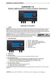
1. Basic description<br />
Tabs<br />
SIM<br />
<strong>GSM</strong> antenna<br />
SIM card<br />
RESET jumper<br />
Bus connector<br />
LED indicator<br />
Battery connection<br />
Output fuses<br />
1.1. David provides:<br />
• 2 output contacts of power relays X and Y (each allows up to 5A/250V)<br />
• 4 input terminals A to D for SMS reporting (the inputs react to a connection or disconnection<br />
to or from a common GND terminal)<br />
<strong>GD</strong>-<strong>04</strong> DAVID 12 MKS51203<br />
<strong>GD</strong>-<strong>04</strong> DAVID 1 MKS51203
1.2. David can be used as:<br />
• A switch with SMS remote control. SMS texts for switching particular terminals on/off are<br />
configurable.<br />
• A time-switch which can be activated remotely via a mobile phone (the switch-on period is<br />
configurable from 1 second to 10 hours).<br />
• A relay with dialling-in remote control. Up to 50 tel. numbers can be authorized for each<br />
relay. Because calls are not answered dialling-in control within <strong>GSM</strong> is free of charge. (David<br />
only checks the caller’s number and – if the number is authorized – responds with relay<br />
activation.) This can be used for parking latch control etc.<br />
• A relay with validity-limited dialling-in remote control. Each authorized number can have<br />
a limit to the number of calls. When the call count reaches the limit the tel. number is deauthorized.<br />
This can be useful for pre-paid services such as e.g. parking. Any tel. number can<br />
be re-authorized via SMS by the administrator.<br />
• An SMS reporter. Input A to D activations or deactivations can be reported by SMS and<br />
optionally confirmed by phone calls. Each input can have its own message texts and up to 8<br />
tel. numbers programmed.<br />
• Examples of David applications can be found on http://www.jablotron.cz/david/en/examples.htm<br />
1.3. David can be supplemented with:<br />
• A <strong>GD</strong>-<strong>04</strong>A back-up module, which provides David with the ability to work approx. 12 to 24<br />
hours continually without an external power supply, (see 11.1).<br />
• A <strong>GD</strong>-<strong>04</strong>D DTMF module, which allows you to control David’s output relays by entering<br />
numeric codes (DTMF codes) on the telephone keypad during calls, (see 11.2).<br />
• A <strong>GD</strong>-<strong>04</strong>P link cable, which allows you to connect David to a PC through a USB port and<br />
perform any desired configuration using <strong>GD</strong>Link software (see 11.4).<br />
• A <strong>GD</strong>-<strong>04</strong>R radio module, which allows input A to D activations via wireless buttons or<br />
detectors of the OASiS series and also provides David with the capability of output relay X or<br />
Y state transmission to UC or AC OASiS receivers. In addition, you can control relays X or Y<br />
“locally” via RC-8x keyfobs (so that an appliance can be controlled both via a mobile phone<br />
and a keyfob). <strong>The</strong> module also allows heating control (again locally or remotely via a mobile<br />
phone) using wireless thermostats of the TP-8x series (see 11.3).<br />
A detailed description of optional accessories can be found in chapter 11.<br />
2. David’s SIM card<br />
• In order to function, David needs a SIM card, preferably a tariffed one.<br />
• Test the SIM card by using it in your mobile phone – SMS sending and calling must work<br />
correctly.<br />
• Switch off the PIN code protection via the phone menu (or set the PIN code to 1234).<br />
• Check the <strong>GSM</strong> signal strength in David’s location.<br />
3. Installation<br />
1. <strong>The</strong> <strong>GSM</strong> antenna should not be shielded by metals. If necessary, an external antenna<br />
designed for the 900/1800MHz <strong>GSM</strong> band can be connected via a 50Ω SMA connector.<br />
2. Open the cover and release the electronic circuit board by pressing the tabs.<br />
3. Mount the rear plastic cover at the desired location.<br />
4. Insert a SIM card: Open the SIM card case by shifting the moving part in the direction of<br />
the terminals and tipping it off. Make sure that the card is correctly oriented and insert it.<br />
Close the SIM card case (fold and re-shift the moving part).<br />
<strong>GD</strong>-<strong>04</strong> DAVID 2 MKS51203<br />
Input A<br />
Input B<br />
Input C<br />
Input D<br />
Relay X<br />
Relay Y<br />
Input’s SMS reports<br />
SMS when activated<br />
SMS when deactivated<br />
Phone numbers<br />
SMS when activated<br />
SMS when deactivated<br />
Phone numbers<br />
SMS when activated<br />
SMS when deactivated<br />
Phone numbers<br />
SMS when activated<br />
SMS when deactivated<br />
Phone numbers<br />
Relays operation<br />
Wireless items *)<br />
David’s settings<br />
ON command SMS: DTMF code: *)<br />
OFF command SMS: DTMF code: *)<br />
Tel. numbers<br />
authorized for<br />
relay control<br />
ON command SMS: DTMF code: *)<br />
OFF command SMS: DTMF code: *)<br />
Tel. numbers<br />
authorized for<br />
relay control<br />
*) Only available for the <strong>GD</strong>-<strong>04</strong>D version<br />
Enrolled Type Device code Place<br />
Input A<br />
Input B<br />
Input C<br />
Input D<br />
Relay X<br />
Relay Y<br />
*) Only available for the <strong>GD</strong>-<strong>04</strong>R version<br />
<strong>GD</strong>-<strong>04</strong> DAVID 11 MKS51203
12. Specification<br />
Power supply<br />
11 – 13 V DC<br />
Stand-by consumption<br />
approx 20 mA<br />
Max. consumption (during communication)<br />
500 mA<br />
<strong>GSM</strong> band<br />
E-<strong>GSM</strong> 850 / 900 / 1800 / 1900 MHz<br />
RF output power 2 W for <strong>GSM</strong> 850 / 900, 1 W for <strong>GSM</strong> 1800 / 1900<br />
A, B, C and D input terminals activated by a connection to GND<br />
Output contact rating X1,X2 a Y1,Y2<br />
Resistive load<br />
max. 2,5A / 250V AC<br />
Inductive (capacitive), lamp load<br />
max. 0,5A / 250V AC<br />
Can be operated according to ERC/DEC/(94)01<br />
Safety EN 60950-1<br />
EMC EN 301489-7, EN 55022 and EN 50130-4<br />
Radio transmissions ETSI EN 301419-1 and EN 301511<br />
Environment<br />
II. indoor general (-10°C to +40°C)<br />
Dimensions (without antenna)<br />
76 x 110 x 33 mm<br />
<strong>GSM</strong> antenna<br />
connected to SMA connector<br />
5. Insert the circuit board back to its position.<br />
6. Do the wiring, see below.<br />
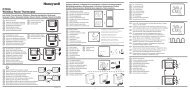
4. Wiring<br />
1. Power supply – use the +12V and GND terminals (grey<br />
colour = +12V). Any power supply adapter used should<br />
provide 12V DC voltage and up to 500mA of current. Do<br />
not turn the power supply on until all input / output wiring<br />
has been done.<br />
2. Output relay contacts – available 230V/50Hz<br />
at the X1+X2 and Y1+Y2 terminals.<br />
Each contact is fused to 5A. <strong>The</strong><br />
circuits which the contacts belong to<br />
are protected from the remaining<br />
electronics by a safety separator<br />
and are capable of switching up to<br />
2.5A at 250V AC. <strong>The</strong> following Light bulb<br />
example shows a light bulb control via the Y output relay:<br />
12V DC<br />
power supply<br />
3. Input terminals – marked A to D. <strong>The</strong> terminals respond to a<br />
connection or disconnection to or from GND by sending an SMS<br />
report. No external voltage supply can be connected to these<br />
terminals – they can only be controlled via a potential-free<br />
switch/contact. Example of wiring a switch to input A:<br />
_<br />
+<br />
Switch<br />
JABLOTRON ALARMS a.s. hereby declares that this product<br />
is in compliance with the essential requirements and other<br />
relevant provisions of Directive 1999/5/EC. <strong>The</strong> original of<br />
the conformity assessment can be found on the web site<br />
www.jablotron.com, Technical Support section.<br />
Note: Although this product does not contain any harmful<br />
materials we suggest you return the product to the dealer or<br />
directly to the manufacturer after use.<br />
5. Initial powering up<br />
1. Turn the power supply on, registering to the <strong>GSM</strong> network is indicated by the LED<br />
flashing (if no indication occurs, check the power supply wiring).<br />
2. After <strong>GSM</strong> registration the LED stops flashing (usually within 1 minute). Continued<br />
flashing indicates a <strong>GSM</strong> registration fault. Disconnect the power supply and check that a<br />
valid SIM card has been correctly installed into the device, see 2 and 3).<br />
3. Send the SMS instruction STATUS to David’s SIM card number.<br />
4. David responds by a status report, e.g. STATUS: A0,B0,C0,D0,X0,Y0,<strong>GSM</strong>:80%,<br />
Vcc:12.2V (which means that all A to D inputs and both the X and Y relays are switched off,<br />
the <strong>GSM</strong> signal strength is 80% and the power supply voltage is 12.2V). Depending on the<br />
<strong>GSM</strong> network traffic the response may take some time. If no response occurs, verify that<br />
“STATUS” is spelt exactly right in the text of the message and that you are sending the<br />
message to David’s correct SIM card number (repeat the previous step).<br />
6. Programming<br />
6.1. Via the Internet<br />
<strong>The</strong> simplest way to program David is via the web site www.david.jablotron.cz.<br />
You fill in all the required parameters in a form on a single web page, press the Send button,<br />
and the <strong>Jablotron</strong> web server will forward the settings to your David via the <strong>GSM</strong> network.<br />
Performance of a successful transfer is confirmed from David by an SMS reply "PROGRAM OK"<br />
to your mobile phone.<br />
<strong>GD</strong>-<strong>04</strong> DAVID 10 MKS51203<br />
<strong>GD</strong>-<strong>04</strong> DAVID 3 MKS51203
All parameters are sufficiently described on the page so that you do not need to use David’s<br />
installation or user manual to perform programming.<br />
Programming via the web site is free of charge. No user registration is required. Your David’s<br />
settings are not stored on the web server. Instead, you can save them as a file in your computer<br />
for future use (the file can then be imported to the page). <strong>The</strong> page does not allow you to<br />
retrieve the current settings of your David. Any programming is only possible if a valid access<br />
code (default = PC) is specified (the code, being a part of David’s settings, is not stored on the<br />
web server, only in your David). This makes the web access to your David both secure and<br />
simple.<br />
6.2. Using a PC running <strong>GD</strong>Link software<br />
If you need to program David frequently, connecting David to a PC running specialized<br />
software is the recommended option. <strong>GD</strong>Link software allows you not only to send programming<br />
instructions but also to retrieve the current David settings. For the PC connection, you can use a<br />
<strong>GD</strong>-<strong>04</strong>P link cable connected to a USB port (the cable is supplied separately). <strong>GD</strong>Link software<br />
is available either in the <strong>GD</strong>-<strong>04</strong>P’s package or on the www.jablotron.com web site.<br />
6.3. SMS instructions<br />
David can also be configured via SMS instructions from your mobile phone. <strong>The</strong> programming<br />
instruction format is explained in the following example:<br />
PC, ARX, heating on, DRX, heating off<br />
where:<br />
PC<br />
is the access (programming) code, required at the start of any programming<br />
SMS message* (2 to 8 ASCII characters, the factory default setting is PC)<br />
, is a comma separator<br />
ARX is the name of the instruction for programming the text you wish to use for<br />
switching relay X on via SMS. <strong>The</strong> desired text (“heating on”) follows, separated<br />
by a comma.<br />
DRX is similar to ARX, related to switching relay X off.<br />
<strong>The</strong> above SMS instruction tells David that the X relay can be switched on/off by the SMS<br />
instructions “heating on” / ”heating off”.<br />
Note: This text distinguishes between SMS messages and SMS instructions – an SMS message<br />
can contain multiple SMS instructions in a sequence.<br />
SMS instruction rules:<br />
1. Any programming SMS message must start with a valid access code (the factory default<br />
code is PC). Multiple messages mean multiple codes.<br />
2. A single message can contain multiple instructions. David is capable of long message<br />
processing – if enabled by your phone, you can write and send a programming SMS<br />
message containing up to 2400 ASCII characters.<br />
3. <strong>The</strong> comma separator is used both between individual instructions and between individual<br />
segments within instructions.<br />
4. Spaces are ignored, except in operational texts which are meant to be a part of a David<br />
setting.<br />
5. <strong>The</strong> successful processing of a programming SMS is confirmed from David by the SMS<br />
reply “PROGRAM OK”.<br />
6. When an error is encountered, David reports a “PROGRAM ERROR” followed by the text of<br />
the instruction which has not been recognized. Preceding instructions within the message<br />
are carried out, succeeding instructions are ignored.<br />
7. David is not case sensitive (does not distinguish between lowercase and UPPERCASE<br />
letters).<br />
<strong>GD</strong>-<strong>04</strong> DAVID 4 MKS51203<br />
• Normally, an A- or B- enrolled thermostat switches the heating (via the X or Y relay) so that<br />
temperature comfort is maintained. However, you can put the heating in economic mode<br />
by sending an SMS instruction for switching relay X or Y on, which puts the heating back to<br />
normal mode. <strong>The</strong> same can be done by connecting the A or B input to GND. <strong>The</strong> thermostat<br />
will then only provide anti-freeze protection: the heating will be switched on when a critically<br />
low temperature is signalled (e.g. 6°C). Sending an SMS instruction for switching relay X or Y<br />
off puts the heating back to normal mode (with A or B disconnected from GND).<br />
• If input A or B is used for thermostat enrollment, the status SMS report (obtained from David<br />
on an SMS request) contains information about the temperature.<br />
Example: STATUS:A0,B0,C0,D0,X1,Y0,<strong>GSM</strong>:70%,TA:25/24C,TB:22/22C, Vcc:12.2V<br />
where: TA labels data from thermostat A, TB labels data from thermostat B. <strong>The</strong> data is of<br />
the form maintained temperature / measured temperature.<br />
• Enrolling a thermostat to the A or B input disables relay X or Y enrollments.<br />
• DIP switch g setting has no effect on enrolled thermostat operation.<br />
To delete all enrolled items, press and hold buttons XY and ABCD until two long flashes<br />
occur on the red LED.<br />
11.4. <strong>The</strong> <strong>GD</strong>-<strong>04</strong>P link cable<br />
<strong>The</strong> <strong>GD</strong>-<strong>04</strong>P cable allows you to link David with a PC through an USB port and perform any<br />
desired configuration using <strong>GD</strong>Link software. <strong>The</strong> software is supplied on a CD in the package<br />
together with all the necessary drivers. You can also download <strong>GD</strong>Link from<br />
www.jablotron.com.<br />
11.4.5. Installing <strong>GD</strong>Link and the drivers<br />
1. Connect the <strong>GD</strong>-<strong>04</strong>P cable to a free USB port on your PC and insert the CD into the CD drive.<br />
2. Wait for “New Hardware Wizard“ to start up.<br />
3. Search for the drivers on the removable medium (CD).<br />
4. When installing for WIN XP, ignore the notification about wrong authenticity with WIN XP and<br />
continue with the installation process. Leave the other parameters without any modifications.<br />
5. Finish the new hardware installation wizard process.<br />
6. <strong>The</strong>re are two devices contained in one, so please wait for the “New hardware wizard” to start<br />
again. Repeat the procedure according to steps 3 to 5.<br />
7. Your PC now has two new devices after successful installation - "<strong>Jablotron</strong> serial interface" as<br />
a serial port (COM) driver and the USB device with the same name as the driver for USB.<br />
8. Install the <strong>GD</strong>Link software on your PC.<br />
9. Connect the <strong>GD</strong>-<strong>04</strong>P cable into David’s digital bus connector. <strong>GD</strong>Link is now ready to be started.<br />
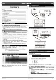
11.4.6. Using <strong>GD</strong>Link<br />
• <strong>The</strong> program allows for:<br />
o Retrieval and modification of<br />
David settings.<br />
o Displaying the last 127 memorized<br />
events.<br />
o Relays X and Y direct control.<br />
o Inputs A to D status display.<br />
• A comprehensible help option is<br />
provided as a part of the program.<br />
<strong>GD</strong>-<strong>04</strong> DAVID 9 MKS51203
esponded to by an SMS report about input activation (a connection to GND). Pressing the B<br />
button is responded to by an SMS report about input deactivation (a disconnection from GND).<br />
• For single-button controls (such as the RC-87 or RC-89), pressing the button is responded to<br />
by an SMS report about input activation.<br />
• Enrolled JA-8x detectors work with the following logic:<br />
o Input activation is reported by SMS in response to detector triggering (body movement,<br />
door opening, breaking glass, fire, tamper...)<br />
o Input deactivation is reported by SMS in response to panic signals or to the de-triggering<br />
of state-providing detectors (JA-8xM)<br />
• Wireless devices can also be assigned by entering their production code using the LRN<br />
instruction.<br />
• An input terminal with a wireless device assigned to it can be configured (see Optional functions,<br />
DIP parameter g) so that connection to GND disables the reception of wireless signals. This<br />
feature allows the setting/unsetting of enrolled detectors.<br />
11.3.3. Controlling the outputs using an RC-8x wireless button unit<br />
Each X or Y output can have four OASiS wireless button units assigned to it.<br />
1. Press and hold the XY button on the <strong>GD</strong>-<strong>04</strong>R module<br />
2. Entering enrollment mode is indicated after 5 seconds by flashing of the LED on the<br />
<strong>GD</strong>-<strong>04</strong>R module – release the button.<br />
3. Enroll up to 4 wireless button units to the X output (send enrollment signals to the<br />
module). Press the XY button again to allow enrolling to the Y output. A change of<br />
flashing rate indicates this. Wireless button units are enrolled by pressing them.<br />
Enrollment is confirmed by a long flash of the LED on the <strong>GD</strong>-<strong>04</strong>R. Important: Enrolling<br />
the first device erases all the previously enrolled devices. Thus all the desired<br />
devices should be enrolled in a single enrollment session.<br />
4. Exit enrollment mode by pressing the XY button (enrollment is automatically terminated<br />
after the fourth device has been assigned or after 40 seconds).<br />
5. After enrollment mode termination, the LED on the module lights for approx. 5 seconds to<br />
indicate enrollment data storage.<br />
6. It is possible to enroll a wireless button unit with two buttons by pressing any button(s)<br />
(A, B or A+B). Button A switches on an output, button B switches off an output and A+B<br />
changes (toggles) the status of an output (switch on – switch off). A wireless button unit<br />
with one button (RC-87 or RC-89), changes the status of an output (switch on – switch<br />
off).<br />
To delete all enrolled items, press and hold buttons XY and ABCD until two long flashes<br />
occur on the red LED.<br />
11.3.4. Using David for heating operation and status reporting<br />
Each input A–D can have a wireless thermostat of the TP-8x series assigned to it (see 11.3.2).<br />
• Enroll a thermostat to any of the A, B, C or D inputs to get reports about exceeding the<br />
maximum/minimum allowable temperature limits in your house:<br />
o Exceeding the upper temperature limit (e.g. 60°C) is responded to by an SMS report about<br />
input activation.<br />
o Dropping under the lower temperature limit (e.g. 3°C) is responded to by an SMS report<br />
about input de-activation.<br />
• Enroll a thermostat to one of the A or B inputs to take control of the temperature in your<br />
house. An A-assigned thermostat controls relay X, a B-assigned thermostat controls relay Y.<br />
This way heating control is established, supplemented by the reporting described above.<br />
<strong>The</strong>rmostats enrolled to C or D inputs only provide reporting.<br />
<strong>GD</strong>-<strong>04</strong> DAVID 8 MKS51203<br />
8. <strong>The</strong> use of accented characters is not recommended.<br />
9. After an SMS message has been received, David switches off both the X and Y relays.<br />
10. See table 1 for a brief instruction list.<br />
7. Remote operation via SMS instructions<br />
When using texts which have been programmed for David SMS operation (relay control, status<br />
interrogation) the following conditions apply:<br />
• David does not distinguish between authorized and unauthorized phones when processing<br />
operational SMS instructions. Instructions can be sent from any phones, but the texts must match the<br />
texts which have been pre-programmed (except the lowercase/UPPERCASE attribute).<br />
• Access codes are NOT part of operational SMSes.<br />
• A single SMS message can contain multiple instructions separated by commas, e.g.<br />
HEATING ON, LIGHTS OFF, STATUS<br />
• David can be so configured that every instruction performance is reported by SMS.<br />
• Received SMSes with unrecognised instructions can be forwarded to the so called service<br />
number (see table 1).<br />
• If you are not sure whether any other text will be automatically added to the SMS on its way to David<br />
(for example, when using an SMS internet gate) type the message like this: %instructions%%.<br />
Example: <strong>The</strong> SMS text “1/1 www: %heating on%%” is interpreted as heating on.<br />
8. Remote operation via dialling-in<br />
David allows you to control the X and Y relays via dialling-in from pre-authorised phones. If a<br />
call is made to David from a pre-programmed number, the call is rejected and the relay reacts as<br />
follows:<br />
o If a limit is set to the relay switch-on period then the relay switches on for the limit period.<br />
o If no limit is set (zero value is set for the limit) then the relay switches on permanently -<br />
until a switch-off SMS instruction or another dialling-in event occurs.<br />
Notes:<br />
• Up to 50 tel. numbers can be programmed for each relay.<br />
• Each tel. number can have a limit to the number of calls so that any further calls are ignored.<br />
• This feature is not applicable to phones with withheld numbers.<br />
• Dialling-in relay control can be reported by SMS.<br />
9. Using prepaid SIM cards<br />
Prepaid SIM cards are NOT recommended for use in David, because they increase the risk<br />
of David malfunctioning due to a possible credit balance under-run or expiration of the time limit.<br />
If you still decide to use a prepaid SIM card, you can configure David for periodic balance<br />
interrogation. If the reported credit balance is lower than the set limit, the credit balance<br />
message will be automatically sent to the service phone numbers. To program this feature you<br />
need to know some data specific to the <strong>GSM</strong> provider (see the SIM card documentation). <strong>The</strong><br />
programming instruction is of the following form:<br />
PC, CRD, xxxx, dd, hhh, pp<br />
where:<br />
PC is the access code<br />
CRD is the name of the instruction for credit balance interrogation<br />
xxxx is the command string to ascertain the credit (<strong>GSM</strong> network specific, e.g. *1<strong>04</strong>#)<br />
dd is the auto-interrogation frequency in days<br />
hhh is the minimum acceptable credit balance<br />
<strong>GD</strong>-<strong>04</strong> DAVID 5 MKS51203
pp<br />
is the textual position at which the number showing the balance starts in the<br />
reply message from the <strong>GSM</strong> provider<br />
Example: If you require at least 50€ of credit balance, and the USSD code used to query the<br />
available balance is *1<strong>04</strong># and you want a weekly interrogation frequency, use the following<br />
instruction:<br />
PC, CRD, *1<strong>04</strong>*#, 7, 50, 01<br />
If you do not want automatic interrogation, you can program David to report the balance in<br />
response to your SMS instruction: PC, CRD . <strong>The</strong> programming is achieved by a programming<br />
instruction according to the following example:<br />
PC, CRD, *1<strong>04</strong>*#, 0, 0, 0<br />
Note: David’s SIM card balance interrogation may stop working due to changes in <strong>GSM</strong><br />
services (e.g. a different response format). You should therefore be acquainted with the<br />
methods your <strong>GSM</strong> provider uses or will use for querying the available balance.<br />
10. Reset to factory defaults<br />
You can reset David to the factory default settings via the SMS instruction PC, RST, where PC<br />
is a valid access code - see Table 1.<br />
Another option is to use the RESET jumper (next to the SIM case):<br />
a) Turn the power supply off (including the backup module if used).<br />
b) Connect the RESET jumper, turn the power supply on and disconnect the jumper<br />
after about 5s.<br />
Note: Performing a RESET erases all programmed tel. numbers and texts.<br />
11. Optional accessories<br />
David’s functionality can be extended by optional modules or other separately supplied<br />
accessories:<br />
11.1. <strong>The</strong> <strong>GD</strong>-<strong>04</strong>A back-up module<br />
This module is imbedded in a specially-enlarged replacement cover. Installation is performed<br />
by replacing the original cover, together with wiring the <strong>GD</strong>-<strong>04</strong>A module to the <strong>GD</strong>-<strong>04</strong> circuit<br />
board via the corresponding connector.<br />
<strong>The</strong> backup battery requires approx. 72 hours to be fully charged. <strong>The</strong> battery provides<br />
approx. 12 to 24 hours of backup operation, depending on the output relay state and on the<br />
<strong>GSM</strong> signal strength (as with any <strong>GSM</strong> device, David’s consumption is higher in places with a<br />
low signal level as the transmitter power has to be increased).<br />
Only David’s electronics is backed up. No voltage is available on the +12V terminal<br />
during backup operation.<br />
Discharging the battery causes David to be switched off (including the X and Y relays). After<br />
the recovery of the main power supply David will switch on (but the relays stay switched off) and<br />
starts charging the battery. <strong>The</strong> message POWER FAIL or POWER RECOVERY is sent to the<br />
service number (STN).<br />
11.2. <strong>The</strong> <strong>GD</strong>-<strong>04</strong>D DTMF module<br />
<strong>The</strong> <strong>GD</strong>-<strong>04</strong>D allows relay X and Y control by entering numeric codes (DTMF codes) on the telephone<br />
keypad during calls. <strong>The</strong> DTMF codes intended for use have to be programmed, see table 1.<br />
<strong>The</strong> module can be installed by plugging in to the appropriate digital bus connector after the<br />
power supply has been disconnected.<br />
<strong>GD</strong>-<strong>04</strong> DAVID 6 MKS51203<br />
11.2.1. DTMF relay control<br />
• Call David’s tel. number. After about 7 seconds, David responds with a beep on the line<br />
(this means that the call has been answered) followed by relay X and Y status indication (in<br />
this order): 2 short beeps = OFF, 1 long beep = ON.<br />
• Enter the DTMF code. A relay switch-on is confirmed by a long beep, a switch-off by two short beeps.<br />
• Terminate the call (David automatically terminates the call after 60 seconds).<br />
• After the call has been terminated David reports the current relay status via SMS.<br />
Note: Too weak a <strong>GSM</strong> signal in David’s or your location may result in DTMF control<br />
malfunctions.<br />
11.3. <strong>The</strong> <strong>GD</strong>-<strong>04</strong>R radio module<br />
By plugging the <strong>GD</strong>-<strong>04</strong>R radio module into the digital bus connector (after the power supply has<br />
been disconnected) your David acquires the following capabilities:<br />
• Relay X and Y state transmission to UC or AC OASiS wireless<br />
receivers.<br />
XY ABCD<br />
• Input A to D activations via RC-8x OASiS wireless buttons or via JA-<br />
8x OASiS wireless detectors.<br />
• Relay X or Y control via RC-8x OASiS wireless buttons.<br />
<strong>GD</strong>-<strong>04</strong>R<br />
module<br />
• Relay X or Y control via a TP-8x wireless thermostat.<br />
<strong>The</strong> module has a built-in internal antenna. If necessary, a <strong>Jablotron</strong><br />
external antenna of type AN-80 or AN-81 can be applied to extend David’s remove it if<br />
working range.<br />
external antenna<br />
Note: <strong>The</strong> external antenna is always needed when the <strong>GD</strong>-<strong>04</strong>A back-up module is used.<br />
11.3.1. Transmitting X or Y relay status to an UC-82 or AC-82 receiver<br />
Enter mode 4 on the receiver and press the XY button on David’s <strong>GD</strong>-<strong>04</strong>R module. This<br />
establishes a connection so that the receiver’s relay status mirrors David’s relay status. <strong>The</strong>re is<br />
no limit to the number of UC/AC receivers which can be connected this way.<br />
11.3.2. Wireless device input assignment and operation<br />
Each input A to D can have one OASiS wireless device assigned to it. This way, triggering an<br />
external wireless device has the same effect as <strong>GD</strong>-<strong>04</strong> input activation by physical connection to<br />
GND, effectively making the inputs radio-signal-activated.<br />
Take the following steps to enroll a device:<br />
1. Press and hold the ABCD button on the <strong>GD</strong>-<strong>04</strong>R module.<br />
2. Entering enrollment mode is indicated after 5 seconds by flashing of the LED on the<br />
<strong>GD</strong>-<strong>04</strong>R module – release the button.<br />
3. Enroll up to 4 wireless devices to the <strong>GD</strong>-<strong>04</strong>R (send enrollment signals to the module). <strong>The</strong><br />
first device is assigned to the A input, the second one to the B input, etc. Wireless buttons<br />
are enrolled by pressing them, wireless detectors by inserting their batteries. Enrollment is<br />
confirmed by a long flash from the LED on the <strong>GD</strong>-<strong>04</strong>R.<br />
Important: Enrolling the first device erases all the previously enrolled devices. Thus all<br />
the desired devices should be enrolled in a single enrollment session.<br />
4. Exit enrollment mode by pressing the ABCD button (enrollment is automatically terminated<br />
after the fourth device has been assigned or after 40 seconds).<br />
5. After enrollment mode termination, the LED on the module lights for approx. 5 seconds to<br />
indicate enrollment data storage.<br />
Notes:<br />
• If the two buttons A and B are present on an RC-8x controller, the device can be enrolled by<br />
pressing either A, B or A+B. <strong>The</strong> operational logic is then as follows: pressing A or A+B is<br />
<strong>GD</strong>-<strong>04</strong> DAVID 7 MKS51203
Additional functions<br />
New access code NPC, xx…x xx…x = new access code, 2 to 8 characters<br />
Example: NPC, MARTIN27<br />
SMS to get David’s status STS, xx..x xxx..x = text, up to 30 characters<br />
Example: STS, HOW ARE YOU NOW<br />
Service tel. numbers STN, x..x, x..x xxx..x = tel. number. Up to 2 numbers can be set,<br />
previously set numbers are erased. Service<br />
numbers are used to report faults:<br />
POWER FAIL / POWER RECOVERY 1<br />
LINE OK (<strong>GSM</strong> signal recovery)<br />
THERMOSTAT FAILED lost communication<br />
LOWBATT low battery in any wireless device<br />
Other events – see Optional functions.<br />
Instruction STN, erases service number(s).<br />
Optional functions DIP,a,b,c,d,e,f,g Parameter a to f values can be:<br />
1=ON, 0=OFF, x=unchanged<br />
Description of the parameters:<br />
a Forward unrecognised SMSes to the service<br />
number (including phone number)<br />
b Periodic calls to the service number every 24<br />
hours (from the moment of being set)<br />
c Forward all SMSes to the service number<br />
d Max. 10 SMSes within 15 minutes (all<br />
subsequent SMS requests ignored)<br />
e SMS reporting of relay dialling-in-control<br />
f SMS reporting of relay SMS control (e.g.<br />
heating off OK)<br />
g Input terminal GND connection disables any<br />
wireless connection to the input (not applicable<br />
to thermostats) Example: DIP,1,x,x,x,x,1,x<br />
DTMF code to switch relay CAX, xx..x Use CAY for relay Y.<br />
ON 2 xx..x = numeric code, up to 8 digits<br />
Example: CAY, 1234<br />
Instruction CAY, erases the code.<br />
DTMF code to switch relay CDX, xx..x Use CDY for relay Y.<br />
OFF 2 xx..x = numeric code, up to 8 digits<br />
Example: CDY, 1234<br />
Instruction CDY, erases the code.<br />
Wireless device<br />
LRN,n,xx..x,n,x. n = A, B, C, D, X or Y (input or output the device<br />
assignments 3 should be assigned to)<br />
xx..x = device production code (last 8 digits)<br />
Only one device can be assigned to each A to D<br />
input, whereas each of X or Y relays can have up<br />
to 4 devices enrolled. Example: LRN,A,xx..x,B,<br />
xx..x, X,xx..x Instruction LRN, erases all<br />
assignments. A device cannot have multiple<br />
assignments. <strong>The</strong> order of A to Y is arbitrary, no<br />
duplications are allowed.<br />
Triggering re-registration to<br />
the <strong>GSM</strong> network<br />
<strong>GSM</strong><br />
David will unregister and then re-register to the <strong>GSM</strong><br />
network. This can be useful after a blocked SIM card<br />
has been unblocked. A re-registration is also triggered<br />
by briefly connecting the RESET jumper while David<br />
is being powered up.<br />
Reset RST Resets David to the factory default settings.<br />
This can also be performed by connecting the<br />
RESET jumper during powering up – disconnect<br />
the jumper after approx. 5 sec.<br />
PC<br />
STATUS<br />
none<br />
0000000<br />
(all OFF)<br />
none<br />
none<br />
none<br />
1 Only available for the <strong>GD</strong>-<strong>04</strong>A version<br />
2 Only available for the <strong>GD</strong>-<strong>04</strong>D version<br />
3 Only available for the <strong>GD</strong>-<strong>04</strong>R version
JABLOTRON ALARMS a.s.<br />
Pod Skalkou 4567/33<br />
46601 Jablonec nad Nisou<br />
Czech Republic<br />
Tel.: 483 559 911, Fax: 483 559 993<br />
Internet: www.jablotron.cz