A robust feedforward compensation scheme for multistage ...
A robust feedforward compensation scheme for multistage ...
A robust feedforward compensation scheme for multistage ...

Create successful ePaper yourself
Turn your PDF publications into a flip-book with our unique Google optimized e-Paper software.
THANDRI AND SILVA-MARTÍNEZ: ROBUST FEEDFORWARD COMPENSATION SCHEME FOR MULTISTAGE OTAS WITH NO MILLER CAPACITORS 239<br />
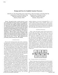
Fig. 5.<br />
NCFF <strong>compensation</strong> <strong>scheme</strong> <strong>for</strong> n-stage amplifier.<br />
and the dominant pole is located at<br />
zero is<br />
. The location of the LHP<br />
Notice that the location of the LHP zero is approximately at<br />
times the gain-bandwidth product of the first stage, where<br />
. The second and <strong>feed<strong>for</strong>ward</strong> stages can be designed<br />
such that the negative phase shift due to is compensated by<br />
the positive phase shift of the LHP zero. When the frequency of<br />
exactly coincides with that of the LHP zero, the amplifier<br />
phase margin is 90 and the unity-gain frequency is given by<br />
. The open- and closed-loop transfer<br />
functions <strong>for</strong> perfect and imperfect pole–zero cancellation are<br />
shown in Fig. 4(a) and (b), respectively. The implications of<br />
pole–zero mismatch are discussed in Section III.<br />
This <strong>compensation</strong> <strong>scheme</strong> results in an amplifier with high<br />
gain and fast response. The bandwidth improvement is due to<br />
the fact that the poles are not split, as is the case in any amplifier<br />
with Miller <strong>compensation</strong>. There can be a substantial reduction<br />
in area and power, especially as compared to <strong>multistage</strong><br />
amplifiers, which use two or more capacitors <strong>for</strong> phase <strong>compensation</strong>.<br />
If the nondominant pole of the first stage is also considered,<br />
then the resulting transfer function has three poles and two<br />
LHP zeros. In general, the number of LHP zeros created by the<br />
<strong>feed<strong>for</strong>ward</strong> path is equal to the order of the first stage. The main<br />
restriction here is that the nondominant pole of the <strong>feed<strong>for</strong>ward</strong><br />
and second stage must be placed after the overall unity-gain<br />
bandwidth of the amplifier in order to minimize phase degradation.<br />
This <strong>compensation</strong> <strong>scheme</strong> can be extended <strong>for</strong> a generic<br />
-stage amplifier, as shown in Fig. 5.<br />
III. OPTIMIZATION OF CLOSED-LOOP RESPONSE<br />
The OTA is commonly used in closed-loop configuration with<br />
feedback capacitors as shown in Fig. 1. Imperfect pole–zero<br />
cancellation results in a pole–zero doublet that might affect the<br />
(4)<br />
per<strong>for</strong>mance of the amplifier. The transconductances of individual<br />
gain stages should be selected properly to alleviate this<br />
drawback, as shown in the following discussion.<br />
It has already been shown that a pole–zero doublet may<br />
degrade the settling time according to the pole–zero spacing<br />
and the zero’s frequency [8]. The closed-loop transfer function<br />
of a capacitive amplifier is affected by the feedback factor,<br />
as shown in (1) and (2). Usually, an amplifier with open-loop<br />
phase margin of around 60 –70 gives the fastest step response<br />
<strong>for</strong> the overall amplifier [9], [10]. However, the capacitive<br />
amplifier’s pulse response in the presence of a pole–zero<br />
doublet is more complex. Let us now consider the capacitive<br />
amplifier shown in Fig. 1 using the proposed OTA. By using<br />
typical circuit analysis techniques, it can be shown that the<br />
overall closed-loop transfer function is<br />
The zero and poles are given by<br />
where and are the effective<br />
OTA load capacitor and first-stage load capacitor (see Figs. 1<br />
and 3), respectively. The parameter<br />
is the feedback factor, and<br />
Notice that<br />
(5)<br />
(6)<br />
(7)<br />
(8)<br />
is the OTA output conductance.<br />
, and that real poles are obtained if<br />
. In (5), it is assumed<br />
that the frequency of the RHP zero due to gate–drain capacitors<br />
is placed at very high frequency, which is usually the case, and