Lissajous Figures - Jed Margolin
Lissajous Figures - Jed Margolin
Lissajous Figures - Jed Margolin

Create successful ePaper yourself
Turn your PDF publications into a flip-book with our unique Google optimized e-Paper software.
<strong>Lissajous</strong> <strong>Figures</strong><br />
http://www.jmargolin.com/mtest/LJfigs.htm<br />
1 of 6 10/30/09 11:37 PM<br />
<strong>Lissajous</strong> <strong>Figures</strong><br />
by <strong>Jed</strong> <strong>Margolin</strong><br />
In the old days, whenever they showed an engineer working, there was usually an oscilloscope nearby with a<br />
pattern on the screen. Most often, the pattern was a <strong>Lissajous</strong> Figure.<br />
Jules Antoine <strong>Lissajous</strong> (1822-1880) was a French physicist who was interested in waves, and around 1855<br />
developed a method for displaying them optically by reflecting a light beam from a mirror attached to a<br />
vibrating object such as a tuning fork.<br />
You might wonder why he didn't just use an oscilloscope. It was probably because the Cathode Ray Tube<br />
hadn't been invented yet. (It was invented in 1897 by Karl Ferdinand Braun).<br />
A <strong>Lissajous</strong> figure is produced by taking two sine waves and displaying them at right angles to each other.<br />
This is easily done on an oscilloscope in XY mode.<br />
In the following examples the two sine waves have equal amplitudes.<br />
When the two sine waves are of equal frequency and in-phase, you<br />
get a diagonal line to the right .<br />
When the two sine waves are of equal frequency and 180 degrees<br />
out-of-phase you get a diagonal line to the left.
<strong>Lissajous</strong> <strong>Figures</strong><br />
http://www.jmargolin.com/mtest/LJfigs.htm<br />
2 of 6 10/30/09 11:37 PM<br />
When the two sine waves are of equal frequency and 90 degrees<br />
out-of-phase you get a circle.<br />
This should not be a big surprise, because when<br />
X = sin(a) and Y = sin(a + 90) = cos(a)<br />
X*X + Y*Y = sin(a) * sin(a) + cos(a) * cos(a) = 1<br />
which is the parametric equation for a circle having a radius of 1.<br />
If the two sine waves are in phase but the frequency of the<br />
horizontal sine wave is twice the frequency of the vertical sine wave<br />
you get the pattern shown here.
<strong>Lissajous</strong> <strong>Figures</strong><br />
http://www.jmargolin.com/mtest/LJfigs.htm<br />
3 of 6 10/30/09 11:37 PM<br />
This shows the sine wave 90 degrees out-of-phase with the frequency<br />
of the horizontal sine wave three times the frequency of the vertical<br />
sine wave.<br />
Mere static pictures do not do justice to <strong>Lissajous</strong> <strong>Figures</strong>.<br />
When the horizontal and vertical sine wave frequencies differ by a fixed amount, this is equivalent to<br />
constantly rotating the phase between them.<br />
The figure produced by this rotating phase appears to be a rotating 3D figure.<br />
In addition, as in 3D wireframe images, the figure can appear to rotate in either direction, depending on how<br />
your brain interprets it. It can also spontaneously reverse the direction of rotation. (In a real 3D wireframe<br />
image the image can also appear to rotate around a different axis.)<br />
The rotation of <strong>Lissajous</strong> <strong>Figures</strong> is something you need to see, so I am posting a program to do this.<br />
Because the sine function is computationally intensive, the program starts out by calculating a table of sine<br />
values for a complete cycle of 360 degrees. Changing the address at which the table lookup is begun produces<br />
a sine wave with a different phase. The table address is wrapped so that the value is always valid.<br />
By constantly increasing or decreasing the phase we produce the equivalent of having a small frequency<br />
difference. Technically, this is phase modulation. Large differences in frequency to produce integer multiples<br />
of frequencies are produced by multiplying the step size of the angles used to look up the sine value.<br />
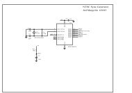
It is part of a program of Monitor Test Patterns that also produces Color Bars, a Crosshatch Pattern, a Dot<br />
Pattern, and a Monitor High Voltage Test.<br />
The Color Bars are used to evaluate how well the Monitor reproduces colors.<br />
The Crosshatch and Dot patterns are used to evaluate and adjust monitor convergence. (Don't try to adjust<br />
monitor convergence unless you know what you're doing and you have an enormous amount of patience.)<br />
The Crosshatch pattern is also used to evaluate Geometric Distortion in the Monitor.<br />
A Monitor should produce a crosshatch pattern with nice regular squares. A distorted pattern means either<br />
something is wrong or you have a crappy monitor. I once had a moderately expensive Sony TV (not a<br />
computer monitor) that exhibited noticeable geometric distortion. When I brought it to the Sony Service<br />
Center they gave me quite a run-around. It finally came down to:<br />
Sony: This TV meets all of our specifications for Geometric Distortion.<br />
Me: I would like a copy of your specifications for Geometric Distortion.<br />
Sony: We have no specifications for Geometric Distortion.<br />
Eventually, they saw the wisdom of buying the TV back from me. (I bought an inexpensive Daytron Korean
<strong>Lissajous</strong> <strong>Figures</strong><br />
http://www.jmargolin.com/mtest/LJfigs.htm<br />
TV that was my primary TV for many years and still works even now.)<br />
The High Voltage Test changes the screen brightness in order to see how well the High Voltage is regulated.<br />
When the High Voltage changes, so does the deflection sensitivity. (See my article on The Secret Life of XY<br />
Monitors if you would like an explanation.) When you are watching a TV program, it is really annoying to<br />
have the picture noticeably change size when the brightness of the scene changes. I have a newer model<br />
Magnavox TV whose High Voltage regulation sucks. I am betting on Organic LED (OLED) Displays to<br />
finally allow me to have an affordable flat panel TV with none of the design compromises that make TVs<br />
with CRTs so annoying.<br />
I have done two versions of the program:<br />
Version 1 uses OpenGL. It was compiled by Microsoft Visual C++ 6.0 and runs under Windows 9X. Support<br />
for OpenGL is built into Windows 9X. You don't have to install anything or screw around with the Operating<br />
System. All you do is run the program.<br />
There are two versions of the <strong>Lissajous</strong> Patterns: one for fast machines and one for slow machines. The<br />
reason for this is that the Timer functions available in Windows are pathetic. The fastest you can get (without<br />
special gyrations) is 50 ms. Incredibly, there appears to be no way of determining when Vertical Retrace<br />
occurs, which is the best time for switching the display buffers.<br />
My preference is that you examine the code until you understand it, then compile it yourself before running it.<br />
(Visual C++ 6.0 contains the OpenGL files you need to compile the program.)<br />
This is my first real Windows program. I adapted the framework for the program from Jeff Molofee's<br />
excellent OpenGL tutorial available at www.nehe.gamedev.net/opengl.asp .<br />
The framework is in Mtest.cpp . Any bugs are probably mine.<br />
My part of the program is in Mprog.cpp . Any bugs are definitely mine.<br />
If you do not have Visual C++, I suggest you run a virus checker on Mtest.exe before you run it. It will give<br />
us both some piece of mind.<br />
Given the problems with viruses these days, I also suggest you download it only from my Web site<br />
(www.jmargolin.com).<br />
Download Mtest.zip for Windows<br />
It should consist of the following files:<br />
Name Modified Size Ratio Packed Path<br />
Mprog.cpp 5/21/01 7:27 PM 29,487 82% 5,291<br />
Mprog.h 5/21/01 7:29 PM 3,401 64% 1,236<br />
Mtest.aps 5/13/01 1:29 PM 4,096 70% 1,215<br />
Mtest.cpp 5/21/01 7:27 PM 17,992 66% 6,180<br />
Mtest.dsp 5/17/01 10:39 AM 4,643 74% 1,200<br />
Mtest.dsw 5/13/01 1 18 PM 533 61% 210<br />
Mtest.exe 5/21/01 7:29 PM 53,248 57% 22,801<br />
4 of 6 10/30/09 11:37 PM
<strong>Lissajous</strong> <strong>Figures</strong><br />
http://www.jmargolin.com/mtest/LJfigs.htm<br />
Mtest. h 5/13/01 1 17 PM 323 51% 157<br />
Mtest. ico 5/13/01 1:17 PM 1,078 83% 180<br />
Mtest. ncb 5/21/01 7:32 PM 66,560 85% 10,299<br />
Mtest.opt 5/21/01 7:32 PM 53,760 92% 4,357<br />
Mtest. plg 5/21/01 7:29 PM 6,154 86% 880<br />
Mtest. rc 5/13/01 1:17 PM 3,056 70% 931<br />
Readme.txt 5/13/01 1 17 PM 2,055 64% 741<br />
Resource.h 5/13/01 1 17 PM 777 54% 357<br />
Small.ico 5/13/01 1 17 PM 318 71% 91<br />
Stdafx.cpp 5/13/01 1 17 PM 292 34% 192<br />
Stdafx. h 5/13/01 1 17 PM 936 49% 476<br />
18 file(s) 248,709 77% 56,794<br />
Version 2 of the program is from the original DOS version that I developed using Borland Turbo C, which<br />
was a good way to learn C. Borland Turbo C has a nice Integrated Development Environment (IDE) but it is<br />
very forgiving and allows one to develop sloppy programming habits. Its main drawback is that the best it can<br />
produce is 286 code.<br />
The version I am making available here has been updated somewhat. Mtest386.exe was compiled under<br />
Borland C 4.5 as a DOS program to produce 386 code. Mtest286.exe was compiled under Borland Turbo C<br />
to produce 286 code.<br />
You can even put it on a boot disk.<br />
I could have had the compiler produce 486 code but if you have an old 286 or 386 machine around you can<br />
keep the <strong>Lissajous</strong> Pattern running on it so people will know you are a real engineer.<br />
Download Mtest.zip for DOS<br />
It should consist of the following files:<br />
Name Modified Size Ratio Packed<br />
Chatch.c 12/10/98 9:27 PM 8,137 83% 1,386<br />
Colors.c 12/9/98 8:58 PM 6,357 80% 1,271<br />
Colors.h 12/7/98 12:24 AM 1,750 67% 578<br />
Main.c 5/21/01 8:04 PM 6,697 71% 1,960<br />
Msine.c 5/21/01 11:34 PM 5,334 66% 1,827<br />
Msine2.c 5/19/01 10:36 AM 4,417 68% 1,406<br />
Mtable.h 5/19/01 10:50 AM 2,508 64% 892<br />
Mtest286.exe 5/21/01 11:34 PM 81,715 43% 46,700<br />
Mtest386.exe 5/21/01 11:44 AM 118,974 48% 62,410<br />
9 file(s) 235,889 50% 118,430<br />
Before there were frequency counters and phase locked loops, <strong>Lissajous</strong> <strong>Figures</strong> were used to compare two<br />
frequencies (such as a reference signal to an unknown signal) that were within a few integer multiples apart.<br />
5 of 6 10/30/09 11:37 PM
<strong>Lissajous</strong> <strong>Figures</strong><br />
http://www.jmargolin.com/mtest/LJfigs.htm<br />
6 of 6 10/30/09 11:37 PM<br />
You could even get a rough estimation of the phase between the signals.<br />
Even today, there is value in taking the two channels of a stereo audio signal and connecting them to an<br />
oscilloscope in XY mode, especially if you are an FM Broadcast Station.<br />
Not everyone who listens to an FM Station is listening in stereo; it is essential to produce a compatible<br />
monaural signal. (The process by which an FM Stereo signal is produced creates a monaural signal that is the<br />
sum of the Left and Right Channels.)<br />
If, somewhere along the audio chain, the phase of one of channels is reversed, instead of getting a L+R signal,<br />
a monaural listener will hear the L-R channel. Since most announcers are placed in the center channel (L=R),<br />
the announcer will disappear.<br />
This can go completely unnoticed by operators listening with a pair of stereo monitors.(The stereo image will<br />
be screwed up as well, but is easily missed in the pressure of a broadcast operation).<br />
Connecting the Left and Right channels to an oscilloscope in XY mode will give an instant indication of the<br />
phases between the channels, since much of the material in a stereo signal is in-phase. If, when the<br />
announcer comes on, you see a 45 degree line to the right (as in the first figure in this article) you are ok. If<br />
you get a 45 degree line to the left (as in the second figure) one of your channels is out of phase. It's easy to<br />
make that kind of error when wiring a radio station. I heard one FM station broadcast for the first several<br />
hours of its first day on the air with a channel out of phase. (No, it wasn't my station.) I called them up but the<br />
operator on duty didn't know what I was talking about.)<br />
It might be interesting to program a PC to take the inputs from the sound card and display them on the screen<br />
in XY mode. Then connect the channels to an stereo FM radio and tune across the dial.<br />
It might also be interesting to program <strong>Lissajous</strong> figures and play them through the sound card.<br />
And, finally, even today with all the sophisticated graphics that people do, <strong>Lissajous</strong> <strong>Figures</strong> are still<br />
compelling to look at.<br />
Run the program in full-screen mode with the lights out and you will see why.<br />
<strong>Jed</strong> <strong>Margolin</strong><br />
San Jose, CA<br />
May 23, 2001<br />
Copyright 2001 <strong>Jed</strong> <strong>Margolin</strong><br />
Please send comments here