slide guide
slide guide
slide guide

Create successful ePaper yourself
Turn your PDF publications into a flip-book with our unique Google optimized e-Paper software.
ROTARY BALL SPLINE<br />
ROTARY BALL SPLINE<br />
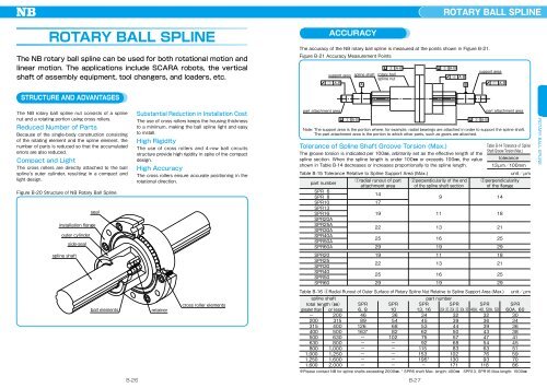
The NB rotary ball spline can be used for both rotational motion and<br />
linear motion. The applications include SCARA robots, the vertical<br />
shaft of assembly equipment, tool changers, and loaders, etc.<br />
ACCURACY<br />
The accuracy of the NB rotary ball spline is measured at the points shown in Figure B-21.<br />
Figure B-21 Accuracy Measurement Points<br />
support area<br />
1 A-B<br />
spline shaft<br />
A<br />
3 A-B<br />
rotary ball<br />
spline nut<br />
3 A-B<br />
4 A-B<br />
B<br />
support area<br />
1 A-B<br />
STRUCTURE AND ADVANTAGES<br />
The NB rotary ball spline nut consists of a spline<br />
nut and a rotating portion using cross rollers.<br />
Reduced Number of Parts<br />
Because of the single-body construction consisting<br />
of the rotating element and the spline element, the<br />
number of parts is reduced so that the accumulated<br />
errors are also reduced.<br />
Compact and Light<br />
The cross rollers are directly attached to the ball<br />
spline's outer cylinder, resulting in a compact and<br />
light design.<br />
Figure B-20 Structure of NB Rotary Ball Spline<br />
outer cylinder<br />
side-seal<br />
seal<br />
installation flange<br />
Substantial Reduction in Installation Cost<br />
The use of cross rollers keeps the housing thickness<br />
to a minimum, making the ball spline light and easy<br />
to install.<br />
High Rigidity<br />
The use of cross rollers and 4-row ball circuits<br />
structure provide high rigidity in spite of the compact<br />
design.<br />
High Accuracy<br />
The cross rollers ensure accurate positioning in the<br />
rotational direction.<br />
part attachment area<br />
2 A-B<br />
Table B-15 Tolerance Relative to Spline Support Area (Max.)<br />
2 A-B<br />
part attachment area<br />
Note: The support area is the portion where, for example, radial bearings are attached in order to support the spline shaft.<br />
The part attachment area is the portion to which other parts, such as gears are attached.<br />
Tolerance of Spline Shaft Groove Torsion (Max.)<br />
The groove torsion is indicated per 100mm, arbitrarily set as the effective length of the<br />
spline section. When the spline length is under 100mm or exceeds 100mm, the value<br />
shown in Table B-14 decreases or increases proportionally to the spline length.<br />
part number<br />
SPR 6<br />
SPR 8<br />
SPR10<br />
SPR13<br />
SPR16<br />
SPR20A<br />
SPR25A<br />
SPR30A<br />
SPR40A<br />
SPR50A<br />
SPR60A<br />
1radial runout of part<br />
attachment area<br />
14<br />
17<br />
19<br />
22<br />
25<br />
29<br />
2perpendicularity of the end<br />
of the spline shaft section<br />
9<br />
11<br />
13<br />
16<br />
19<br />
Table B-14 Tolerance of Spline<br />
Shaft Groove Torsion (Max.)<br />
tolerance<br />
13μm/100mm<br />
3perpendicularity<br />
of the flange<br />
14<br />
18<br />
21<br />
25<br />
29<br />
unit/μm<br />
ROTARY BALL SPLINE<br />
spline shaft<br />
SPR20<br />
SPR25<br />
SPR30<br />
SPR40<br />
SPR50<br />
SPR60<br />
19<br />
22<br />
25<br />
29<br />
11<br />
13<br />
16<br />
19<br />
18<br />
21<br />
25<br />
29<br />
ball elements<br />
retainer<br />
cross roller elements<br />
Table B-16 4Radial Runout of Outer Surface of Rotary Spline Nut Relative to Spline Support Area (Max.)<br />
spline shaft<br />
total length(mm)<br />
greater than or less<br />
− 200<br />
200 315<br />
315 400<br />
400 500<br />
500 630<br />
630 800<br />
800 1,000<br />
1,000 1,250<br />
1,250 1,600<br />
1,600 2,000<br />
SPR<br />
6 、8<br />
46<br />
89<br />
126<br />
163*<br />
−<br />
−<br />
−<br />
−<br />
−<br />
−<br />
SPR<br />
10<br />
36<br />
54<br />
68<br />
82<br />
102<br />
−<br />
−<br />
−<br />
−<br />
−<br />
part number<br />
SPR SPR SPR<br />
1 3 、1 6 2 0 A 、2 0 、2 5 A 、2 5 、3 0 A 、3 0 40A、40、50A、50<br />
34<br />
32<br />
32<br />
45<br />
39<br />
36<br />
53<br />
44<br />
39<br />
62<br />
50<br />
43<br />
75<br />
57<br />
47<br />
92<br />
68<br />
54<br />
115<br />
83<br />
63<br />
153<br />
102<br />
76<br />
195* 130<br />
93<br />
−<br />
171 118<br />
u nit /μm<br />
SPR<br />
60A、60<br />
30<br />
34<br />
36<br />
38<br />
41<br />
45<br />
51<br />
59<br />
70<br />
86<br />
※Please contact NB for spline shafts exceeding 2000mm. * SPR6 shaft Max. length: 400mm SPR13, SPR16 Max.length: 1500mm<br />
B-26<br />
B-27