slide guide
slide guide
slide guide

You also want an ePaper? Increase the reach of your titles
YUMPU automatically turns print PDFs into web optimized ePapers that Google loves.
SLIDE WAY<br />
STROKE<br />
INSTALLATION PROCEDURE OF NV TYPE<br />
Please contact NB for a non-standard stroke length for the NV type. When the stroke of SV type or SVW<br />
type is changed, the stroke length must be determined and the load rating should be re-estimated as follows.<br />
Stroke of SV type, SVW type<br />
When the <strong>slide</strong> way moves along the rail, the cage moves half the distance traveled by the <strong>slide</strong> way in the same<br />
direction. Therefore, although the work may be fixed on the table, the distance between the load center and the<br />
cage center will change. To achieve stable accuracy, determine the stroke and the length of the rail as follows.<br />
Figure G-8<br />
L<br />
l<br />
S2<br />
Rail Length (L)<br />
When the stroke is 400mm or over<br />
S≦L/1.5<br />
When the stroke is less than 400 mm,<br />
S≦L<br />
l: cage length(mm) S: stroke(mm)<br />
L: rail length(mm)<br />
LUBRICATION AND DUST PREVENTION<br />
Lubrication<br />
The <strong>slide</strong> way is pre-lubricated with lithium soapbased<br />
grease prior to shipment for immediate use.<br />
Make sure to relubricate with a similar type of grease<br />
periodically according to the operating conditions.<br />
NB also provides low dust generation grease. Please<br />
refer to page Eng-39 for details.<br />
Dust Prevention<br />
Foreign particles or dust in the <strong>slide</strong> way affects<br />
the motion accuracy and shortens the life time. In<br />
a harsh environment please provide side covers for<br />
dust prevention. (refer to Figure G-9)<br />
MOUNTING<br />
Example<br />
Figure G-10 NV type, SV type<br />
Accuracy of Mounting Surface<br />
To maximize the performance of the NB <strong>slide</strong> way, it<br />
is recommended that the accuracy of the mounting<br />
surface to be equal to or greater than the degree of<br />
parallelism of the <strong>slide</strong> way.<br />
Parallelism of surface 1 against surface A<br />
Perpendicularity of surface 2 against surface A<br />
Parallelism of surface 3 against surface B<br />
Perpendicularity of surface 4 against surface B<br />
Parallelism of surface 2 against surface C<br />
Parallelism of surface 4 against surface C<br />
Cage length(l)<br />
l≦L− S 2<br />
Number of rollers(Z)<br />
Z= l−2a<br />
p +1<br />
a,p: Please refer to roller cage dimensions<br />
(page G-5)<br />
Figure G-9 Example of Dust Prevention Mechanism<br />
Figure G-11 SVW type<br />
Figure G-12 Accuracy of Mounting Surface<br />
A<br />
C<br />
B<br />
1.6 1.6<br />
2 1<br />
4 4<br />
3<br />
3<br />
1.6<br />
1.6<br />
1.6<br />
1.6<br />
1.6<br />
side cover<br />
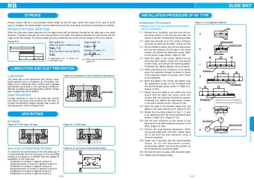
Installation Procedure<br />
※Please read“Use and Handling Precautions”<br />
before installation.<br />
( 1 )Remove burrs, scratches, and dust from the railmounting<br />
surface of the bed and the table, be<br />
careful to prevent contamination during assembly.<br />
( 2 )Apply low-viscosity oil to the contact surfaces,<br />
and align the bed and the table. (Figure G-13a)<br />
( 3 )Set the reference surface onto the mounting surface<br />
with the rails fastened. Set the table in the center<br />
position, and tighten the adjustment screws lightly<br />
so that almost no gap remains. (Figure G-13b)<br />
( 4 )Keep the table in the center, tighten the rail<br />
mounting bolts lightly, loosen the end pieces<br />
of both ends, and remove the fastening plates.<br />
Following this, lightly retighten the end pieces.<br />
( 5 )While maintaining the conditions of (4), gently<br />
move the assembly through its stroke to check<br />
if the maximum stroke is secured, and if there<br />
is no irregularity.<br />
( 6 )Move the table to the center and tighten only<br />
the adjustment screws on the R-retainer with<br />
the recommended torque shown in Table G-3.<br />
(Figure G-13c)<br />
( 7 )Gently move the table to one stroke end, and<br />
check that the table has surely come into<br />
contact with the external mechanical stopper.<br />
Following this, tighten the adjustment screws<br />
in the same manner as (6). (Figure G-13d)<br />
( 8 )Move the table to the opposite stroke end, and<br />
tighten in the same manner as (6). (Figure G-13e)<br />
( 9 )Fasten the mounting screws on rails 1, 2, and<br />
3 by tightening with the recommended torque<br />
shown in Table G-4. (Figure G-13f)<br />
(10)Set the dial indicators to the center of the<br />
table and to the side (reference surface) of the<br />
table. (Figure G-13g)<br />
(11)Perform the final preload adjustment. While<br />
moving the table back and forth, repeat steps<br />
(6) to (8) until the dial indicators show a<br />
minimum deviation.<br />
(12)Fasten rail 4 securely with the recommended<br />
to rq u e . As fo r the a djustment screws ,<br />
successively tighten the mounting screws on<br />
the R-retainer by moving the table.<br />
(13)Recheck the motion accuracy while moving the table.<br />
(14)Tighten the end pieces finally.<br />
G-6 G-7<br />
Figure G-13 Installation Method<br />
<br />
<br />
<br />
<br />
<br />
<br />
<br />
R-retainer<br />
R-retainer<br />
<br />
dial indicators<br />
end piece<br />
table<br />
bed<br />
fastening plates<br />
adjustment screws<br />
R-retainer<br />
: Adjustment screws can be tightened.<br />
: Adjustment screws should not be tightened.<br />
<br />
<br />
<br />
adjustment screws<br />
adjustment side<br />
SLIDE WAY