Data Sheet - Gamewell-FCI
Data Sheet - Gamewell-FCI
Data Sheet - Gamewell-FCI

You also want an ePaper? Increase the reach of your titles
YUMPU automatically turns print PDFs into web optimized ePapers that Google loves.
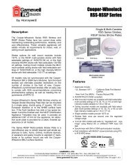
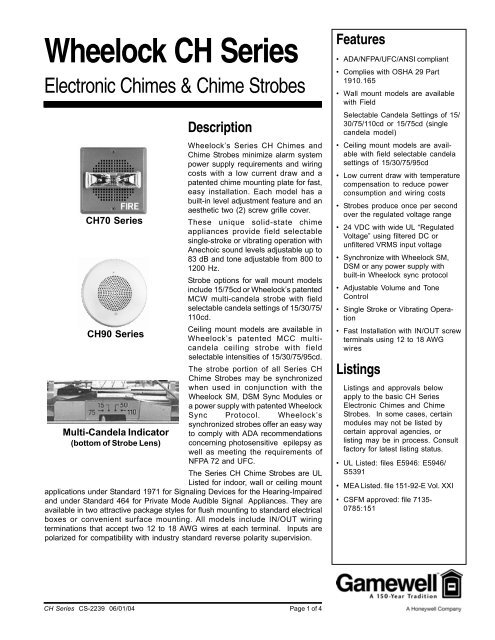
Wheelock CH Series<br />
Electronic Chimes & Chime Strobes<br />
CH70 Series<br />
CH90 Series<br />
Multi-Candela Indicator<br />
(bottom of Strobe Lens)<br />
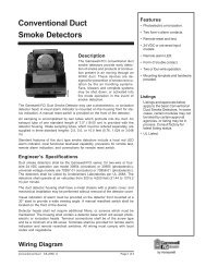
Description<br />
Wheelock’s Series CH Chimes and<br />
Chime Strobes minimize alarm system<br />
power supply requirements and wiring<br />
costs with a low current draw and a<br />
patented chime mounting plate for fast,<br />
easy installation. Each model has a<br />
built-in level adjustment feature and an<br />
aesthetic two (2) screw grille cover.<br />
These unique solid-state chime<br />
appliances provide field selectable<br />
single-stroke or vibrating operation with<br />
Anechoic sound levels adjustable up to<br />
83 dB and tone adjustable from 800 to<br />
1200 Hz.<br />
Strobe options for wall mount models<br />
include 15/75cd or Wheelock’s patented<br />
MCW multi-candela strobe with field<br />
selectable candela settings of 15/30/75/<br />
110cd.<br />
Ceiling mount models are available in<br />
Wheelock’s patented MCC multicandela<br />
ceiling strobe with field<br />
selectable intensities of 15/30/75/95cd.<br />
The strobe portion of all Series CH<br />
Chime Strobes may be synchronized<br />
when used in conjunction with the<br />
Wheelock SM, DSM Sync Modules or<br />
a power supply with patented Wheelock<br />
Sync Protocol. Wheelock’s<br />
synchronized strobes offer an easy way<br />
to comply with ADA recommendations<br />
concerning photosensitive epilepsy as<br />
well as meeting the requirements of<br />
NFPA 72 and UFC.<br />
The Series CH Chime Strobes are UL<br />
Listed for indoor, wall or ceiling mount<br />
applications under Standard 1971 for Signaling Devices for the Hearing-Impaired<br />
and under Standard 464 for Private Mode Audible Signal Appliances. They are<br />
available in two attractive package styles for flush mounting to standard electrical<br />
boxes or convenient surface mounting. All models include IN/OUT wiring<br />
terminations that accept two 12 to 18 AWG wires at each terminal. Inputs are<br />
polarized for compatibility with industry standard reverse polarity supervision.<br />
Features<br />
• ADA/NFPA/UFC/ANSI compliant<br />
• Complies with OSHA 29 Part<br />
1910.165<br />
• Wall mount models are available<br />
with Field<br />
Selectable Candela Settings of 15/<br />
30/75/110cd or 15/75cd (single<br />
candela model)<br />
• Ceiling mount models are available<br />
with field selectable candela<br />
settings of 15/30/75/95cd<br />
• Low current draw with temperature<br />
compensation to reduce power<br />
consumption and wiring costs<br />
• Strobes produce once per second<br />
over the regulated voltage range<br />
• 24 VDC with wide UL “Regulated<br />
Voltage” using filtered DC or<br />
unfiltered VRMS input voltage<br />
• Synchronize with Wheelock SM,<br />
DSM or any power supply with<br />
built-in Wheelock sync protocol<br />
• Adjustable Volume and Tone<br />
Control<br />
• Single Stroke or Vibrating Operation<br />
• Fast Installation with IN/OUT screw<br />
terminals using 12 to 18 AWG<br />
wires<br />
Listings<br />
Listings and approvals below<br />
apply to the basic CH Series<br />
Electronic Chimes and Chime<br />
Strobes. In some cases, certain<br />
modules may not be listed by<br />
certain approval agencies, or<br />
listing may be in process. Consult<br />
factory for latest listing status.<br />
• UL Listed: files E5946: E5946/<br />
S5391<br />
• MEA Listed. file 151-92-E Vol. XXI<br />
• CSFM approved: file 7135-<br />
0785:151<br />
CH Series CS-2239 06/01/04 Page 1 of 4
General Notes<br />
• Strobes are designed to flash once per second minimum over their “Regulated<br />
Voltage Range”. Note that NFPA-72 specifies a flash rate of 1 to 2 flashes per<br />
second and ADA Guidelines specify a flash rate of 1 to 3 flashes per second.<br />
• All candela ratings represent minimum effective Strobe intensity based on UL<br />
Standard 1971.<br />
• Series E Speaker Strobes and Series E Speakers are listed under UL Standard<br />
1971 for indoor use with a temperature range of 32°F to 120°F (0°C to 49°C)<br />
and maximum humidity of 85%.<br />
• “Regulated Voltage Range” is the newest terminology used by UL to identify<br />
the voltage range. Prior to this change UL used the terminology “Listed<br />
Voltage Range”.<br />
Engineering’s Specifications<br />
The chime appliances shall be Wheelock Series CH Chimes and the chime strobe<br />
appliances shall be Wheelock Series CH Chime Strobes or approved equals. The<br />
chime shall be UL Listed under Standard 464 for Audible Signal Appliances and<br />
chimes equipped with strobes shall be listed under UL Standard 1971 for Emergency<br />
Devices for the Hearing-Impaired. In addition, the strobes shall be certified to meet<br />
the requirements of FCC Part 15, Class B and shall incorporate low temperature<br />
compensation to ensure the lowest possible current consumption.<br />
All chimes shall use solid state components and shall provide field selectable single<br />
stroke or vibrating operation with volume control and tone control. All models shall<br />
have a peak Anechoic sound output of 83 dB at 10 feet and an adjustable frequency<br />
range of 800 to 1200 Hz. All inputs shall employ terminals that accept 12 to 18 AWG<br />
wire sizes.<br />
The strobe portion of the appliance shall produce a flash rate of one (1) flash per<br />
second over the Regulated Voltage Range and shall incorporate a Xenon flashtube<br />
enclosed in a rugged Lexan® lens. The strobe shall be of low current design. Where<br />
Multi-Candela Chime Strobes are specified, the strobe intensity shall have a minimum<br />
of four (4) field selectable settings and shall be rated per UL Standard 1971 at:<br />
15/30/75/110cd or 135/185cd for wall mount and 15/30/75/95cd or 115/177cd for<br />
ceiling mount. The selector switch for selecting the candela shall be tamper resistant<br />
and not accessible from the front of the appliance. The 1575 candela strobe shall be<br />
specified when 15 candela UL Standard 1971 listing with 75 candela on-axis is<br />
required (e.g. ADA compliance).<br />
When synchronization is required, the strobe portion of the appliance shall be compatible<br />
with Wheelock’s SM, DSM sync modules or any power supply with built-in<br />
Patented Wheelock Sync Protocol. The strobes shall not drift out of synchronization at<br />
any time during operation. If the sync module or Power Supply fails to operate, (i.e.,<br />
contacts remain closed), the strobe shall revert to a non-synchronized flash rate.<br />
The chime and the chime strobe appliances shall be designed for indoor surface or<br />
flush mounting. The chime and chime strobe shall incorporate a chime mounting<br />
plate with a grille cover which is secured with two screws for a level, aesthetic finish<br />
and shall mount to standard electrical hardware requiring no additional trimplate or<br />
adapter.<br />
All chime and chime strobe appliances shall be backward compatible.<br />
Wheelock products must be used within their published specifications and must be PROPERLY<br />
specified, applied, installed, operated, maintained and operationally tested in accordance with their<br />
installation instructions at the time of installation and at least twice a year or more often and in<br />
accordance with local, state and federal codes, regulations and laws. Specification, application,<br />
installation, operation, maintenance and testing must be performed by qualified personnel for<br />
proper operation in accordance with all of the latest National Fire Protection Association (NFPA),<br />
Underwriters’ Laboratories (UL), National Electrical Code (NEC), Occupational Safety and Health<br />
Administration (OSHA), local, state, county, province, district, federal and other applicable building<br />
and fire standards, guidelines, regulations, laws and codes including, but not limited to, all appendices<br />
and amendments and the requirements of the local authority having jurisdiction (AHJ).<br />
CONTACT<br />
WHEELOCK<br />
FOR THE CURRENT “INSTALLATION<br />
INSTRUCTIONS” AND “GENERAL<br />
INFORMATION” SHEET (P82380) ON<br />
THESE PRODUCTS. THESE DOCUMENTS<br />
UNDERGO PERIODIC CHANGES. IT IS<br />
IMPORTANT THAT YOU HAVE CURRENT<br />
INFORMATION ON THESE PRODUCTS.<br />
THESE MATERIALS CONTAIN IMPOR-<br />
TANT INFORMATION THAT SHOULD BE<br />
READ PRIOR TO SPECIFYING OR<br />
INSTALLING THESE PRODUCTS,<br />
INCLUDING:<br />
• TOTAL CURRENT REQUIRED BY ALL<br />
APPLIANCES CONNECTED TO SYSTEM<br />
SECONDARY POWER SOURCES.<br />
• FUSE RATINGS ON NOTIFICATION<br />
APPLIANCE CIRCUITS TO HANDLE<br />
PEAK CURRENTS FROM ALL APPLI-<br />
ANCES ON THOSE CIRCUITS.<br />
• COMPOSITE FLASH RATE FROM<br />
MULTIPLE STROBES WITHIN A<br />
PERSON’S FIELD OF VIEW.<br />
• ADDING, REPLACING OR CHANGING<br />
APPLIANCES OR CHANGING CANDELA<br />
SETTINGS WILL AFFECT CURRENT<br />
DRAW. RECALCULATE CURRENT<br />
DRAW TO INSURE THAT THE TOTAL<br />
AVERAGE CURRENT AND TOTAL PEAK<br />
REQUIRED BY ALL APPLIANCES DO<br />
NOT EXCEED THE RATED CAPACITY OF<br />
THE POWER SOURCES OR FUSES.<br />
• THE VOLTAGE APPLIED TO THESE<br />
PRODUCTS MUST BE WITHIN THEIR<br />
“REGULATED VOLTAGE RANGE”.<br />
• INSTALLATION OF 110 CANDELA<br />
STROBE PRODUCTS IN SLEEPING<br />
AREAS.<br />
• INSTALLATION IN OFFICE AREAS AND<br />
OTHER SPECIFICATION AND INSTALLA-<br />
TION ISSUES.<br />
• USE STROBES ONLY ON CIRCUITS<br />
WITH CONTINUOUSLY APPLIED<br />
OPERATING VOLTAGE. DO NOT USE<br />
STROBES ON CODED OR INTERRUPTED<br />
CIRCUITS IN WHICH THE APPLIED<br />
VOLTAGE IS CYCLED ON AND OFF AS<br />
THE STROBES MAY NOT FLASH.<br />
• FAILURE TO COMPLY WITH THE<br />
INSTALLATION INSTRUCTIONS OR<br />
GENERAL INFORMATION SHEETS<br />
COULD RESULT IN IMPROPER INSTAL-<br />
LATION, APPLICATION, AND/OR<br />
OPERATION OF THESE PRODUCTS IN<br />
AN EMERGENCY SITUATION, WHICH<br />
COULD RESULT IN PROPERTY<br />
DAMAGE AND SERIOUS INJURY OR<br />
DEATH TO YOU AND/OR OTHERS.<br />
• CONDUCTOR SIZE (AWG), LENGTH<br />
AND AMPACITY SHOULD BE TAKEN<br />
INTO CONSIDERATION PRIOR TO<br />
DESIGN AND INSTALLATION OF THESE<br />
PRODUCTS, PARTICULARLY IN<br />
RETROFIT INSTALLATIONS.<br />
Page 2 of 4<br />
CH Series CS-2239 06/01/04
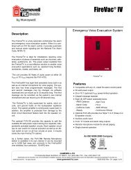
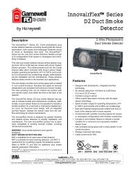
Wiring Diagram<br />
SERIES CH CHIME & STROBE<br />
OPERATE INDEPENDENTLY<br />
(NON-SYNC OR SYNC)<br />
+<br />
FROM<br />
PRECEDING<br />
APPLIANCE,<br />
SYNC MODULE, -<br />
POWER SUPPLY<br />
OR FACP<br />
FROM<br />
PRECEDING<br />
APPLIANCE,<br />
SYNC MODULE,<br />
POWER SUPPLY<br />
OR FACP<br />
STROBE<br />
(OPTIONAL)<br />
- +<br />
+<br />
COM<br />
CHIME<br />
+<br />
-<br />
+ -<br />
+ -<br />
TO NEXT<br />
APPLIANCE<br />
OR EOLR<br />
TO NEXT<br />
STROBE OR<br />
EOLR<br />
DSM #1<br />
SERIES CH CHIME STROBES<br />
SYNCHRONIZED W/ MULTIPLE<br />
DSM MODULES<br />
Note: Figure shows interconnection to<br />
strobe through sync module. Chime<br />
portion requires 2 separate conductors to<br />
FACP.<br />
F<br />
A<br />
C<br />
P<br />
Strobe NAC Cir.<br />
Strobe NAC Cir.<br />
Strobe NAC Cir.<br />
Sync<br />
+<br />
-<br />
DSM #2<br />
Sync<br />
+ -<br />
DSM #3<br />
Sync<br />
+<br />
-<br />
CH<br />
CH<br />
CH<br />
CH<br />
CH<br />
CH<br />
DSM Interconnecting wiring shown. Maximum of<br />
twenty (20)<br />
DUAL SYNC MODULE<br />
SYNC<br />
SYNC<br />
+<br />
-<br />
SERIES CH CHIME STROBE<br />
APPLIANCES SYNCHRONIZED<br />
WITH DSM MODULE SINGLE<br />
“CLASS A”<br />
F<br />
A<br />
C<br />
P<br />
+<br />
-<br />
SIGNAL<br />
CIRCUIT OUT<br />
+<br />
+<br />
+<br />
-<br />
OUT1<br />
IN1<br />
MINUS1<br />
AUDIBLE<br />
AUDIBLE<br />
+<br />
-<br />
+ OUT2<br />
+ IN2<br />
MINUS2<br />
+ -<br />
APPLIANCE<br />
+ -<br />
APPLIANCE<br />
SIGNAL<br />
CIRCUIT RETURN<br />
CH Series CS-2239 06/01/04 Page 3 of 4
NOTE: All CAUTIONS and WARNINGS are identified by the symbol . All warnings are printed in bold capital<br />
letters. PLEASE READ THESE SPECIFICATIONS AND ASSOCIATED INSTALLATION INSTRUCTIONS CAREFULLY BEFORE USING, SPECI-<br />
FYING OR APPLYING THIS PRODUCT. FAILURE TO COMPLY WITH ANY OF THESE INSTRUCTIONS, CAUTIONS OR WARNINGS COULD<br />
RESULT IN IMPROPER APPLICATION, INSTALLATION AND/OR OPERATION OF THESE PRODUCTS IN AN EMERGENCY SITUATION,<br />
WHICH COULD RESULT IN PROPERTY DAMAGE, AND SERIOUS INJURY OR DEATH TO YOU AND/OR OTHERS.<br />
Ordering Information<br />
MODEL<br />
STROBE<br />
CANDELA<br />
NON-<br />
SYNC<br />
SYNC<br />
W/SM,<br />
DSM<br />
MODEL<br />
COLOR<br />
WALL/<br />
CEILING<br />
MOUNT<br />
MOUNTING<br />
OPTIONS**<br />
AGENCY APPROVALS<br />
UL MEA CSFM BFP<br />
CH70-24MCW-FR 15/30/75/110 X X Red Wall L,O,P,Q,U,Y X X X X<br />
CH70-24MCW-FW 15/30/75/110 X X White Wall L,O,P,Q,U,Y X X X X<br />
CH70-241575W-FR 15 (75 on Axis) X X Red Wall L,O,P,Q,U,Y X X X X<br />
CH90-24MCC-FW 15/30/75/95 X X White Ceiling L,O,P,Q,U,V,Y X * X *<br />
CH70-24-R - X X Red Wall/Ceiling L,O,P,Q,U,V,Y X X X X<br />
CH90-24-W - X X White Wall/Ceiling L,O,P,Q,U,V,Y X X X X<br />
* Average RMS Current is per UL average RMS method and Average Mean Current is per UL average mean method. For rate In Rush and Peak current across the UL<br />
listed voltage range for both filtered DC and unfiltered VRMS (FWR), see installation instructions.<br />
** Refer to mounting options data sheet.<br />
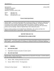
TABLE 1: AVERAGE RMS CURRENT*<br />
CH70/C90<br />
CH70 STROBE CURRENT - WALL M OUNT<br />
CH90 STROBE CURRENT - CEILING MOUNT<br />
CHIMES 241575W<br />
24MCW<br />
24MCWH<br />
24MCC<br />
24MCCH<br />
15/75cd 15cd 30cd 75cd 110cd 135cd 185cd 15cd 30cd 75cd 95cd 115cd 177cd<br />
16 vdc 0.101 0.062 0.102 0.192 0.265 0.300 0.420 0.068 0.112 0.211 0.292 0.300 0.420<br />
24 vdc 0.064 0.041 0.065 0.116 0.155 0.195 0.270 0.045 0.072 0.128 0.171 0.195 0.270<br />
33 vdc 0.047 0.032 0.047 0.081 0.107 0.145 0.190 0.035 0.052 0.089 0.118 0.145 0.190<br />
TABLE 2: CHIME dBA RATINGS<br />
CH70/CH90<br />
SOUND LEVEL<br />
PEAK<br />
dBA<br />
@ 10 ft.<br />
ANECHOIC<br />
dBA @ 10 ft.<br />
REVERBERANT<br />
Min<br />
Max<br />
83 52 58<br />
Application<br />
1. The chimes are factory set in single stroke (SS) mode. They can be<br />
changed to vibrating (VIB) mode with jumper on PC Board. SINGLE STROKE<br />
OPERATION: The minimum input pulse duration must be at least 160 ms “on”<br />
time and 160 ms “off” time. The chime will only operate once each time it is<br />
pulsed. This mode is recommended for coded systems. VIBRATING OP-<br />
ERATION: Continuous input voltage applied to the chime will activate the<br />
chime at one-second intervals.<br />
2. The volume and tone controls have been adjusted at the factory to insure<br />
maximum dBA output. However, once the mode is selected, the installer<br />
may want to fine-tune the signal to better suit the application.<br />
3. Anechoic dBA is measured in an anechoic chamber with peak meter response.<br />
Reverberant dBA is rated per UL Standard 464.<br />
4. Chime inrush current is 0.100 amps maximum with filtered DC input (0.140<br />
amps with VRMS input voltage) with a time duration of 100 milliseconds.<br />
SYNC M ODELS/POWER SUPP LY<br />
The <strong>Gamewell</strong> Company<br />
12 Clintonville Road<br />
Northford, CT 06472-1610<br />
Phone: 203-484-7161<br />
Fax: 203-484-7118<br />
www.gamewell.com<br />
A Honeywell Company<br />
© 2004 <strong>Gamewell</strong><br />
MODEL<br />
NUM BER<br />
Specifications and wiring information are provided for information only and are believed<br />
to be accurate. <strong>Gamewell</strong> assumes no responsibility for their use.<br />
<strong>Data</strong> and design are subject to change without notice. Installation and wiring<br />
instructions shipped with the product shall always be used for actual installation. For<br />
more information, contact <strong>Gamewell</strong>.<br />
Page 4 of 4<br />
IN P UT<br />
VOLTAGE<br />
(VDC)<br />
AVERAGE<br />
MEAN<br />
CURRENT<br />
@ 24 VDC<br />
MOUNTING<br />
OPTIONS<br />
SM -12/24-R 24 .028 W<br />
DSM -12/24-R 24 .035 W<br />
SM Sync Module is rated for<br />
3.0 amperes @ 24 VDC.<br />
DSM Sync Module is rated<br />
for 3.0 amperes per circuit.<br />
The maximum number of<br />
interconnected DSM<br />
modules is twenty (20).<br />
CH Series CS-2239 06/01/04