Air Brake Manual
Air Brake Manual
Air Brake Manual

You also want an ePaper? Increase the reach of your titles
YUMPU automatically turns print PDFs into web optimized ePapers that Google loves.
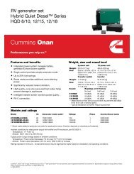
Automatic Trailer Supply Valve System<br />
The diagram below illustrates air being piped from<br />
the dry reservoir line to the trailer supply valve (28).<br />
The tractor protection valve (24) is fed by two lines:<br />
one from the trailer supply valve (28) and one from<br />
the two-way check valve (26). Leading off from the<br />
tractor protection valve are two lines, each with a<br />
glad hand coupler (20). These two lines are referred<br />
to as the control (service) line (22) and the supply<br />
(emergency) line (21).<br />
28 26<br />
24<br />
22 21<br />
20<br />
In the diagrams the upper line is the control (service)<br />
line (22) and the lower line is the supply (emergency)<br />
line (21).<br />
Illustrated is a tractor equipped with a trailer supply<br />
valve (28) and a tractor protection valve (24). The<br />
trailer is not coupled and the tractor is being<br />
operated alone (“bobtailing”). The driver has not<br />
opened the trailer supply valve (28) and the hand<br />
valve (30) is closed.<br />
30 28<br />
26<br />
24<br />
22 21<br />
20<br />
31<br />
44