specs-V-Dosc-1002-GB revised 31012003.qxd
specs-V-Dosc-1002-GB revised 31012003.qxd
specs-V-Dosc-1002-GB revised 31012003.qxd

You also want an ePaper? Increase the reach of your titles
YUMPU automatically turns print PDFs into web optimized ePapers that Google loves.
V-DOSC®<br />
THE INCREDIBLE INNOVATION OF<br />
WAVEFRONT<br />
SCULPTURE<br />
TECHNOLOGY ®<br />
L-ACOUSTICS ® V-DOSC ® is the first full<br />
frequency line source array based on the<br />
principles of Wavefront Sculpture<br />
Technology ® (WST). At the heart of<br />
V-DOSC is the internationally patented<br />
DOSC waveguide which permits fulfilment<br />
of WST criteria at high frequencies, allowing<br />
elements to couple coherently and create a<br />
single, continuous, isophasic sound source.<br />
As a result, V-DOSC is a full-spectrum coherent<br />
system, whereas conventional horn and<br />
driver assemblies interfere throughout most<br />
of their operating bandwidth. By creating a<br />
continuous radiating ribbon, V-DOSC functions<br />
as a line source array in comparison<br />
with other line arrays that do not satisfy<br />
WST criteria at high frequencies.<br />
A turnkey V-DOSC system consists of<br />
V-DOSC elements, dedicated rigging, SB218<br />
subwoofers, dV-DOSC fill enclosures, digital<br />
signal processors with proprietary OEM<br />
factory presets, V-DOSC amplifier racks and<br />
associated loudspeaker plus signal distribution<br />
cabling. A proprietary return snake system<br />
including panels and multicore is also<br />
available.<br />
The 90 degree horizontal coverage and<br />
coplanar symmetry of V-DOSC provides<br />
excellent stereo imaging in left-right configurations<br />
while WST flexibility allows the<br />
designer to cover virtually any room geometry.<br />
Well-defined vertical and horizontal<br />
directivity allows accurate performance prediction<br />
with easy-to-use software tools and<br />
by using calibrated angle values, a V-DOSC<br />
array is physically configured as a variable curvature<br />
line source array to match vertical<br />
directivity to the audience. The end result is<br />
predictable coverage, exceptionally even<br />
frequency response and SPL along with the<br />
elimination of comb filtering, phasing and<br />
lobing problems associated with conventional<br />
arrays.<br />
The unique attenuation properties of<br />
V-DOSC (3 dB reduction in SPL with<br />
doubling of distance) are obtained through<br />
cylindrical wave generation plus proper<br />
focus of the system. Nearfield extension is an<br />
associated benefit that helps maintain tonal<br />
balance with distance while extending the<br />
critical distance in a given venue. This<br />
provides improved fidelity and excellent<br />
intelligibility even under highly reverberant<br />
acoustic conditions.<br />
As a full range 3-way system, V-DOSC can<br />
be used in corporate, classical or theatrical<br />
productions without subwoofers. For<br />
touring applications, the addition of SB218<br />
subwoofers is recommended and V-DOSC<br />
is highly suited for sound reinforcement in<br />
theatre, arena, stadium or outdoor festival<br />
applications.<br />
V-DOSC has revolutionized the loudspeaker<br />
industry by providing the sound engineer<br />
with an effective and versatile sound<br />
reinforcement tool. All elements of the<br />
V-DOSC system have been selected for<br />
their quality and durability and there is a<br />
strong emphasis placed on complementary<br />
technical support and training.<br />
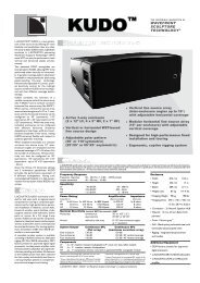
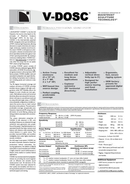
! Active 3-way<br />
enclosure<br />
(2 x 15" LF,<br />
4 x 7" MF,<br />
2 x 1.4" HF)<br />
! WST-based line<br />
source design<br />
! Perfect coupling,<br />
predictable<br />
coverage<br />
! Excellent for<br />
medium and<br />
long throw<br />
applications<br />
! Coplanar<br />
symmetry<br />
(90° horizontal<br />
directivity)<br />
! Adjustable<br />
vertical directivity<br />
(up to 5°)<br />
! Designed for<br />
high performance<br />
touring<br />
and fixed<br />
installation<br />
Frequency Response<br />
Frequency response 50 - 18k Hz (±3 dB)) (3WX HI preset)<br />
Usable bandwidth 40 - 20k Hz (-10 dB)<br />
Sensitivity 1<br />
LF 100 dB SPL 40 - 200 Hz<br />
MF 105 dB SPL 200 - 1.3kHz<br />
HF 108 dB SPL 1.3 - 18 kHz<br />
Power Rating 2 Amplification Impedance<br />
(Long Term) (Recommended) (Nominal)<br />
LF 2 x 54 Vrms 2x 375 Wrms 2 x 1500 Wpeak 2x 750 W 2x 8 ohms<br />
MF 69 Vrms 600 Wrms 2400 Wpeak 1200 W 8 ohms<br />
HF 58 Vrms 200 Wrms 800 Wpeak 800 W 16 ohms<br />
Nominal Directivity (-6dB) 3<br />
Horizontal symmetrical 90°<br />
Vertical<br />
defined by the array<br />
System Output 4 Continuous SPL Continuous SPL<br />
(flat array) (maximum curvature array)<br />
One enclosure 134 dB 134 dB<br />
Two enclosures 140 dB 139 dB 5° vertical coverage<br />
Four enclosures 146 dB 143 dB 15° vertical coverage<br />
Components<br />
LF 2 x 15" weather-resistant loudspeaker (3" voice coil, bass-reflex loaded)<br />
LF 4 x 7" weather-resistant loudspeaker (kevlar cone body, bass-reflex loaded)<br />
HF 2 x 1.4" compression driver mounted on patented DOSC waveguide<br />
! Ergonomic,<br />
fast, secure<br />
rigging system<br />
! OEM factory<br />
presets for<br />
approved digital<br />
processors<br />
L-ACOUSTICS specifications are based on measurement procedures which produce unbiased results and allow for realistic performance prediction and simulations.<br />
Some of these specifications will appear very conservative when compared with other manufacturer’s specifications. All measurements are conducted under free<br />
field conditions and scaled to a 1 m reference distance unless otherwise indicated.<br />
1 Sensitivity is the average SPL measured over the component’s<br />
rated bandwidth<br />
3 Power rating displays the long term RMS power handling<br />
capacity using pink noise with a 6 dB crest factor over the<br />
component’s rated bandwidth<br />
3 Directivity is averaged over the 1-10 kHz range<br />
4 System Output gives the unweighted SPL output of the<br />
system referenced to 1 m, including preset equalization and<br />
band leveling adjustment as measured under freefield conditions<br />
using the 3W LO preset<br />
Enclosure<br />
• Width 1300 mm 51.2 in<br />
• Height 434 mm 17.1 in<br />
• Depth 565 mm 22.2 in<br />
• Weight (net) 108 kg 238.1 lbs<br />
• Shipping weight 122 kg 269 lbs<br />
• Shipping dims 1340 x 480 x 600 mm<br />
52.8 x 18.9 x 23.6 in<br />
• Connectors : 2x 8-pin CA-COM<br />
• Material : 15 mm, 30 mm Baltic birch<br />
plywood<br />
• Finish : Maroon-gray<br />
• Grill : Black epoxy perforated steel with<br />
acoustically-transparent foam<br />
• Rigging : Integrated flying hardware<br />
and handles<br />
Additional Equipment<br />
• OEM factory presets for approved<br />
digital processors<br />
• L-ACOUSTICS SB218 subwoofer<br />
• L-ACOUSTICS LA48a power amplifier<br />
L-ACOUSTICS ® , ARCS ® , V-DOSC ® and Wavefront Sculpture Technology ® are registered trademarks
The enclosure shall be an active, 3-way loudspeaker containing two direct<br />
radiating, bass reflex-loaded 15-inch low frequency transducers, four bass<br />
reflex-loaded 7-inch midrange frequency transducers that are mounted in a<br />
V-shaped configuration and two 1.4'' exit, titanium diaphragm compression<br />
drivers that are coupled to individual, vertically-aligned waveguides. As a full<br />
range system, the frequency response shall be 50 Hz to 18 kHz with less than<br />
± 3 dB variation and the usable bandwidth shall be 40 Hz to 20 kHz (-10 dB).<br />
The waveguide employed in the loudspeaker shall generate a flat, isophasic<br />
wavefront for the high frequency section. When vertically arrayed, multiple<br />
loudspeakers shall function according to the principles of Wavefront Sculpture<br />
Technology whereby the separation between acoustic centers of individual<br />
sound sources shall be less than the size of half the wavelength at the highest<br />
frequency of their operating bandwidth or the sum of the individual areas of<br />
the isophasic radiating elements shall be greater than 80 percent of the<br />
target radiating area. Components shall be configured in a coplanar symmetric<br />
arrangement and provide 90-degree horizontal coverage (-6 dB points)<br />
independent of the number of vertically arrayed elements.<br />
Crossover points shall be 200 Hz between low and midrange sections and<br />
1.3 kHz between midrange and high sections with 24 dB per octave Linkwitz-<br />
Riley characteristics. Long term power handling shall be 2 x 375 Wrms,<br />
600 Wrms and 200 Wrms for low, midrange and high sections, respectively.<br />
Low frequency transducers shall be powered individually at a nominal<br />
8-ohm impedance, midrange frequency transducers shall be connected in<br />
series/parallel at a nominal 8-ohm impedance and high frequency transducers<br />
shall be connected in series at a nominal 16-ohm impedance. Connection to<br />
the loudspeaker shall be made via two parallel 8-pin connectors.<br />
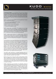
The enclosure shall have rectangular shape. Dimensions shall be 130 cm<br />
(51.2-in) wide, 43.4 cm (17.1-in) high, 56.5 cm (22.2-in) deep. Enclosure<br />
weight shall be 108 kg (238.1 lbs). Cabinet construction shall consist of 15 mm<br />
(0.59-in), 30 mm (1.18-in) Baltic birch plywood with internal steel bracing and<br />
joints that are sealed, screwed and rabbeted. The finish shall be maroon-gray,<br />
high-resilient paint. The front of the enclosure shall be protected by a black<br />
epoxy-coated, 1.5 mm (0.06-in) thick steel grille that is covered with 10 mm<br />
(0.4-in) thick acoustically-transparent open cell foam.<br />
Loudspeaker enclosures shall be installed using a dedicated rigging bumper and<br />
rigging accessories. The enclosure shall have two recessed flytrack sections<br />
mounted on both sides and two rear-mounted rigging components that allow<br />
up to 16 enclosures to be assembled in a vertical column with variable angles<br />
between enclosures up to a maximum of 5.5 degrees at 0.75 degree angular<br />
resolution.<br />
The loudspeaker shall be used with an approved digital processor with OEM<br />
factory presets for active 3-way or 4-way operation in conjunction with<br />
additional subwoofer enclosures.<br />
The loudspeaker system shall be the L-ACOUSTICS V-DOSC.<br />
The subwoofer system shall be the L-ACOUSTICS SB218.<br />
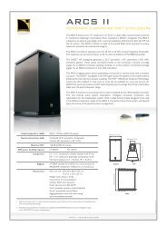
BOTTOM<br />
FRONT<br />
TOP<br />
ACCESSORIES<br />
DOSCOVx2: 2 x protective covers for V-DOSC element<br />
V-CABLE: 8 conductor loudspeaker cable: 7 m (DO7), 25 m<br />
(DO25) or 0.7 m (DO.7) lengths<br />
BUMP2:<br />
Flying / stacking bumper including accessories<br />
BUMPDELTA: Used in conjunction with 2 rear motors to adjust<br />
the horizontal pan of a flown V-DOSC array<br />
BUMPxx: Angle straps (BUMP24=0.75°/5.5°, BUMP251=1.3°,<br />
BUMP25=2°, BUMP26=3°, BUMP27=4°)<br />
SPACxx: Spacer blocks for use with angle straps.(SPAC251=1.3°;<br />
SPAC25=2°; SPAC26=3°; SPAC27=4°; SPAC28 =5.5°)<br />
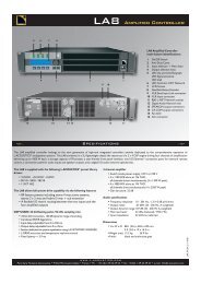
RK124:<br />
Turnkey amplifier rack containing 4 L-ACOUSTICS<br />
LA48a amplifiers, PAD04, power distribution panel<br />
RK122:<br />
Turnkey amplifier rack containing 2 L-ACOUSTICS<br />
LA48a amplifiers, PAD02, power distribution panel<br />
PAD04:<br />
Amp panel for 4 amplifier per rack configurations<br />
PAD02:<br />
Amp panel for 2 amplifier per rack configurations<br />
CO24:<br />
Control output panel for signal distribution from<br />
FOH drive rack<br />
MD24:<br />
Multi distro panel for signal distribution to amplifier racks<br />
CD12:<br />
Control distro panel for standalone applications<br />
MC28100: 28 pair multiconductor snake for use with CO24,<br />
MD24 (100 m length)<br />
DOM2, DOM30: 6 pair signal modulation cable, 2 m length (DOM2)<br />
or 30 m length (DOM30)<br />
LINK-EXTEND: male/male adapter for use with DOM2, DOM30<br />
LINK-BREAKOUT: 6 pair breakout to male XLR (DOMM)<br />
LINK-BREAKOUT: 6 pair breakout to female XLR (DOMF)<br />
CHARIOT: Transport accessory for 2 x BUMP2 plus accessories,<br />
BUMPxx angle straps, 2 x SB218 rigging bars<br />
SCALE 1:10<br />
RIGHT SIDE<br />
REAR<br />
LEFT SIDE
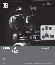
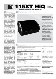
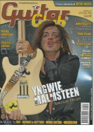
V-DOSC ®<br />
SYSTEM<br />
ACCESSORIES<br />
AMP PANEL PADO4<br />
AMP RACK RKI2U<br />
CONTROL OUTPUT CO24<br />
MULTI DISTRO MD24<br />
BUMPER2<br />
ANGLE STRAPS<br />
SPACER<br />
DELTA PLATE<br />
AMP PANEL PADO2<br />
CHARIOT
WAVEFRONT SCULPTURE TECHNOLOGY ®<br />
The first task of sound engineers and audio consultants is to design sound<br />
reinforcement systems for a predefined audience area. As measuring techniques<br />
advance and speaker systems perform better, requirements in terms<br />
of clarity, coherence, sound pressure level and consistency are increasing<br />
while at the same time the size of the audience area is growing.<br />
This inevitably leads to an increase in the number of loudspeakers. A common<br />
practice is to configure many loudspeakers in arrays or clusters in order to<br />
achieve the required SPL. The result for most sound reinforcement systems<br />
is that the sound waves radiated by individual loudspeakers do not couple<br />
properly and interfere uncontrollably. This creates non-uniform coverage,<br />
inconsistency in frequency response, poor intelligibility and reduced overall<br />
sonic quality. The chaotic sound fields created by these interfering sound<br />
sources also wastes acoustic energy, thus requiring more total power than a<br />
single, coherent source in achieving the same desired SPL.<br />
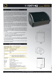
As an illustration of this principle, imagine throwing some pebbles in a pool<br />
of water. If one pebble is thrown into the water, circular waves will expand<br />
concentrically from the point where it entered. If a handful of pebbles are<br />
thrown into the water, we can observe the equivalent of a chaotic wavefield.<br />
If we throw in a single larger stone, having total size and weight equal to the<br />
handful of pebbles, then we again see circular waves as in the case of the single<br />
pebble - only now with a larger amplitude.<br />
A Single Sound Source From Many Speakers<br />
This leads to the thinking behind the development of Wavefront Sculpture<br />
Technology ® (WST). If we can construct a single sound source emanating<br />
from many speakers (which can then be separated for ease of handling and<br />
transport), then we have achieved the goal of providing a totally coherent, predictable<br />
wavefield.<br />
Line arrays have been regarded as the best approach to serve the diverse requirements<br />
of covering large audience fields. However, until now it has not been<br />
possible to make a line array operate properly because of:<br />
1) the interference produced by multiple sound sources radiating over the same<br />
coverage area, and<br />
2) an inability to achieve proper line array coupling in the high-frequency range.<br />
The initial specification of the research and development program was the design<br />
of a single acoustic source that is completely modular and adjustable. In<br />
1988, an early L-ACOUSTICS system called "Incremental" proved the project's<br />
feasibility. Based on this experimental concept, Professor Marcel Urban and<br />
Dr. Christian Heil began theoretical research and presented their findings at<br />
the 92nd AES Convention in Vienna in 1992 (Preprint # 3269). The theory that<br />
was developed defines the acoustic coupling conditions for successfully<br />
arraying individual sound sources - including wavelength, the shape of each<br />
source, their surface areas and their relative separation.<br />
Briefly, the coupling conditions can be summarized as follows:<br />
An assembly of individual sound sources arrayed following a regular step distance<br />
on a planar or curved continuous surface is equivalent to a single sound<br />
source having the same dimensions as the total assembly if one or both of the<br />
following two conditions are fulfilled :<br />
1) Frequency : The step distance (distance between the acoustic centers of<br />
individual sources) is smaller than half the wavelength over the operating<br />
bandwidth.<br />
2) Shape : The wavefronts generated by individual sources are planar and together<br />
fill at least 80 percent of the total radiating surface area.<br />
Additional WST Criteria were presented in the AES preprint entitled<br />
''Wavefront Sculpture Technology'' (111th Convention, NYC, Sept 2001,<br />
preprint # 5488). The first two WST Criteria were re-derived based on an<br />
intuitive approach using Fresnel analysis and in addition it was shown that:<br />
3) The deviation from a flat wavefront must be less than l/4 wavelength at the<br />
highest operating frequency (this corresponds to less than 5 mm curvature at<br />
16 kHz)<br />
4) For curved arrays, enclosure tilt angles should vary in inverse proportion<br />
to the listener distance (geometrically this is equivalent to shaping variable curvature<br />
arrays to provide equal spacing of individual element impact zones)<br />
5) Limits exist concerning the vertical size of each enclosure, the minimum listener<br />
distance and the relative tilt angles that are allowed between enclosures.<br />
L-ACOUSTICS defines the practical implications of these criteria as Wavefront<br />
Sculpture Technology (WST). WST dictates the design constraints for achieving<br />
a single sound source with respect to speaker component arrangement<br />
at lower frequencies. By loading the high-frequency drivers with the patented<br />
L-ACOUSTICS "DOSC" waveguide it is possible to meet the second WST<br />
condition at higher frequencies. By satisfying WST criteria over the entire audio<br />
bandwidth, the engineer or designer is provided with a "single" loudspeaker<br />
with well-defined coverage and wavefront shape, thus allowing the geometrical<br />
distribution of energy to be precisely installed to match the geometry<br />
of the audience seating area.<br />
L-ACOUSTICS V-DOSC ® , ARCS ® and dV-DOSC TM are true arrayable systems.<br />
V-DOSC and dV-DOSC are designed for large audiences and long-throw<br />
applications while ARCS is suitable for medium-throw needs. All use the<br />
heart of Wavefront Sculpture Technology - the patented DOSC Waveguide -<br />
to achieve remarkable results.<br />
Specifications subject to change without notice Specs V-DOSC 0103<br />
2201 East Celsius Avenue, Suite C<br />
Oxnard, CA 93030 • USA<br />
Ph: +1 (805) 604 0577<br />
Fax: +1 (805) 604 0858<br />
info@l-acoustics-us.com • www.l-acoustics-us.com<br />
Parc de la Fontaine de Jouvence<br />
91462 Marcoussis Cedex • France<br />
Ph:+33 (0) 1 69 63 69 63<br />
Fax: +33 (0) 1 69 63 69 64<br />
info@l-acoustics.com • www.l-acoustics.com<br />
16 Dews Road • Salisbury<br />
Wiltshire, SP2 7SN • UK<br />
Ph: +44 (0) 1722 411 234<br />
Fax: +44 (0) 1722 411236<br />
info.uk@l-acoustics.com • www.l-acoustics.com