Lee Valley Tools - Veritas Tool Chest Locking Spring Pins
Lee Valley Tools - Veritas Tool Chest Locking Spring Pins
Lee Valley Tools - Veritas Tool Chest Locking Spring Pins

You also want an ePaper? Increase the reach of your titles
YUMPU automatically turns print PDFs into web optimized ePapers that Google loves.
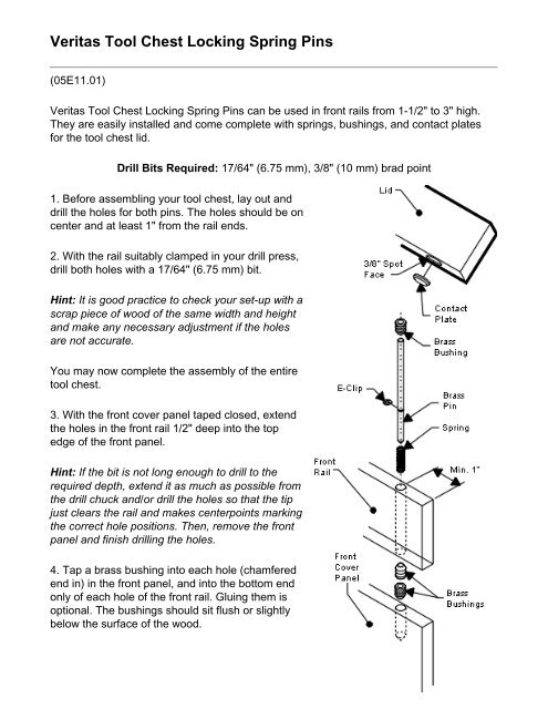
<strong>Veritas</strong> <strong>Tool</strong> <strong>Chest</strong> <strong>Locking</strong> <strong>Spring</strong> <strong>Pins</strong><br />
(05E11.01)<br />
<strong>Veritas</strong> <strong>Tool</strong> <strong>Chest</strong> <strong>Locking</strong> <strong>Spring</strong> <strong>Pins</strong> can be used in front rails from 1-1/2" to 3" high.<br />
They are easily installed and come complete with springs, bushings, and contact plates<br />
for the tool chest lid.<br />
Drill Bits Required: 17/64" (6.75 mm), 3/8" (10 mm) brad point<br />
1. Before assembling your tool chest, lay out and<br />
drill the holes for both pins. The holes should be on<br />
center and at least 1" from the rail ends.<br />
2. With the rail suitably clamped in your drill press,<br />
drill both holes with a 17/64" (6.75 mm) bit.<br />
Hint: It is good practice to check your set-up with a<br />
scrap piece of wood of the same width and height<br />
and make any necessary adjustment if the holes<br />
are not accurate.<br />
You may now complete the assembly of the entire<br />
tool chest.<br />
3. With the front cover panel taped closed, extend<br />
the holes in the front rail 1/2" deep into the top<br />
edge of the front panel.<br />
Hint: If the bit is not long enough to drill to the<br />
required depth, extend it as much as possible from<br />
the drill chuck and/or drill the holes so that the tip<br />
just clears the rail and makes centerpoints marking<br />
the correct hole positions. Then, remove the front<br />
panel and finish drilling the holes.<br />
4. Tap a brass bushing into each hole (chamfered<br />
end in) in the front panel, and into the bottom end<br />
only of each hole of the front rail. Gluing them is<br />
optional. The bushings should sit flush or slightly<br />
below the surface of the wood.
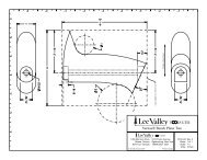
5. The locking pins fit a 3" tall front rail. If your front rail is less than this, the top<br />
(non-spherical) ends must be cut to the height of your front rail + 5/16" (see sizing chart).<br />
6. Install the E-clip into the groove on each pin. As shown in the illustration, place each<br />
pin and spring into the holes in the front rail and check that they mate with the front cover<br />
panel bushings when pushed down. If needed, the angle of the bushings can be adjusted<br />
by prying them sideways with a small screwdriver. Slide a bushing (chamfered end down)<br />
onto each exposed pin. Tap each bushing in until flush with the top of rail.<br />
Important: If you ever need to remove the locking<br />
pins, it is advisable not to use glue for the upper<br />
bushings. Without glue, the top bushings can be<br />
pressed out by lightly tapping the pins up, from<br />
the bottom side of the front rail, using a 1/8" to<br />
5/32" pin punch (or equivalent). Supporting the<br />
top edge of the rail with a scrap piece of wood<br />
that has a 9/32" hole in it will prevent splintering.<br />
7. With the front panel open, close the lid and lightly<br />
tap each pin from the underside to mark the contact<br />
plate locations. Using a 3/8" brad point bit, drill a<br />
Sizing Chart<br />
Rail Height + 5/16" = Pin Length<br />
Rail Height Pin Length<br />
2-3/4" 3-1/16"<br />
2-1/2" 2-13/16"<br />
2-1/4" 2-9/16"<br />
2" 2-5/16"<br />
1-3/4" 2-1/16"<br />
1-1/2" 1-13/16"<br />
spot face 1/16" deep. Place the contact plate in the hole to check that it sits flush with the<br />
wood. If not, spot the hole slightly deeper and check again. Once the plates sit flush, glue<br />
them in place.