PROBO PR70 PR70-DL PR120 PR120-DL - Automatizari pentru porti
PROBO PR70 PR70-DL PR120 PR120-DL - Automatizari pentru porti
PROBO PR70 PR70-DL PR120 PR120-DL - Automatizari pentru porti

You also want an ePaper? Increase the reach of your titles
YUMPU automatically turns print PDFs into web optimized ePapers that Google loves.
<strong>PROBO</strong> <strong>PR70</strong><br />
<strong>PR70</strong>-<strong>DL</strong><br />
<strong>PR120</strong> <strong>PR120</strong>-<strong>DL</strong><br />
MOTORIDUTTORE ELETTROMECCANICO IRREVERSIBILE PER PORTE SEZIONALI E BASCULANTI<br />
ISTRUZIONI E AVVERTENZE PER L’INSTALLAZIONE, L’USO E LA MANUTENZIONE.<br />
IRREVERSIBLE ELECTRO-MECHANICAL OPERATOR FOR SECTIONAL AND UP-AND-OVER DOORS<br />
INSTRUCTIONS AND INDICATIONS FOR INSTALLATION, USE AND MAINTENANCE.<br />
MOTO-REDUCTEUR ELECTROMECANIQUE IRREVERSIBILE POUR PORTES SECTIONNELLES ET BASCULANTES<br />
INSTRUCTIONS ET CONSEILS POUR L’INSTALLATION, L’EMPLOI ET L’ENTRETIEN.<br />
MOTORREDUCTOR ELECTROMECÁNICO IRREVERSIBLE PARA PUERTAS SECCIONALES Y BASCULANTES<br />
INSTRUCCIONES Y ADVERTENCIAS PARA LA INSTALACIÓN, EL USO Y EL MANTENIMIENTO.<br />
CENTRAIS DE COMANDO PARA PORTÕES DE BATENTE<br />
INSTRUÇÕES E ADVERTÊNCIAS PARA A INSTALAÇÃO, USO E MANUTENÇÃO.<br />
ELEKTROMECHANISCHER TORANTRIEB <strong>PROBO</strong> FÜR SCHWING- UND GARAGENTORE<br />
ANLEITUNGEN UND HINWEISE FÜR INSTALLATION, GEBRAUCH UND WARTUNG.<br />
MOTOREDUKTOR ELEKTROMECHANICZNY NIEZWROTNY DO BRAM SEKCYJNYCH I WAHADŁOWYCH<br />
INSTRUKCJE I WSKAZÓWKI DOTYCZĄCE MONTAŻU, UŻYTKOWANIA I KONSERWACJI.<br />
НЕРЕВЕРСИВНЫЙ ЭЛЕКТРОМЕХАНИЧЕСКИЙ ПОТОЛОЧНЫЙ ПРИВОД ДЛЯ СЕКЦИОННЫХ И<br />
ПОДЪЕМНО-ПОВОРОТНЫХ ВОРОТ<br />
ИНСТРУКЦИИ, ЗАМЕЧАНИЯ ПО МОНТАЖУ, ЭКСПЛУАТАЦИИ И ТЕХНИЧЕСКОМУ ОБСЛУЖИВАНИЮ.<br />
ELEKTROMECHANICKÝ NEREVERZNÝ POHON <strong>PROBO</strong> PRE SEKČNÉ A VÝKLOPNÉ GARÁŽOVÉ BRÁNY<br />
UPOZORNENIA A NÁVOD NA INŠTALÁCIU, POUŽÍVANIE A ÚDRŽBU.<br />
VEZÉRLŐEGYSÉG 24 V-OS MOTOROKHOZ<br />
SZERELÉSI UTASÍTÁSOK ÉS FIGYELMEZTETÉSEK, HASZNÁLAT ÉS KARBANTARTÁS.<br />
ŘÍDÍCÍ JEDNOTKA POHONU PRO AUTOMATIZACI VYBAVENOU 24 V MOTORY<br />
POKYNY A VAROVÁNÍ PRO INSTALACI, POUŽITÍ A ÚDRŽBU.<br />
LC020508 - LIFE - 10/2008
ACER<br />
INSTALLAZIONE STANDARD<br />
STANDARD INSTALLATION<br />
INSTALLATION STANDARD<br />
INSTALACIÓN ESTÁNDAR<br />
INSTALAÇÃO STANDARD<br />
STANDARDINSTALLATION<br />
INSTALACJA STANDARDOWA<br />
СТАНДАРТНАЯ УСТАНОВКА<br />
ŠTANDARTNÁ INŠTALÁCIA<br />
ÁLTALÁNOS TELEPÍTÉS<br />
STANDARTNÍ INSTALACE<br />
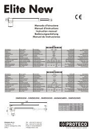
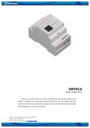
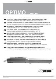
Tab.1: componenti e dispositivi di un’automazione tipo, vedi figura.<br />
Тав.1: Компоненты и устройство автоматики типа, см. рис.<br />
Tab.2: componenti e dispositivi di un’automazione tipo, vedi figura.<br />
Тав.1: Компоненты и устройство автоматики типа,<br />
см. рис.<br />
<strong>PROBO</strong><br />
ACER<br />
Manuale di istruzioni<br />
Manuale di istruzioni<br />
1 A
DESCRIZIONE PARTICOLARI<br />
SPECIFIC DESCRIPTION<br />
DESCRIPTION SPECIFIQUE<br />
DESCRIPCIONES PARTICULARES<br />
DESCRIÇÕES PRELIMINARES<br />
OPIS ELEMENTÓW<br />
4<br />
BESCHREIBUNG DERBESTANDTEILEN<br />
ОПИСАНИЕ ОСОБЕННОСТЕЙ<br />
ŠTANDARTNÁ INŠTALÁCIA<br />
ÁLTALÁNOS TELEPÍTÉS<br />
STANDARTNÍ INSTALACE<br />
16 17<br />
7<br />
6<br />
2<br />
1<br />
8 9<br />
10 11<br />
5<br />
14<br />
1<br />
13 15<br />
12<br />
3<br />
2 A
MANUAL DESTINED TO PROFESSIONAL FITTERS ONLY<br />
Under applicable law, installation may only be performed by professional fitters.<br />
1 TECHNICAL DATA<br />
LIFE home integration reserves the right to vary technical features at any time and without giving prior notice, whilst maintaining the same intended usage and functions.<br />
<strong>PROBO</strong> is a family of irreversible electromechanical operators for the automation of residential type sectional and up-and-over doors. The range is<br />
constituted by two different power models. <strong>PR70</strong>-07 / <strong>PR70</strong>-<strong>DL</strong> e <strong>PR120</strong>-07 / PR12 <strong>DL</strong>. Motion transmission is performed through chain or belt-driven<br />
retainer runners; the retainer runner is equipped with a release mechanism in order to make it possible to move the door manually in the event of need.<br />
<strong>PROBO</strong><br />
Irreversible electro-mechanical operator for sectional and up-and-over door with<br />
built in encoder and electronic unit.<br />
Mains power supply<br />
Motor power supply<br />
Max. power<br />
Max. input<br />
Input power to line (230V)<br />
Thrust<br />
Lubrication<br />
Electromechanical end stops<br />
Encoder<br />
Speed<br />
Work cycles<br />
Nominal work time<br />
Courtesy light 24 Vdc (internal)<br />
Operating temp.<br />
Protection class<br />
Motor insulation class<br />
Assembly<br />
Dimensions / weight<br />
Use in acid, saline or potentially explosive environment<br />
Max. leaf surface area*<br />
Control unit<br />
V<br />
V<br />
W<br />
A<br />
A<br />
N<br />
Type<br />
m/s<br />
%<br />
min<br />
W (max.)<br />
°C<br />
IP<br />
<strong>PR70</strong>-07 / PR 70-<strong>DL</strong><br />
260<br />
8,5<br />
1,2<br />
650<br />
0,10 - 0,18<br />
MODELS<br />
230 Vac 50 Hz<br />
24 V dc<br />
grease<br />
no<br />
yes<br />
50<br />
13<br />
15<br />
from -20 to +70<br />
20<br />
F<br />
Horizontal ceiling-mounted on dedicated runner<br />
442x213x142 (h) mm / 6.7 Kg<br />
no<br />
11.5<br />
RG1 24P / RG1 24 <strong>DL</strong><br />
<strong>PR120</strong>-07 / PR 120-<strong>DL</strong><br />
310<br />
10<br />
1,3<br />
1100<br />
0,08 - 0,12<br />
18<br />
RG1 24P / RG1 24 <strong>DL</strong><br />
ENGLISH<br />
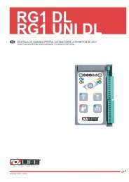
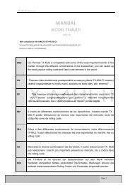
Fig.1<br />
2 INSTALLATION<br />
2.1 Preliminary checks and usage restrictions<br />
442<br />
143 213<br />
Before commencing installation, the following preliminary checks must be performed:<br />
a) The area in which the automation is installed must provide adequate space for performing maintenance and manual release operations. Check the<br />
total dimensions by referring to fig. 1, and the manuale provided.<br />
b) The automation may be installed on both sectional and up-and-over doors; for up-and-over doors it is necessary to use the oscillating, curved arm APRB<br />
The value given in Tab. is intended as a rough guide as many factors dictate the limits of use and they must be considered carefully for each installation.<br />
<strong>PR70</strong>-07 / <strong>PR70</strong>-<strong>DL</strong><br />
<strong>PR120</strong>-07 / <strong>PR120</strong>-<strong>DL</strong><br />
Maximum door width (m)* 5<br />
6.5<br />
The maximum height of the door to be automated<br />
depends on the length of the runner used, which is<br />
provided separately from the operator.<br />
* Values reported to gates perfectly balanced.<br />
1
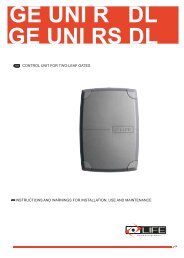
2.2 Installing operator components<br />
2.2.1 Mounting the operator on the runner<br />
a) Open the operator hatch (1) and loosen the clamping screws (2).<br />
b) Then remove the cap (3) from the base, paying attention to the rear fitting of the<br />
cover (4) with the base.<br />
c) Remove the omega-shaped support brackets (5) by unscrewing the 4 screws (6)<br />
that fasten them to the base (7).<br />
d) Mount the operator on the runner, introducing the protruding shaft of the operator (8)<br />
into the hole on the block (9), taking care not to force the tab.<br />
e) Fasten the operator to the runner using the omega-shaped support brackets (5), fastening<br />
it with the four hexagonal-headed screws (6) provided with the operator base (7).<br />
3<br />
6<br />
1<br />
2<br />
4<br />
7<br />
8<br />
9<br />
5<br />
5<br />
7<br />
6<br />
2.2.2 Automation installation<br />
ATTENTION: the automation may only be installed once the various parts of the runner have been installed and the operator has been installed on the runner.<br />
Sectional door:<br />
a) The minimum vertical distance of the sectional door from the ceiling A is 40 mm. If the distance exceeds the height of the brackets adequate spacers<br />
must be used.<br />
b) The vertical distance of the sectional door from the operator runner B must be between 10 and 65 mm.<br />
c) Close the door and measure out the centre point, marking it on the door and on the wall/ceiling.<br />
d) At a distance of 73 mm to the left and right of the centre, mark the centre of the fixing holes of the front runner brackets, then drill the holes and insert<br />
the screw anchors.<br />
B<br />
10 : 100 mm<br />
40 mm<br />
A<br />
73mm<br />
73mm<br />
2
e) Lift the front part of the runner leaving the operator resting on the floor and firmly fix the front brackets onto the screw anchors arranged previously<br />
using suitable screws and washers.<br />
f) Completely lift the runner with the operator and position it ensuring that it is parallel to the ceiling.<br />
g) Adjust the position of the rear brackets (8) so that they rest well on the ceiling, then mark the centres for the fixing holes.<br />
h) Drill the holes, insert the screw anchors and firmly fasten the two rear brackets (8) to the ceiling using suitable screws and washers.<br />
i) Ensure that the runner is perfectly aligned and level; if necessary adjust the position in relation to the rear brackets.<br />
j) Lock all the front and rear bracket clamping screws.<br />
ENGLISH<br />
8<br />
k) Release the drive trolley (9) by pulling the cord and take it forward to allow the installation<br />
of the drive bracket (10) on the sectional door.<br />
l) Position the drive bracket (10) on the upper edge of the sectional door and fasten using<br />
suitable screws or rivets.<br />
m) Connect the drive bracket (10) to the thrust arm (11) using the screws and self-locking<br />
nut provided.<br />
ATTENTION: in order for the mechanism to work properly the angle between the runner (12)<br />
and the thrust arm (10) must not be greater than 30°.<br />
n) Release the operator and manually perform a number of opening and closure manoeuvres<br />
in order to verify that it is correctly balanced: the manoeuvres must be performed with ease<br />
and the door must move without catching or swinging.<br />
Up and over door:<br />
The APRB curved oscillating arm is required, refer to the instruction manual provided.<br />
10<br />
0<br />
11<br />
3
2.2.3 Operator release<br />
ATTENTION:<br />
• The fitter must permanently fix the label describing the manual release operation close to the manual release lever.<br />
• The activation of the manual release could cause an uncontrolled movement of the door in the event of mechanical damage or unbalanced conditions.<br />
• Before performing the manoeuvre switch off the electricity supply to the automation.<br />
This command is used in the event of a blackout or system faults, to release the operator transmission and allow manual moving of the sectional/upand-over<br />
door.<br />
a) Pull the cord connected to the mobile trolley (1) and move the door manually.<br />
b) The door is now free and can be moved by hand.<br />
c) To reconnect the transmission take the door to the initial position until it hooks back up.<br />
1<br />
ATTENTION: for garages that do not have a second access, the ASEC PR device for manual release from outside must be installed<br />
3 WIRING AND CONNECTIONS<br />
• The operator may only be connected to a suitable control unit manufactured by Life.<br />
• All wiring and connection operations must be carried out with the operator disconnected from the electricity supply; if the disconnection device is not<br />
n view, display a sign reading “ATTENTION: MAINTENANCE WORK IN PROGRESS”.<br />
The internal operator wiring performed by the Manufacturer, may not be modified under any circumstances.<br />
This manual does not describe how the electrics system should be prepared for connection to the mains however it gives the following warnings:<br />
• The electricity power line must be installed and connected by a qualified technician or professional fitter.<br />
• The electricity supply line must have adequate protection against short circuits and must be earthed.<br />
• The power supply network must contain a unipolar disconnection device with an opening distance of the contacts equal or greater than<br />
3.5 mm that assures the complete disconnection of the power supply.<br />
3.1 Introducing the electric wires into the operator<br />
a) To access the terminals in the control unit, remove the cap (1) that covers the operator.<br />
b) Open the operator hatch (2) and loosen the clamping screws (3).<br />
c) Then remove the cap (1) from the base, paying attention to the rear fitting of the cover (4) with the base.<br />
d) Loosen the screws (5) that fastens the cable gland (6) to the base and remove it.<br />
e) The cables must be inserted through the corresponding holes on the base (7): keep the 230V cables separate from the very low voltage ones.<br />
f) Leave the cables about 40cm longer.<br />
g) Fasten the cables to the base using the assembly of the cable gland (6).<br />
For connection to a 230 V ac 50 Hz power supply, use the power cable with ready-wired schuko plug provided with the operator only (8).<br />
Do not modify the connections between the power cable (7), transformer (8) and control unit (9).<br />
The power cable provided may not be extended or shortened.<br />
7<br />
6<br />
5<br />
1<br />
4<br />
2<br />
3<br />
Cable length<br />
max 40 mm<br />
8<br />
9<br />
10<br />
4
Declaration of conformity<br />
under Directive 98/37/EC, appendix II, part B (Manufacturer’s Declaration of CE Conformity)<br />
LIFE Home Integration<br />
Via 1 Maggio, 37<br />
31043 FONTANELLE (TV) – Italy<br />
ENGLISH<br />
declares that the following product:<br />
<strong>PROBO</strong> <strong>PR70</strong> <strong>PR70</strong>-<strong>DL</strong> <strong>PR120</strong> <strong>PR120</strong>-<strong>DL</strong><br />
satisfies the essential requisites established in the following directives:<br />
• Low voltage directive 73/23/EEC and subsequent amendments,<br />
• Electromagnetic compatibility directive 89/336/EEC and subsequent amendments,<br />
• Radio and telecommunications equipment directive 1999/5/EC and subsequent amendments.<br />
and satisfies the following standards:<br />
• EN 12445:2000 Industrial, commercial and garage doors and gates – Safety in the usage of motorised doors –<br />
testing methods<br />
• EN 12453: Industrial, commercial and garage doors and gates – Safety in the usage of motorised doors –<br />
Requisites<br />
• EN 60204-1:1997 Machinery safety – Electric equipment of the machine – Part 1: general rules.<br />
The Manufacturer also declares that it is not permitted for the abovementioned components to be used until such time as the<br />
system in which they are incorporated is declared conform to directive 98/37/EC.<br />
Fontanelle 20/10/2007 Name of Signor: Faustino Lucchetta<br />
Position:<br />
Signature:<br />
Managing Director<br />
__________________<br />
5
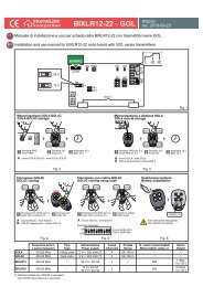
1 5RI15800 2 5RI11100<br />
3 5RI11200 4 5RI11300<br />
5 5RI11400 6 5RI20000 7 5RI11500<br />
8 5RI18500 <strong>PR70</strong> 9 5RI18600 <strong>PR120</strong><br />
10 5RI28400 <strong>PR70</strong> <strong>DL</strong> 11 5RI28500 <strong>PR120</strong> <strong>DL</strong><br />
14 5RI01900<br />
12 5RI01900 13 1AH00900 <strong>PR70</strong>-<strong>PR120</strong> 16 5RI11600 <strong>PR70</strong><br />
17 5RI38300 <strong>PR70</strong> <strong>DL</strong>-<strong>PR120</strong> <strong>DL</strong> 17 5RI11700 <strong>PR120</strong><br />
3 A