Insulated Wall Cladding - NRG
Insulated Wall Cladding - NRG
Insulated Wall Cladding - NRG

You also want an ePaper? Increase the reach of your titles
YUMPU automatically turns print PDFs into web optimized ePapers that Google loves.
CAVITYRELEASE<br />
BAL29<br />
(AS1530.8.1-2007)<br />
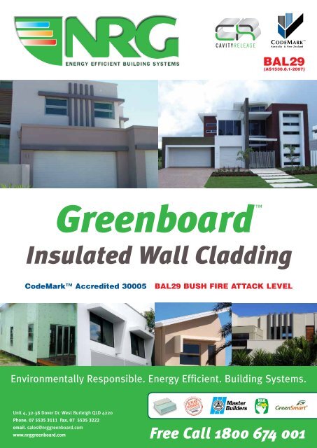
Greenboard<br />
<br />
<strong>Insulated</strong> <strong>Wall</strong> <strong>Cladding</strong><br />
CodeMark Accredited 30005 BAL29 BUSH FIRE ATTACK LEVEL<br />
Environmentally Responsible. Energy Efficient. Building Systems.<br />
Unit 4, 32-38 Dover Dr. West Burleigh QLD 4220<br />
Phone. 07 5535 3111 Fax. 07 5535 3222<br />
email. sales@nrggreenboard.com<br />
www.nrggreenboard.com<br />
Free Call 1800 674 001
<strong>NRG</strong> GREENBOARD and the ENVIRONMENT<br />
• <strong>NRG</strong> Greenboard Energy Efficient Insulative <strong>Wall</strong>ing System Product Information.<br />
• <strong>NRG</strong> Greenboard is comprised of 98% air and therefore only 2% polystyrene making it a highly<br />
efficient use of raw material.<br />
• <strong>NRG</strong> Greenboard remains inert, is non toxic, odour free and nonbiodegradable.<br />
• No CFC’s or HCFC’s foam agents are used in its manufacture, so <strong>NRG</strong> Greenboard causes no damage<br />
to the ozone layer.<br />
• Effective installation of <strong>NRG</strong> Greenboard can cut carbon dioxide emissions by up to 50%.<br />
• The R-value of <strong>NRG</strong> Greenboard does not deteriorate during its life time; therefore the reduction in<br />
emissions lasts the full lifetime of the building.<br />
• The energy used to manufacture <strong>NRG</strong> Greenboard is recovered within six months by the energy<br />
saved in the building in which <strong>NRG</strong> Greenboard is installed.<br />
• Typically, for every kg of oil used in <strong>NRG</strong> Greenboard manufacturing, about 200kg will be saved in<br />
reduced heating demands.<br />
• All <strong>NRG</strong> Greenboard waste is recycled. Either through installation of off-cuts in the wall cavity or it<br />
can be granulated and mixed with virgin material to make new products.
CodeMark Certificate<br />
Changes to the 2010 version of Building Code of Australia<br />
are that all building products must comply with the BCA.<br />
CodeMark certified products comply with the BCA.<br />
<strong>NRG</strong> Greenboard has achieved CodeMark Certification.<br />
Each state has regulations, ensuring that a CodeMark<br />
building solution can not be rejected.<br />
For their own protection, local authorities (certifiers, councils,<br />
surveyor, designers, home insurance companies) are insisting<br />
on CodeMark Certification.<br />
<strong>NRG</strong> Specification May 2010 | 6th EDITION 1
TABLE OF CONTENTS<br />
Greenboard <strong>Insulated</strong> <strong>Wall</strong> <strong>Cladding</strong> 3<br />
Greenboard Product Data 4<br />
<strong>NRG</strong> Greenboard Insulative <strong>Wall</strong>ing System 4<br />
Properties and Advantages of the <strong>NRG</strong> Greenboard <strong>Wall</strong>ing System 4<br />
Design Information General 6<br />
<strong>NRG</strong> Greenboard Installation Procedure 8<br />
<strong>NRG</strong> Greenboard Bead and Sealant Procedure 11<br />
<strong>NRG</strong> Greenboard Texture Coating System: - Procedure 12<br />
Applied Finish Specification 13<br />
<strong>NRG</strong> Accessories 15<br />
<strong>NRG</strong> Check List 29<br />
<strong>NRG</strong> Warranty 30<br />
Thermal Rating for Greenboard <strong>Wall</strong> System 32<br />
2<br />
<strong>NRG</strong> Specification May 2010 | 6th EDITION
GREENBOARD<br />
<strong>Insulated</strong> wall cladding<br />
Greenboard is an <strong>Insulated</strong> <strong>Wall</strong> Panel that combines<br />
exterior cladding with insulation so designers can achieve<br />
the 6 star energy ratings that have been introduced into the<br />
building code. Greenboard‘s insulated core of high quality<br />
expanded polystyrene puts the Greenboard insulated panel<br />
in the best place of the building, as far towards the outer side<br />
as possible.<br />
Greenboard <strong>Insulated</strong> <strong>Wall</strong> Panel is a lightweight, energy<br />
efficient product and once coated the system provides a<br />
weather resistant, seam free rendered finish.<br />
Greenboard Advantages<br />
CodeMark Certification<br />
All building products must comply with the BCA (Building Code<br />
of Australia). <strong>NRG</strong> Building Systems has achieved CodeMark on<br />
Greenboard <strong>Insulated</strong> <strong>Wall</strong> <strong>Cladding</strong> meaning Greenboard<br />
complies to the BCA.<br />
Insulation Qualities<br />
All insulation materials are rated for their performance in<br />
restricting heat transfer. This rating is expressed as an<br />
R-value which is a measure of the material’s resistance to<br />
heat transfer (thermal resistance). The higher the R-value the<br />
greater insulating effect.<br />
Total <strong>Wall</strong> R-value for using Greenboard<br />
Thickness (mm)<br />
50mm 60mm 75mm 100mm<br />
R-value on total wall<br />
2.18 R 2.44 R 2.83 R 3.48 R<br />
Sound Rating<br />
<strong>NRG</strong> Building Systems has tested 60mm Greenboard<br />
total wall system and the acoustic performance result was<br />
Rw35,Ctr-6. Please refer to <strong>NRG</strong> test results. The Greenboard<br />
walling system can be further enhanced by using a “sound<br />
rated” insulation batt. Please refer to insulation manufacture’s<br />
specifications.<br />
Grooved Panel<br />
The surface of the Greenboard panel is Grooved both<br />
sides allowing the inside surface to breathe and channel any<br />
possible condensation away through the Grooves, downwards<br />
to the base of the wall. This is particularly important where<br />
“insulation” or “breather sarking” is used. The additional<br />
advantage being that when the<br />
Grooved face of Greenboard is rendered the system<br />
becomes stronger as the render gets into the Groove to form<br />
a core shape for better adhesion and a stronger more rigid<br />
Greenboard system.<br />
Easy to Use<br />
Greenboard‘s lightweight panel size is 2500 x 1200 allowing<br />
installers to cover the external walls quicker and easier. For the<br />
builder and their client, Greenboard gets the project to lock<br />
up stage quicker allowing other trades to start and complete<br />
their tasks.<br />
Environmentally Friendly<br />
Greenboard requires less energy to produce than other<br />
traditional building materials and contains no CFC’s nor HCFC’s.<br />
Greenboard does not contain ozone depleting substances<br />
and none are used in the manufacturing of this product.<br />
Greenboard can be recycled or <strong>NRG</strong> recommends left over<br />
Greenboard can be placed in the walls as extra insulation.<br />
Termite Retardant<br />
Greenboard contains a termite retardant (Bifenthrin)<br />
and <strong>NRG</strong> uses 62% more in their product than the<br />
minimum required.<br />
Render Levels of Finish<br />
Reinforced render is applied to the Greenboard substrate<br />
at approximately 4-8mm in thickness which allows qualified<br />
applicators to screed out usual imperfections and form a seam<br />
free level 5 finish. <strong>NRG</strong> recommends render over Greenboard<br />
should be specified by a coating manufacturer.<br />
Fire Retardant<br />
Greenboard contains a flame retardant additive and will not<br />
support fire, it has a spread of flame index of zero. If in a fire<br />
situation the toxic fumes are no greater than that of timber and<br />
other building materials.<br />
<strong>NRG</strong> Specification May 2010 | 6th EDITION 3
Greenboard Product Data<br />
Greenboard Energy Efficient Insulative <strong>Wall</strong>ing System Product Information.<br />
<strong>NRG</strong> Greenboard is an insulative walling system suitable for external cladding of timber or steel framed buildings as well as solid<br />
concrete and masonry walls. The system provides a weather resistant, seam free rendered finish in a wide range of textures and<br />
colours. It also provides continuous thermal insulation over the entire wall. Developed in Germany in 1973, these systems have been<br />
extensively used throughout Western Europe and North America where strict environmental laws are in place governing the energy<br />
efficiency of both private and commercial buildings. The system is now well established in Australia ranging from dry arid areas, to<br />
tropical and alpine regions, whilst proving energy efficiency, cost effective and flexible construction alternative. The <strong>NRG</strong> Company is<br />
providing and increasing research and development of the system to improve the product.<br />
<strong>NRG</strong> Greenboard Insulative <strong>Wall</strong>ing<br />
System consists of:<br />
14.1.1 An enhanced expanded polystyrene (EPS) insulation<br />
board impregnated with an insect repellent compound<br />
and flame retardant. The board is mechanically fixed<br />
to timber/steel stud framing or reinforced concrete<br />
or masonry wall. The surface of the Greenboard<br />
panel is grooved both sides allowing the inside<br />
surface to breath and channel any possible<br />
condensation away through the grooves, downwards<br />
to the base of the wall. This is particularly important<br />
where 'insulation' or 'breather sarking' (refer 16.1.9) is<br />
used. The additional advantage being that the grooved<br />
'face' surface of the Greenboard panel provides an<br />
excellent 'key' to accept the reinforced render system.<br />
14.1.2 <strong>NRG</strong> Greenboard Washers and Screws (Class 3) are<br />
used for fixing to timber or steel framing, while special<br />
anchors are used for fixing to masonry wall surfaces.<br />
14.1.3 External PVC (UV Stabilised) angle beads and<br />
window trims.<br />
14.1.4 A polymer modified cement render reinforced with an<br />
alkali resistant fiberglass mesh.<br />
14.1.5 Acrylic texture coating and or pigmented membrane<br />
finished in your selected colour.<br />
14.1.6 The <strong>NRG</strong> <strong>Wall</strong>ing System incorporating reinforced<br />
renders and textured finish coatings form a complete<br />
cladding system from the frame to the finished<br />
surface.<br />
14.1.7 Vermin Retardant.<br />
14.1.9 <strong>NRG</strong> Greenboard Insulative <strong>Wall</strong>ing System: Sound<br />
insulation value - 60mm Greenboard Refer (16.1.5 -<br />
Acoustic Values (Table D) = Rw 35, Ctrr -6<br />
14.1.10 <strong>NRG</strong> Greenboard Insulative <strong>Wall</strong>ing System: is an<br />
extremely high-energy, efficient product reducing<br />
heating costs in winter and cooling costs in summer.<br />
14.1.11 <strong>NRG</strong> Greenboard Insulative <strong>Wall</strong>ing Systems unique<br />
grooved surface provides strength and flexibility of<br />
finish, allowing a vast range of architectural designs,<br />
finishes and colours to complement any surroundings.<br />
14.1.12 <strong>NRG</strong> Greenboard Insulative <strong>Wall</strong>ing Systems is<br />
the ideal substrate for lightweight construction, 2nd<br />
storey additions, reactive soil and mine subsidence<br />
areas are concerned.<br />
Properties and Advantages of the<br />
<strong>NRG</strong> Greenboard <strong>Wall</strong>ing System<br />
<strong>NRG</strong> Greenboard panel is manufactured from high density,<br />
rigid, expanded polystyrene. The raw material is gained as a<br />
by-product of the manufacture of oil.<br />
Greenboard is manufactured without the use of CFC’s and<br />
does not contain or emit any poisonous gas. In fact, <strong>NRG</strong><br />
Greenboard is made up of 98% air entrapped in a closed<br />
cellular structure of polystyrene. This entrapped air accounts<br />
for the extremely good insulation properties<br />
of the Greenboard.<br />
The off cuts of <strong>NRG</strong> Greenboard can be glued within the<br />
wall cavity prior to the installation of the internal linings<br />
as additional insulation. This cuts down on the impact to<br />
our environment as all the material is being used, leaving a<br />
minimal amount of material to be removed from site.<br />
14.1.8 A high impact strength finish.<br />
4<br />
<strong>NRG</strong> Specification May 2010 | 6th EDITION
• 98% ENTRAPPED AIR<br />
• SUPPORTING THE ENVIRONMENT<br />
• NO CFC’S USED IN THE MANUFACTURING PROCESS<br />
• NO SITE WASTAGE - USING ALL OFF-CUTS AS<br />
ADDED INSULATION<br />
• SUPPORTING THE CONSUMER BY REDUCING<br />
HOME AND BUSINESS<br />
• GREENBOARD RENDER, REINFORCED WITH 150G/m 2<br />
FIBERGLASS MESH FOR HIGH IMPACT STRENGTH.<br />
• ADDED FIRE RETARDANT WILL NOT<br />
SUPPORT COMBUSTION<br />
• DESIGN FLEXIBILITY.<br />
• FULL RANGE OF COLOURED FINISHES AND STYLES<br />
• EXCEPTIONAL THERMAL QUALITIES<br />
• acoustic values<br />
• VERMIN RETARDENT<br />
<strong>NRG</strong> Specification May 2010 | 6th EDITION 5
15.1.1 Insulation for Energy Efficient Buildings<br />
The Greenboard system is the most cost efficient<br />
method of insulation in terms of R-value per dollar.<br />
Unlike some other methods of insulation that allow<br />
thermal bridging across the timber or steel studs<br />
framing. <strong>NRG</strong> Greenboard provides a continuous<br />
insulative sheath around the entire building.<br />
15.1.2 Warranty - 10yr<br />
i. <strong>NRG</strong> warrants that the Greenboard sheets<br />
(the "Product") will be free from defects due to<br />
defective factory workmanship or materials prior<br />
to the installation of the Product for a period<br />
of 10 years from the date of purchase, subject to<br />
compliance with the conditions published in <strong>NRG</strong><br />
Product Warranty 2007 - Free Call 1800 674 001<br />
www.nrggreenboard.com<br />
15.1.3 Easy to Render<br />
The surface of the <strong>NRG</strong> Greenboard is grooved<br />
providing an excellent substrate for<br />
Reinforced Render Systems.<br />
15.1.4 Energy Efficient Production<br />
Greenboard uses much less energy in its production<br />
than conventional building materials such as concrete<br />
and masonry.<br />
15.1.5 Fashionable Render Finishes<br />
Available in a wide range of Architectural colours and<br />
styles (Refer to your selected manufacturers, texture<br />
coating specifications).<br />
15.1.6 Design Freedom<br />
Curved walls, rounded corners, embossed patterns,<br />
raised wall areas, mouldings and other architectural<br />
features are simple to achieve and cost-effectively with<br />
the versatile <strong>NRG</strong> <strong>Wall</strong>ing System.<br />
15.1.7 Vermin Retardant<br />
<strong>NRG</strong> Greenboard is impregnated with a natural<br />
insect retardant, (Bithentrin)<br />
15.1.8 Biologically Inert<br />
The board will not rot and provides no nutritive value<br />
for insects or micro-organisms.<br />
Design Information General<br />
The <strong>NRG</strong> Greenboard Insulative <strong>Wall</strong>ing System forms a<br />
continuous weather-resistant thermal envelope around the<br />
external walls of the building. The versatility of the building<br />
and the workable nature of the Greenboard composite<br />
panel permits greater design freedom. This system allows the<br />
designer to economically provide a fashionable, long lasting<br />
render finish as well as comply with the strictest energy ratings<br />
required in modern building codes.<br />
Tests show that a properly insulated building can reduce<br />
energy costs by up to 75%. This greatly reduces the running<br />
costs of the building in terms of energy savings and reduces<br />
the amount of green house gases released into the atmosphere<br />
16.1.1 Structure<br />
<strong>NRG</strong> Greenboard 50mm, 60mm, 75mm and 100mm<br />
thick has sufficient strength and rigidity to be<br />
supported by wall framing spaced at 450mm maximum<br />
centres. <strong>NRG</strong> Greenboard can be installed over<br />
masonry walls to increase the "R–value" of the<br />
masonry wall system or brick veneer construction.<br />
16.1.2 Building - Wind Zones (Table A)<br />
When mechanically fixed to a variety of substrates in<br />
accordance with the "<strong>NRG</strong> Greenboard <strong>Wall</strong>ing<br />
System – Installation Manual for use in the<br />
following categories.<br />
Wind Description Design<br />
Region<br />
Wind<br />
Velocity<br />
N2 Sheltered Suburban - Non Cyclonic 40<br />
N3 Exposed Suburban - Non Cyclonic 50<br />
C3 Exposed Suburban - Cyclonic 74<br />
C4 Exposed Suburban - Cyclonic 88<br />
16.1.3 Maximum Stud & Fastener Spacing’s (Table B)<br />
<strong>NRG</strong> Greenboard Maximum Stud & Fastener Spacing’s<br />
Suitable for <strong>NRG</strong> Greenboard Thicknesses of 40mm, 60mm, 75mm and 100mm<br />
Regions -<br />
Wind Category<br />
Cyclonic Non Cyclonic<br />
Stud<br />
Spacings<br />
(mm)<br />
Fastener<br />
Spacings<br />
(mm-Vertically)<br />
Number of<br />
Fasteners /m_<br />
N1 450 300 12<br />
N2 450 300 12<br />
N3 450 300 12<br />
N4 450 200 18<br />
N5 450 150 24<br />
C1 450 200 18<br />
C2 450 150 24<br />
C3 450 100 37<br />
Refer to AS1684:2010, AS4055:2006, NASH Standard: 2005. The framing substrate<br />
may be either cold-formed steel framing with a minimum 0.75mm BMT or Timber<br />
frame with JD4 minimum joint group.<br />
6<br />
<strong>NRG</strong> Specification May 2010 | 6th EDITION
16.1.4 Insulation Values (Table C)<br />
All insulation materials are rated for their performance<br />
In restricting heat transfer. This rating is expressed as<br />
An R-value which is the measure of material’s<br />
resistance To heat transfer (thermal resistance).<br />
The higher the R-value, the greater the<br />
insulating effect.<br />
Thickness 40 60 75 100<br />
Thermal conductivity at<br />
23oC (W/m2.k)<br />
R-value of insulation<br />
material<br />
0.037<br />
1.03 1.54 1.93 2.57<br />
Total R-value of<br />
wall from Rendered<br />
GreenboardTM<br />
Reflective sarking,<br />
cavity plasterboard 1.92R 2.44R 2.83R 3.48R<br />
16.1.7 Hazardous Building Materials<br />
When installation is complete the <strong>NRG</strong> Greenboard<br />
<strong>Wall</strong>ing System and the Greenboard Reinforced<br />
Render System is non-hazardous.<br />
16.1.8 External Moisture<br />
The "<strong>NRG</strong> Specifications & Installation Manual”<br />
contains specific details and instructions for flashing<br />
around windows, finishing to edges and sealing<br />
penetrations. Head, sill and jamb flashings must be<br />
used as specified. The <strong>NRG</strong> Greenboard <strong>Wall</strong>ing<br />
System must not be allowed to come into contact<br />
with the ground.<br />
16.1.9 Sarking<br />
<strong>NRG</strong> Building Systems highly recommends the use<br />
of vapor permeable sarking, equivalent to Sisalation®<br />
<strong>Wall</strong> Wrap (Breather) or similar, fixed directly behind<br />
the <strong>NRG</strong> Greenboard <strong>Wall</strong>ing System.<br />
16.1.5 Acoustic Values - <strong>NRG</strong> Greenboard (Table D)<br />
Summary of Acoustic Test Results: -<br />
60mm <strong>NRG</strong> Greenboard<br />
Acoustic<br />
Performance<br />
Side 1<br />
Framing<br />
Side 2<br />
6mm concrete render applied<br />
to 60mm thick expanded<br />
polystyrene foam.<br />
The polystyrene applied with<br />
sheet lengths vertical.<br />
90mm timber studs at 450mm<br />
centres 10mm Plasterboard<br />
applied with sheet lengths<br />
vertical. Edges caulked with<br />
expanding polyurethane foam.<br />
R w 35,C tr -6<br />
Ron Rumble Pty Ltd, Consulting Acoustical & Vibration Engineers - 28th August 2006<br />
The <strong>NRG</strong> Greenboard walling system can be further<br />
enhanced by using a ‘sound rated’ insulation batt (Refer to<br />
Insulation manufacturer’s specifications).<br />
16.1.6 Impact Resistance<br />
The Greenboard <strong>Wall</strong>ing System when installed<br />
in accordance with "<strong>NRG</strong> Specifications & Installation<br />
Manual" will have adequate resistance to impact loads<br />
likely to occur in normal residential and commercial<br />
use. The likelihood of damage in public areas in or<br />
around residential, commercial or industrial buildings<br />
where heavy impacts could occur should be considered<br />
at the design stage. Heavier grade fibreglass<br />
reinforcing mesh or multiple layers should be used and<br />
appropriate protection or barriers should be provided<br />
in vulnerable areas.<br />
<strong>NRG</strong> Specification May 2010 | 6th EDITION 7
16.1.10 Early Fire Hazard Properties (Table E)<br />
<strong>NRG</strong> Greenboard contains a flame retardant additive<br />
to inhibit accidental ignition from small flame source.<br />
Note:<br />
<strong>NRG</strong> Greenboard System must be separated<br />
from heat sources such as fireplaces, chimneys or<br />
flues. <strong>NRG</strong> Greenboard System Does not provide a<br />
fire rated wall.<br />
<strong>NRG</strong> Greenboard Index Rating<br />
Ignitability (0-20) 6<br />
Spread of Flame Index (0-10) 0<br />
Heat Evolved (0-10) 1<br />
Smoke Developed (0-10) 4<br />
<strong>NRG</strong> Greenboard Installation Procedure<br />
17.1.1 Installation Procedures <strong>NRG</strong> Greenboard<br />
<strong>Wall</strong>ing System<br />
This manual provides information on the correct<br />
procedures and materials to be used for the<br />
installation of <strong>NRG</strong> Greenboard <strong>Wall</strong>ing System<br />
over standard framed and solid structures. The<br />
drawings and details are provided to assist building<br />
designers in specifying the correct design and detail<br />
of the <strong>NRG</strong> <strong>Wall</strong>ing System. These details cover most<br />
common applications. If the details are to be altered<br />
or new ones proposed please contact <strong>NRG</strong> to discuss<br />
the changes. Failure to do so may void the<br />
systems warranty.<br />
These components that make up the <strong>NRG</strong> Greenboard<br />
Insulative <strong>Wall</strong>ing System are.<br />
• Screws and washers<br />
• Vapor permeable sarking<br />
• <strong>NRG</strong> Greenboard<br />
• PVC beads<br />
• Polymer modified render<br />
• Reinforced mesh<br />
• Texture top coat<br />
These components form part of the complete system<br />
and must not be substituted with other possible nonconforming<br />
materials.<br />
17.1.2 Timber and Steel Framing<br />
All timber and steel framing should conform to the<br />
relevant Australian Standards, as well as the local<br />
standards for structural requirements including wind<br />
loadings and bracing.<br />
<strong>NRG</strong> GreenboardTM is not a structural material and therefore<br />
should not be considered or used as a bracing material.<br />
person, to identify any deterioration or infestation<br />
by wood boring insects. Although <strong>NRG</strong> Greenboard<br />
is impregnated with an effective insect repellent, it will<br />
not arrest or prevent further infestations of the timber<br />
framing structure. Where necessary, repairs must be<br />
undertaken to ensure that the timber substrate is<br />
sound, straight and true.<br />
17.1-4 Back Blocking (Off Stud Joints)<br />
Where horizontal fixing of sheets ‘off stud’ join are to<br />
be made, it is necessary to back block as follows.<br />
i. By fixing an ‘off cut’ of stud material vertical,<br />
(widest face facing outwards) and securely<br />
nailing to bottom plate and noggin. Alternatively,<br />
between noggin and top plate, making sure to<br />
glue both Greenboard sheet edges with<br />
No-More Nails and fixing through each sheet into<br />
the ‘black block’ with washers and screws at<br />
maximum 300mm centre’s.<br />
ii. Alternatively, horizontal ‘back block’ using ‘off<br />
cuts’ can be placed at maximum 300mm centre’s,<br />
following the above procedure except that,<br />
with the two sheets in place, take ‘off cuts’,<br />
smear with No-More Nails over one face,<br />
place ‘off cuts’ against the Greenboard sheets<br />
and screw through face of Greenboard into ‘off<br />
cuts’, pulling both sheets into alignment.<br />
(Refer to DWG 08 )<br />
17.1.5 Solid Blocking of Fitting and Accessories<br />
Consideration should be given to the installation of<br />
wall mounted accessories i.e. taps, electrical fittings,<br />
etc. It is important to allow for adequate backblocking<br />
for these items prior to the installation of the<br />
<strong>NRG</strong> Greenboard.<br />
17.1.6 Electrical Cables and PVC<br />
Cables penetrating the <strong>NRG</strong> Greenboard <strong>Wall</strong>ing<br />
System must be installed in conduit or ducts sealed to<br />
the cladding or have a sheathing containing migration<br />
resistant plasticizer. Cable manufacturers should be<br />
contacted for details of suitable cable types.<br />
17.1.7 Flashings<br />
All flashing to wall openings, roof sections and<br />
parapets etc. to be installed prior to the fixing of <strong>NRG</strong><br />
Greenboard <strong>Wall</strong>ing System (and is always capped<br />
off at the bottom edge of the Greenboard<br />
sheet using a Starter Bead refer DWG 11 – DWG 12)<br />
in accordance with good building practice and together<br />
with any requirements of the BCA. <strong>NRG</strong> Building<br />
Systems take no responsibility or liability for flashing<br />
or installations.<br />
17.1.3 Existing framing<br />
When ‘over-cladding’ existing timber buildings,<br />
inspection should be carried out by a fully qualified<br />
8<br />
<strong>NRG</strong> Specification May 2010 | 6th EDITION
17.1.8 Fitting <strong>NRG</strong> Greenboard <strong>Wall</strong>ing Panels<br />
I. Before commencing to fix panels check that the<br />
frames are straight, all windows and flashings are<br />
correctly installed and solid backing blocks are<br />
in place where required.<br />
17.1.9 Curved walls<br />
50mm and 60mm Greenboard panels can be fitted<br />
to curve walls with a radius greater than 2-4 metres’.<br />
Where a tighter radius is required use multiple layers<br />
by laminating 2 x 20mm thickness Greenboard<br />
panels (off set joints).<br />
II.<br />
III.<br />
Timber frames must have a moisture content<br />
of less than 15% before Greenboard panels are<br />
fitted, horizontally (preferred) or vertically.<br />
(Refer to DRW 08)<br />
Measure and cut Greenboard Sheeting using<br />
a straight edge and masonry diamond blade in<br />
a standard power saw (use of handsaw<br />
not recommended).<br />
17.1.10 Expansion Joints (Table F)<br />
Expansion joints allow for movement within the<br />
building and avoid unsightly cracking within the<br />
wall areas. Expansion joints must be provided where<br />
<strong>NRG</strong> Greenboard lengths exceed specified<br />
dimensions (see table). In addition, it allows for<br />
movement between different substrates while<br />
affording an opportunity to ‘weather seal’ such<br />
junctions. Refer DWG 09 & 10<br />
IV. Glue both horizontal and vertical Greenboard<br />
sheet edges to each adjoining sheet using<br />
No More Nails / Power trigger foam.<br />
V. Fixing <strong>NRG</strong> washers and screws at 450mm stud<br />
spacings horizontally and 300mm spacings<br />
vertically (see fixing table for hight spacings) : -<br />
(Refer to DRW 08) Greenboard sheet lay<br />
horizontally, comprising of five (5) rows<br />
fixings vertically.<br />
1st – When making butt joint, each sheet is<br />
fixed individually to the back-blocking or vertical<br />
noggin, corresponding with the above fixing set<br />
out. (Refer 17.1.4)<br />
Placement of Expansion<br />
(Control) Joints<br />
Horizontal wall areas: i.e. wall length<br />
Vertically: Construction joint between<br />
floor levels and gable ends, where the<br />
total wall height including gable exceeds<br />
maximum distance.<br />
Scribed’ control joints: above large window<br />
and door openings.<br />
Internal Corner – When rendering, mesh up<br />
to but not across corner then later ‘scribe’<br />
a control joint into the render, cutting<br />
(nick) the mesh intermittently to relieve the<br />
tension within the mesh. Fill with sealant<br />
prior to texture coating.<br />
Maximum<br />
Distance<br />
8 metres<br />
3 metres<br />
VI.<br />
‘Infill’ small areas with Greenboard (e.g.<br />
above and below windows, etc.) – It is<br />
recommended to use a minimum height of<br />
300mm to allow for adequate fixing.<br />
17.1.11 <strong>NRG</strong> Greenboard Specifications (Table G)<br />
<strong>NRG</strong> Greenboard<br />
Sheet Sizes<br />
Technical Specifications<br />
VII. Allow 3mm gap between Greenboard panel and<br />
openings for bead and sealing procedure<br />
((Refer Table 17.1.15 Beading))<br />
VIII. External corners - Greenboard sheets are<br />
overlapped the full thickness of the sheet and<br />
glued using recommended construction adhesive,<br />
20mm – Flat panel<br />
(Laminate sheets to create<br />
curved wall)<br />
2500mm<br />
1200mm<br />
50mm - Grooved 2500mm 1200mm<br />
60mm - Grooved 2500mm 1200mm<br />
75mm - Grooved 2500mm 1200mm<br />
100mm - Grooved 2500mm 1200mm<br />
17.1.14 (Table J). (DRW 07)<br />
<strong>NRG</strong> Specification May 2010 | 6th EDITION 9
17.1.12 Fixings – Accessories (Table H)<br />
<strong>NRG</strong> Greenboard<br />
Timber Framing<br />
Treated CSK Head<br />
Steel Framing<br />
Treated<br />
CSK Drill Point<br />
50mm 10 - 8 x 75mm 75mm<br />
60mm 10 - 8 x 100mm 75mm<br />
75mm 10 - 8 x 100mm 95mm<br />
100mm 10 - 8 x 125mm 125mm<br />
17.1.15 Beading (Table K)<br />
<strong>NRG</strong> have a full range of UV stabilized PVC beads specifically<br />
designed for Greenboard cladding .use only UV stabilized<br />
beads for external application.<br />
N.B. External and internal 'rail edges' must be precise to<br />
ensure a uniform complete ‘fit and finish’ in readiness for<br />
sealing as well as rendering.<br />
N.B. Screws are to be Galvanised or Treated (Class 3)<br />
All <strong>NRG</strong> PVC Washers and fixings are required at 300mm<br />
maximum centre’s - Refer DWG 08<br />
Corrosive environments - consideration should be given to the<br />
use of T316 Stainless Steel fixings. Corrosive environments<br />
include marine zones, salt spray zones, corrosive chemical<br />
zones etc.<br />
17.1.13 Cutting and Tools Required (Table I)<br />
<strong>NRG</strong> Greenboard Tools<br />
Power Saw – using diamond blade<br />
(This provides the most accurate and preferred method; it is<br />
also the most environmentally responsible way).<br />
Screwing - Tek Gun<br />
Straight Edge<br />
Level<br />
Chalk Line<br />
Sealant Gun<br />
Alternatively the use of a ‘hot blade’ knife. This will<br />
provide the ultimate answer to straight/detail cutting.<br />
Available from Ironcore Transformers - Styrocut 120 and<br />
Styrocut 140 - www.ironcore.com.au<br />
UV Stabilized<br />
PVC Beads Range<br />
External<br />
Corner Bead<br />
Render Starter Bead<br />
50/60/75/100mm<br />
Capping base of Greenboard Sheet<br />
Reveal Bead<br />
50/60/75/100mm<br />
Sill Bead (15° incline)<br />
50mm<br />
Application Guide<br />
(for 6mm Build Beads)<br />
• External Corners<br />
• Window Heads, Sills and<br />
Jambs 50mm & 75mm<br />
Refer to DWG 04 and 06<br />
• Rebated Slab Edge.<br />
Refer to DWG 01<br />
• High Set (above roof – exposed<br />
subfloor areas – elevated<br />
projections)<br />
Refer to DWG 02, 11 and 12<br />
• Window and Door Jambs.<br />
50mm - (60mm, 75mm and<br />
100mm Should not be used<br />
Render sill recommended).<br />
Refer to DWG 03<br />
• Eave Line (optional)<br />
Refer to DWG 14<br />
• Vertical, Horizontal (Gable)<br />
Expansion Joints<br />
Refer to DWG 09 and DWR 10<br />
• Window Sill 50mm<br />
Refer to DWG 5<br />
60mm, 75mm and 100mm is<br />
not recommended.<br />
17.1.14 Gluing and Sealing (Table J)<br />
<strong>NRG</strong> Greenboard- Gluing and Sealing Components<br />
Construction<br />
Adhesives<br />
Sealants<br />
No More Nails / power trigger foam<br />
(check compatibility - Polystyrene/Styrene Safe)<br />
Seal ‘n Flex / Sika Pro2HP<br />
(or equivalent – compatibility:– Polystyrene Safe)<br />
Expansion Joint Bead<br />
• Flexible control joint for<br />
vertical/horizontal and gable<br />
applications.<br />
Substitute for Reveal Bead as referred<br />
to in DWG 9 and DWG 10.<br />
Gap Filler<br />
Foam<br />
-Backing Rod<br />
5077 or equivalent<br />
10mm diameter (leave 6mm gap)<br />
10<br />
<strong>NRG</strong> Specification May 2010 | 6th EDITION
IMPORTANT INFORMATION<br />
17.1.16 <strong>NRG</strong> Greenboard Bead and Sealant Procedure<br />
Installing, Priming and Sealing of Bead – Procedure. N.B. Use only UV stabilized beads for external application.<br />
At this point particular care needs to be exercised to ensure that the installation of all beading around window, door<br />
openings etc.; it is imperative that this procedure is performed correctly. This is not just a gap filling exercise but an integral<br />
part of the total <strong>NRG</strong> Greenboard <strong>Wall</strong>ing System.<br />
• External and internal 'rail edges' must be precise to ensure a uniform complete ‘fit and finish’ in readiness for sealing as<br />
well as rendering.<br />
• Extra care needs to be taken to make sure all ‘beads’ are both ‘plumb/level’.<br />
• Priming (to prevent ‘roll-back’ of sealant) and sealing procedure stage requires extreme attention to detail to ensure water<br />
tightness of all windows, doors and openings.<br />
• Using Primer 5077, and a clean rag, dampen cloth with primer and quickly clean the internal joinery to <strong>NRG</strong> line<br />
that is to be sealed.<br />
• Using masking tape, accurately adhere to frame of joinery, 4mm form edge creating a neat parallel margin, ready for<br />
sealant application.<br />
• Cut a medium size end off nozzle of 'Seal’n Flex.' Proceed in applying sealant. Using a coving tool, neatly create an internal<br />
cove finish.<br />
• Remove masking tape from joinery leaving a 100% water proof joint seal.<br />
I. External Corner Angles Beads - External Points of<br />
the building, columns etc. (Refer DWR 07)<br />
a) Install external corner angle bead to external<br />
corner edges by applying a ‘liberal’ bead of<br />
No More Nails to both sides of internal<br />
corner rails of the external corner angle bead,<br />
then press bead firmly into position. Make sure<br />
it is plumb, scraping of excess glue protruding<br />
through bead perforations (priming of beads in<br />
this case is not required).<br />
IV.<br />
Render Reveal Trim (Sill) – 50mm<br />
a) Allow 3mm gap, prime beads and tape around<br />
surfaces of window and door edges prior to<br />
sealing readiness for application of the texture<br />
paint system. (Refer DWR 05)<br />
V. Expansion Joint - there are two options available -<br />
Either by using Reveal Beads or Render Expansion Joint.<br />
1) Reveal Beads as referred to in DWR’s 09 -10<br />
II.<br />
III.<br />
External Corner Beads - Render return to windows and<br />
doors - head, jamb and sills. This is particularly<br />
recommended for 50mm, 75mm and 100mm Greenboard.<br />
a) Allow 3mm gap between GreenboardTM panel<br />
and openings (this will provide a ‘key’ for the<br />
sealant). Tape around window and door<br />
perimeters.<br />
b) Prime and tape around aluminum surfaces of window<br />
and door component edges prior to rendering, apply<br />
a bead of sealant into the ‘gap’ between the<br />
Greenboard and the component edge. This sealing<br />
process is repeated after rendering and prior to the<br />
texture painting system. (Refer DWR 04-06)<br />
c) Install external corner angle bead to external<br />
corner edges. Refer I. a) above.<br />
Reveal Beads/Render Reveal Trims (sill) return to<br />
head, jamb and sills of windows and doors.<br />
a) Allow 3mm gap between Greenboard panel and<br />
openings (this will provide a ‘key’ for the sealant).<br />
Tape around window and door perimeters, priming<br />
both surfaces.<br />
b) Prime beads and tape around surfaces of windows<br />
and doors in readiness for application of the texture<br />
painting system. (Refer DWR 04-06)<br />
a) Install ‘reveal bead’ to both edges of<br />
Greenboard by applying a ‘liberal’ bead of<br />
No More Nail, allowing a 6mm gap between both<br />
sheets, then insert a 10mm foam backing rod<br />
as shown.<br />
b) Prime both top and bottom outside exposed edges<br />
before applying sealant thus creating an ‘expressed’<br />
joint as shown.<br />
2) Expansion Joint Bead (illustration shown<br />
in Accessories)<br />
a) Install ‘render expansion joint’ between both<br />
Greenboard surfaces (leaving required gap).<br />
Applying two beads of No More Nail to either side of<br />
the internal corner rails (i.e. top and bottom<br />
sections), with sufficient glue to allow the glue to<br />
penetrate perforated rail edges. Scrape off excess.<br />
b) Prime within the ‘flexible’ joint, before applying the<br />
sealant thus creating an ‘expressed’ joint.<br />
Example of adhesive applied to bead.<br />
<strong>NRG</strong> Specification May 2010 | 6th EDITION 11
Installation Procedures of <strong>NRG</strong><br />
Greenboard <strong>Wall</strong>ing System over<br />
Concrete and Masonry <strong>Wall</strong> Surfaces<br />
18.1.1 Preparation<br />
All walls must be clean and dust free from dirt, oil,<br />
vegetation, and crumbling or loose materials.<br />
18.1.2 Installation of Greenboard using Power's Foam<br />
Adhesive System<br />
i. When installing via the Foam adhesive system, apply<br />
a large "dob" of foam adhesive to the middle of each<br />
and every masonry block.<br />
ii. Position the board and drill 8mm hole through the<br />
masonry at each corner offset in by approx 100mm.<br />
iii. Hammer the Hilti IDP anchors in.<br />
iv. Use a minimum of 8 IDP anchors for each 2500 x<br />
1200 board with at least 2 x IDP anchors staggered in<br />
the mid section of the board.<br />
Hilti IDP Polypropylene Anchors (Table M)<br />
<strong>NRG</strong> Greenboard<br />
Hilti IDP<br />
Polypropylene Anchors<br />
Hilti IDP Anchors<br />
Maximum Fixing Centres<br />
50mm<br />
60mm<br />
75mm<br />
100mm<br />
70mm<br />
90mm<br />
110mm<br />
130mm<br />
Refer:- iv) above for<br />
spacing details<br />
18.1.3 Final Checking of Greenboard installation<br />
on Concrete and Masonry <strong>Wall</strong>s - Before rendering, any<br />
irregularities in the surface of the sheet or joints are<br />
sanded back using a coarse rasp.<br />
18.1.4 Expansion Joints within The Greenboard installation<br />
on Concrete and Masonry <strong>Wall</strong>s - All expansion joints<br />
in the substrate must be carried through the complete<br />
cladding system. (Refer to DWG 9 and 10)<br />
12<br />
<strong>NRG</strong> Specification May 2010 | 6th EDITION
Render Specifications<br />
19.1.1 3.5mm Render<br />
Option 1<br />
1 coat polymer modified render (3.0mm)<br />
Reinforced Alkali Resistent Fibreglass Mesh (160g/mm)<br />
1 coat Acrylic Render (1.0mm)<br />
2 coats of Acrylic Membrane Paint<br />
Option 2<br />
1 coat polymer modified render (3.0mm)<br />
Reinforced Alkali Resistent Fibreglass Mesh (160g/mm)<br />
1 coat Primer<br />
1 coat Timted texture (1.0mm)<br />
(Clearcote optional)<br />
6mm Render<br />
1 coat polymer modified render (4mm)<br />
Reinforced Alkali Resistent Fibreglass Mesh (160g/mm)<br />
1 coat polymer modified render (2mm)<br />
2 coats of Acrylic Membrane Paint<br />
<strong>NRG</strong> Estimating Hints<br />
Measure m2 of <strong>NRG</strong> Greenboard required + 10% waste<br />
No More Nails: Calculate e.g. 150m_ x 0.22 = 33 tubes x 300ml)<br />
Seal’n Flex: Calculate total window perimeter.<br />
e.g. 150mtrs. = 19 x 300ml tube<br />
(150mtrs x 0.1266 = 19 x 300ml tube) Coverage is an<br />
approximation.<br />
PVC Beads: Calculate window perimeter ÷ 3.65mtrs + 3 lengths<br />
(waste cutting). e.g. 75.00mtrs ÷ 3 =25 + 3 lengths (28 lengths)<br />
Washers and Screws – e.g.150m 2 x 12 = 1800<br />
Fiberglass Mesh (Effective coverage /50mtr. Roll = 45m2)<br />
e.g. 150m2 x 45 = 3.33 rolls (round up) 4 x 50mtr. Rolls<br />
Render x 20kg Bag (1.5m 2 per bag)<br />
Suggestion, place <strong>NRG</strong> Greenboard off-cut (waste) into<br />
western wall cavity, this will add additional insulation.<br />
NOTE: To be used only as a guide. Refer to Render/ Paint<br />
manufactureres specifications for exact details<br />
and procedures.<br />
19.1.2 Handling and Storage<br />
i. <strong>NRG</strong> Greenboard should be laid flat with edges<br />
and corners protected from damage.<br />
ii.<br />
<strong>NRG</strong> Greenboard should not be stored in<br />
the open or fixed to a building for prolonged<br />
periods. <strong>NRG</strong> Greenboard should to be<br />
protected from exposure to direct sunlight and<br />
kept away from extreme heat and organic<br />
solvents.<br />
19.1.3 Health and Safety<br />
i. <strong>NRG</strong> Greenboard Insulative <strong>Wall</strong>ing System and<br />
is non-hazardous.<br />
ii.<br />
iii.<br />
However, as with all composite materials basic<br />
safety clothing and gloves are to be worn when<br />
handling or cutting the <strong>NRG</strong> Greenboard<br />
When cutting <strong>NRG</strong> Greenboard Insulative<br />
<strong>Wall</strong>ing System with a power saw it is<br />
recommended that a face mask and protective<br />
glasses be worn.<br />
<strong>NRG</strong> Specification May 2010 | 6th EDITION 13
19.1.4 Estimating Hints<br />
IMPORTANT INFORMATION<br />
Principal Contractor / Builder / Installer<br />
Essential Related Trade Practices<br />
• General Construction and Flashing Principles must be<br />
adhered to in maintaining water tightness. <strong>NRG</strong> Building<br />
Systems cannot be held liable for inferior flashing and<br />
installation practices.<br />
• It is essential that all external surfaces of the framing<br />
structure are parallel, i.e. ground floor framing, mid floor<br />
framing and upper floor framing with no protrusions or<br />
setbacks. It is also a recommendation that where ply<br />
bracing is fixed externally, counter battens be fixed<br />
perpendicular to adjoining studs to level the wall surface<br />
prior to fixing Greenboard.<br />
• It is imperative that all exterior window/door and joinery<br />
are fixed into position prior to the installation of the <strong>NRG</strong><br />
Greenboard to maintain water tightness and those<br />
components are fixed off plumb and level.<br />
• Consideration should be given to the installation of wall<br />
mounted accessories i.e. taps, electrical fittings, etc. It is<br />
important to allow for adequate back-blocking for these<br />
items prior to the installation of the <strong>NRG</strong> Greenboard.<br />
• Termite Barriers: It is the builder’s responsibility to arrange<br />
the installation of a suitable termite barrier system by a<br />
qualified professional installer, prior to the installation <strong>NRG</strong><br />
Greenboard.<br />
• Internal Lining Fixing: If render application has been<br />
completed prior to plasterboard/wet area linings<br />
installation, it must be screw fixed to the internal side of all<br />
external wall surfaces. Failure to do so can result in defects<br />
to exterior render surface finish.<br />
Product Advisory Line – Ph: 1800 674 001<br />
<strong>NRG</strong> Building Systems provides a full comprehensive construction<br />
advisory service, from pre plan to onsite construction advice.<br />
Product information and CD-Rom ‘how to’, assistance is available<br />
on request.<br />
Alternately go to: www.thewallstore.com.au.com<br />
14<br />
<strong>NRG</strong> Specification May 2010 | 6th EDITION
6mm External<br />
Corner Bead<br />
Accessories<br />
Reveal Bead<br />
40mm - 60mm - 75mm<br />
<strong>NRG</strong> Greenboard Mesh<br />
Render Starter<br />
Bead 40mm - 60mm<br />
Metal Fixings<br />
Render Reveal Trim<br />
Sill (15° incline)<br />
Timber Fixings<br />
Masonry Fixings<br />
Expansion Joint Bead<br />
Sunhood Bracket<br />
and Fixings<br />
3mm Render Bead<br />
PVC Bead Profiles 100% uv Stabilised<br />
<strong>NRG</strong> Specification May 2010 | 6th EDITION 15
DWG DWR 06 01<br />
40mm 50mm -- 60mm - 75mm - 75mm <strong>NRG</strong> - 100mm panel <strong>NRG</strong> panel<br />
Slab Slab Rebate Rebate Detail Detail<br />
<strong>NRG</strong> Greenboard Set Out (Measurement Shown -<br />
Indication Only)<br />
Step Down<br />
Set Back<br />
(Rebate)<br />
Rebated Slab Edge – 40mm 50mm min 45mm max<br />
Rebated Slab Edge – 60mm 50mm min 65mm max<br />
Rebated Slab Edge – 75mm 50mm min 80mm max<br />
Rebated Slab Edge - 100mm 50mm 105mm max<br />
NOTE: <strong>NRG</strong> GREENBOARD IS NOT TO BE USED FOR<br />
DAMPCOURSE OR TERMITE BARRIERS. STANDARD<br />
BUILDING PRACTICES APPLY IN THESE SITUATIONS.<br />
DAMPCOURSE AND TERMITE BARRIER REQ’D<br />
DWR 02<br />
50mm - 60mm - 75mm - 100mm <strong>NRG</strong> panel<br />
Timber Floor Detail<br />
16<br />
<strong>NRG</strong> Specification May 2010 | 6th EDITION
DWR 03<br />
50mm <strong>NRG</strong> panel<br />
40mm - 60mm <strong>NRG</strong> panel<br />
Head and Jamb Detail<br />
Head and jamb detail<br />
3<br />
DWR DWG 04 02<br />
50mm<br />
60mm<br />
-<br />
-<br />
75mm<br />
75mm<br />
-<br />
<strong>NRG</strong><br />
100mm<br />
panel<br />
<strong>NRG</strong> panel<br />
Head and Jamb Detail<br />
Head and jamb detail<br />
EXT corner bead<br />
3<br />
sealant after render<br />
<strong>NRG</strong> Specification May 2010 | 6th EDITION 17
DWR DWG 05 03<br />
50mm <strong>NRG</strong> panel<br />
Sill 40mm Detail -60mm <strong>NRG</strong> panel<br />
Sill detail<br />
3<br />
40mm - 60mm Sill bead<br />
15˚ fall on Sill<br />
DWR DWG 06 04<br />
50mm - 75mm - 100mm <strong>NRG</strong> panel<br />
60mm - 75mm <strong>NRG</strong> panel<br />
Sill Detail<br />
Sill detail<br />
Sealant after render<br />
3<br />
(between <strong>NRG</strong> panel & reveal<br />
EXT Corner Bead<br />
15˚ fall on Sill<br />
18<br />
<strong>NRG</strong> Specification May 2010 | 6th EDITION
DWR 07<br />
50mm - 60mm - 75mm - 100mm <strong>NRG</strong> panel<br />
External Corner Detail<br />
Note: Internal corner detail has<br />
no beading<br />
DWG 08<br />
DWR 08<br />
40mm - 60mm - 75mm <strong>NRG</strong> panel<br />
50mm - 60mm - 75mm - 100mm <strong>NRG</strong> panel<br />
Back Blocking Detail<br />
Back Blocking Detail<br />
Note: Back Blocking<br />
to be installed prior<br />
to wall insulation<br />
and plasterboard<br />
Vertical back blocks<br />
(Fixed between bottom<br />
plate and noggin, alternatively<br />
noggin and top plate)<br />
Fixings at 450mm<br />
Horizontal back blocks<br />
(300 Centres)<br />
Fixing either side of joint<br />
<strong>NRG</strong> Specification May 2010 | 6th EDITION 19
DWR DWG 09<br />
50mm 40mm - 60mm - 75mm <strong>NRG</strong> panel<br />
Horizontal Expansion Joint Joint Detail Detail<br />
expansion joint bead<br />
DWR DWG 10 10<br />
50mm - 60mm - 75mm <strong>NRG</strong> panel<br />
40mm - 60mm - 75mm <strong>NRG</strong> panel<br />
Vertical Expansion Joint Detail<br />
Vertical Expansion Joint Detail<br />
10mm gap<br />
between studs<br />
expansion joint bead<br />
Option 2 Expansion Joint Detail<br />
• Chalk line after render/texture<br />
• 20mm Cut through render and into panel using diamond tip blade<br />
• Tape either side of joint<br />
• Seal with sealant<br />
• Remove tape and paint<br />
20<br />
<strong>NRG</strong> Specification May 2010 | 6th EDITION
DWR DWG 11<br />
50mm 40mm -- 60mm - 75mm <strong>NRG</strong> - 100mm panel <strong>NRG</strong> panel<br />
Roof Roof Floor Line Detail<br />
starter bead / reveal bead<br />
DWR DWG 12<br />
50mm 40mm - 60mm - 75mm <strong>NRG</strong> - 100mm panel<strong>NRG</strong> panel<br />
Flat Roof Line Detail<br />
starter bead / reveal bead<br />
starter bead / reveal bead<br />
<strong>NRG</strong> Specification May 2010 | 6th EDITION 21
DWR DWG 13<br />
50mm - 60mm - 75mm - 100mm <strong>NRG</strong> panel<br />
40mm - 60mm 75mm <strong>NRG</strong> panel<br />
Parapet <strong>Wall</strong> Detail<br />
Parapet <strong>Wall</strong> Detail<br />
FC lining<br />
22<br />
<strong>NRG</strong> Specification May 2010 | 6th EDITION
DWR DWG 14<br />
50mm - 60mm - 75mm - 100mm <strong>NRG</strong> panel<br />
40mm - 60mm - 75mm <strong>NRG</strong> panel<br />
Soffit Detail<br />
Soffit Detail<br />
Square Set Soffit (Option 2)<br />
• No bead required<br />
• No moulding required<br />
• V cut in render between Soffit and Render<br />
• Seal and paint<br />
<strong>NRG</strong> Specification May 2010 | 6th EDITION 23
DWR 15<br />
<strong>NRG</strong> Greenboard Sunhoods<br />
<strong>NRG</strong> Greenboard Sunhood Sizes<br />
Width<br />
Front<br />
Height<br />
Rear<br />
Height<br />
Bracket<br />
Size<br />
300mm<br />
170mm<br />
210mm<br />
200mm<br />
450mm<br />
170mm<br />
210mm<br />
300mm<br />
600mm<br />
170mm<br />
210mm<br />
450mm<br />
750mm<br />
170mm<br />
210mm<br />
600mm<br />
900mm<br />
170mm<br />
210mm<br />
750mm<br />
1200mm<br />
170mm<br />
210mm<br />
1050mm<br />
24<br />
<strong>NRG</strong> Specification May 2010 | 6th EDITION
DWR 16<br />
<strong>NRG</strong> Greenboard Sunhoods<br />
<strong>NRG</strong> Specification May 2010 | 6th EDITION 25
www.nrggreenboard.com<br />
Sunhoods & Blades<br />
Design Simplicity-Energy Efficient-Building Systems<br />
DWG 15<br />
<strong>NRG</strong> Greenboard TM<br />
Sunhoods<br />
Combining Sunhoods with <strong>NRG</strong> Greenboard <strong>Wall</strong> <strong>Cladding</strong> System<br />
sealant between sunhood and panel<br />
(by consulting engineer)<br />
Drip mould<br />
900mm<br />
170mm<br />
Benefits<br />
• Design Simplicity<br />
• Lightweight Construction<br />
• Speed of Installation<br />
• No more costly fabrication or forming-up<br />
• Suitable for Residential, Commercial,<br />
Industrial and Refurbishment<br />
• Providing a ‘polymer modified, fully<br />
reinforced render system’.<br />
• Extensive choice of textures & colour<br />
finishes. (applied by licensed trades persons<br />
on site)<br />
• Assist in Compliance* with BCA 2006<br />
3.12.2.2 -Volume Two-Shading<br />
STRUCTURE<br />
• Timber<br />
• Steel<br />
• Masonary<br />
• Other<br />
expanda foam around bracket<br />
NOTE: Critical to waterproof sunhoods before painting.<br />
<strong>NRG</strong> Sunhoods and Blades are design for Aesthetic and Energy Efficiency<br />
Purposes and are engineered for wind loading, not as a trafficable area<br />
(i.e. platform/support area).<br />
Description (Standard length 2500mm) Width (mm) Front Height (mm) Rear Height (mm) Bracket Size<br />
Sunhood -Window Awning 300mm 170mm 210mm 200mm<br />
Sunhood -Window Awning 450mm 170mm 210mm 300mm<br />
Sunhood -Window Awning 600mm 170mm 210mm 450mm<br />
Sunhood -Window Awning 750mm 170mm 210mm 600mm<br />
Sunhood -Window Awning 900mm 170mm 210mm 750mm<br />
Sunhood -Window Awning 1200mm 170mm 210mm 1050mm<br />
Blades As Above 170mm 170mm As Above<br />
Australian Building Codes Board -3.12.2.2 Shading -Page 542<br />
Where shading is required to comply with 3.12.2.1, it must–<br />
a) be provided by an external permanent projection, such as a verandah, balcony,<br />
fixed canopy, eaves, shading hood …... which<br />
I) extends horizontally on both sides of the glazing.....<br />
II) provide the equivalent shading to (i).....<br />
b) be provided by an external shading device, which<br />
I) is capable of restricting at least 80% of the summer solar radiation; &<br />
II) if adjustable, is readily operated.<br />
Explanatory information:<br />
1) Shading devices can include fixed louvers, However, such devices need to<br />
be designed for the climate and latitude to ensure that summer sun<br />
penetration is restricted, while winter sun access is achieved.<br />
2) Gutters can only be considered as providing shading if attached.<br />
3) Shading devices can be either attached or located … may be considered<br />
toprovide shading to glazing if it complies with 3.12.2.2(b).<br />
Extracts from the Building Code of Australia have been supplied with the permission<br />
of the Australian Building Codes Board -www.abcb.gov.au<br />
* Subject to site orientation of structure by qualified design professional and engineers specifications, together with the limitations governed by physical dimensions due to manufacturing processes<br />
** <strong>NRG</strong> Energy Building Systems reserves the right to alter dimensions of Sunhood and Blades. *** Special Sizes’ within the limit of widths shown may be ordered –price on application.<br />
26<br />
<strong>NRG</strong> Specification May 2010 | 6th EDITION<br />
www.nrggreenboard.com
DWR 17<br />
DWG 17<br />
Corner Reinforcing Over 50mm, 60mm,<br />
75mm and 100mm Greenboard <br />
Mesh to overlap 100mm<br />
<strong>NRG</strong> Specification May 2010 | 6th EDITION 27
DWR DWG 18<br />
50mm 40mm - 60mm - 75mm <strong>NRG</strong> Panel <strong>NRG</strong> panel<br />
Cantilever Cantilever Floor Floor Detail Detail<br />
10mm Plasterboard Lining<br />
Upper floor frame<br />
<strong>NRG</strong> Panel<br />
Cantilever floor joist to<br />
engineers detail<br />
Lower floor<br />
frame<br />
Brickwork<br />
render<br />
Brickwork<br />
<strong>NRG</strong> Panel<br />
render<br />
Reveal Bead/Starter Bead<br />
Seal control joint between<br />
reveal bead and brickwork’<br />
+ ‘V cut into render and seal<br />
before painting’<br />
NOTE: Position of <strong>NRG</strong> panel may vary due to<br />
thickness of brickwork render<br />
28<br />
<strong>NRG</strong> Specification May 2010 | 6th EDITION
Builder:<br />
Client:<br />
Job Address:<br />
<strong>NRG</strong> Greenboard Checklist<br />
Stage 1- Installation of Greenboard<br />
A<br />
B<br />
C<br />
Installation can be completed by either an approved installer or by a qualified licensed builder/carpenter.<br />
Installer to check frame/window jambs for any discrepancies. (wall must be rapped)<br />
Measure and cut Greenboard Sheeting using a straight edge and masonry diamond blade in a standard power saw<br />
(use of handsaw not recommended).<br />
D<br />
Maximum fixings spacing’s<br />
• 300 centres vertically (See sheeting fixing DWR 08 - <strong>NRG</strong> Specifications for details)<br />
• 450/600mm centres horizontally<br />
E<br />
Glue both horizontal and vertical Greenboard sheet edges to each adjoining sheet using<br />
No More Nails / Power Foam<br />
F<br />
All off stud joins must be back block and Greenboard sheet edges should be glued, then screwed individually<br />
(through each sheet into back blocking) while maintaining maximum fixing centres.<br />
1) Small horizontal pieces (300mm) of stud material (300mm apart).<br />
2) Alternatively use an off -cut of the framing material nailed to bottom plate and noggin, this procedure is then<br />
reversed on the second run, noggin and top plate. (17.1-4 Back Blocking - Off Stud Joints (I. + II.))<br />
G<br />
Allow 3mm expansion gap should be left between Greenboard sheet and door/window, vertical reveal, head and<br />
sill. 3mm expansion gap with 15 degrees fall on sill Greenboard.<br />
H<br />
All beads fixed to Greenboard with adhesive (No More Nails)<br />
• 50mm: head, sides & sills all 40mm reveal bead.<br />
• 60mm: head, sides & sills all external bead1<br />
• 75mm: head, sides & sills all external bead1<br />
• 100mm: head, sides & sills all external bead1<br />
1When external beads used around window/door openings all reveals to be rendered.<br />
I<br />
Expansion gap between reveal bead & window/door reveal to be completely, primed if panels are 40mm or thinner.<br />
Seal using an external VU type polyurethane sealant. When rendering reveals, seal between Greenboard &<br />
window reveal. (17.1.16 <strong>NRG</strong> Greenboard Bead & Sealant Procedure)<br />
J<br />
All base exposed edges of Greenboard need to be covered using the appropriate <strong>NRG</strong> Bead.<br />
(17.1.15 Beading (Table K))<br />
Party 1 Signature Date / / Party 2 Signature Date / /<br />
A copy of this completed and signed checklist must be returned for record purposes to: <strong>NRG</strong> Building Systems P O Box 2405 Burleigh MDC Qld. 4220<br />
<strong>NRG</strong> Specification May 2010 | 6th EDITION 29
WARRANTY<br />
<strong>NRG</strong> Building Systems Pty Ltd ("<strong>NRG</strong>") warrants to the purchaser of the Product and the last purchaser prior to the installation of the<br />
Product for a period of 10 years from the date of purchase that Greenboard sheets (the "Product") will be free from defects due to<br />
defective factory workmanship or materials and, subject to compliance with the conditions below, will be resistant to cracking, rotting,<br />
damage from termite attacks to the extent set out in <strong>NRG</strong>'s relevant published Specifications current at the time of installation.<br />
Nothing in this document shall exclude or modify any legal rights a customer may have under the Trade Practices Act or otherwise which<br />
cannot be excluded or modified at law.<br />
CONDITIONS OF WARRANTY<br />
The warranty is strictly subject to the following conditions:<br />
i) <strong>NRG</strong> will not be liable for breach of warranty unless the claimant provides proof of purchase and makes a written claim either<br />
within 30 days after the defect would have become reasonably apparent or, if the defect was reasonably apparent prior to<br />
installation, then the claim must be made prior to installation;<br />
ii) this warranty is transferable;<br />
iii) the Product must be installed and maintained strictly in accordance with the relevant <strong>NRG</strong> Specifications current at the time of<br />
installa-tion and must be installed in conjunction with the components or products specified in the specifications;<br />
To obtain copies of such specifications, contact <strong>NRG</strong> Building Systems on 1800 674 001. Further, all other products, including<br />
coating and jointing systems, applied to or used in conjunction with the Product must be applied or installed and maintained<br />
strictly in accordance with the relevant manufacturer's instructions and good trade practice;<br />
iv) the project must be designed and constructed in strict compliance with all relevant provisions of the current Building Code of<br />
Australia, regulations and standards;<br />
v) the claimant's sole remedy for breach of warranty is (at <strong>NRG</strong>'s option) that <strong>NRG</strong> will either supply replacement product, rectify the<br />
af-fected product or pay for the cost of the replacement or rectification of the affected product;<br />
vi) <strong>NRG</strong> will not be liable for any losses or damages (whether direct or indirect) including property damage or personal injury,<br />
consequential loss, economic loss or loss of profits, arising in contract or negligence or howsoever arising. Without limiting the<br />
foregoing, <strong>NRG</strong> will not be liable for any claims, damages or defects arising from or in any way attributable to poor workmanship,<br />
poor design or detailing, settlement or structural movement and/or movement of materials to which the Product is attached,<br />
incorrect design of the structure, acts of God including but not limited to earthquakes, cyclones, floods or other severe weather<br />
conditions or unusual climatic conditions, efflorescence or performance of paint/coatings applied to the Product, normal wear and<br />
tear, growth of mould, mildew, fungi, bacteria, or any organism on any Product surface or Product (whether on the exposed or<br />
unexposed surfaces);<br />
vii) all warranties, conditions, liabilities and obligations other than those specified in this warranty are excluded to the fullest extent<br />
allowed by law;<br />
i) if meeting a claim under this warranty involves re-coating of Products, there may be slight colour differences between the original<br />
and replacement products due to the effects of weathering and variations in materials over time.<br />
DISCLAIMER<br />
The recommendations in <strong>NRG</strong>'s specifications manual are based on good building practice, but are not an exhaustive statement of all<br />
relevant information and are subject to conditions (iii), (iv), (vi) and (vii) above. Further, as the successful performance of the relevant<br />
system depends on numerous factors outside the control of <strong>NRG</strong> (e.g. quality of workmanship and design), <strong>NRG</strong> shall not be liable for<br />
the recommendations in that literature and the performance of the relevant system, including its suitability for any purpose or ability to<br />
satisfy the relevant provisions of the Building Code of Australia, regulations and standards.<br />
Disclaimer: <strong>NRG</strong> Building Systems has endeavoured to produce this manual taking into account good building practices and experience gained over many<br />
years. <strong>NRG</strong> Building Systems will not be liable for omissions and or errors contained in this manual.’<br />
30<br />
<strong>NRG</strong> Specification May 2010 | 6th EDITION
Notes<br />
<strong>NRG</strong> Specification May 2010 | 6th EDITION 31
32<br />
<strong>NRG</strong> Specification May 2010 | 6th EDITION
GM-09-CM30005<br />
CODEMARK ACCREDITATION<br />
<strong>NRG</strong> Greenboard is CodeMark Accreditated and<br />
complies with the Building Code of Australia (BCA)
Environmentally responsible. Energy Efficient. Building Systems.<br />
<strong>NRG</strong> Provides you with seasonal<br />
comfort all year round