Arduino 4-20 mA + RTC Shield User's Manual - Olimex
Arduino 4-20 mA + RTC Shield User's Manual - Olimex
Arduino 4-20 mA + RTC Shield User's Manual - Olimex

You also want an ePaper? Increase the reach of your titles
YUMPU automatically turns print PDFs into web optimized ePapers that Google loves.
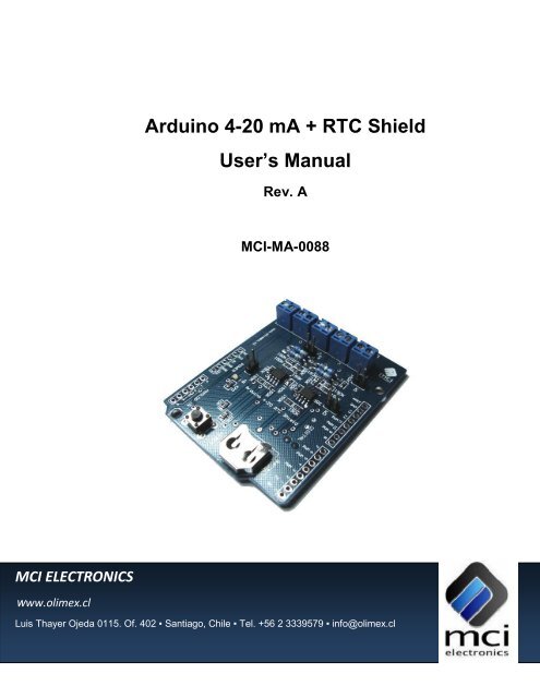
<strong>Arduino</strong> 4-<strong>20</strong> <strong>mA</strong> + <strong>RTC</strong> <strong>Shield</strong><br />
User’s <strong>Manual</strong><br />
Rev. A<br />
MCI-MA-0088<br />
MCI ELECTRONICS<br />
www.olimex.cl<br />
Luis Thayer Ojeda 0115. Of. 402 ▪ Santiago, Chile ▪ Tel. +56 2 3339579 ▪ info@olimex.cl
MCI Ltda.<br />
Luis Thayer Ojeda 0115. Of 402<br />
Santiago, Chile<br />
www.olimex.cl<br />
Tel: +56 2 3339579<br />
Fax: +56 2 3350589<br />
® MCI Ltda. <strong>20</strong>11<br />
Attention: Any changes and modifications done to the device will void its warranty unless<br />
expressly authorized by MCI.<br />
<strong>Manual</strong> Code: MCI – MA - 0088
<strong>Arduino</strong> 4-<strong>20</strong> <strong>mA</strong> + <strong>RTC</strong> <strong>Shield</strong> User’s <strong>Manual</strong> Page 3 of 10<br />
CONTENTS<br />
1 INTRODUCTION ............................................................................................ 4<br />
2 FEATURES .................................................................................................... 5<br />
3 4-<strong>20</strong><strong>mA</strong> SUPPORTED TRANSMITTERS ....................................................... 5<br />
3.1 Type 2 ............................................................................................................ 5<br />
3.2 Type 3 ............................................................................................................ 6<br />
3.3 Type 4 ............................................................................................................ 6<br />
4 SHIELD PARTS .............................................................................................. 7<br />
5 SHIELD INSTALLATION ................................................................................ 8<br />
6 PORT MAPPING .......................................................................................... 10<br />
7 ELECTRICAL CHARACTERISTICS ............................................................. 10<br />
8 MECHANICAL CHARACTERISTICS ............................................................ 10<br />
9 DOCUMENT HISTORY ................................................................................ 10<br />
Luis Thayer Ojeda 0115 Of. 402 ▪ Santiago, Chile ▪ Tel. +56 2 3339579 ▪ info@olimex.cl<br />
www.olimex.cl
<strong>Arduino</strong> 4-<strong>20</strong> <strong>mA</strong> + <strong>RTC</strong> <strong>Shield</strong> User’s <strong>Manual</strong> Page 4 of 10<br />
1 INTRODUCTION<br />
The <strong>Arduino</strong> 4-<strong>20</strong><strong>mA</strong> + <strong>RTC</strong> is a 4-<strong>20</strong><strong>mA</strong> current signal adaptation board. This<br />
<strong>Shield</strong> has 4 input channels which allow converting signals that come with this<br />
industrial standard.<br />
The <strong>Arduino</strong> 4-<strong>20</strong><strong>mA</strong> + <strong>RTC</strong> has a DS1307 Real Time Clock which enables you to<br />
add a time stamp to every converted data. The Real Time Clock has a backup power<br />
supply, using a 12mm Coin type battery.<br />
This <strong>Shield</strong> works with type 2, 3 and 4 current transmitters, and it can be connected<br />
to Duemilanove, Mega and Uno platforms. To work with the <strong>Arduino</strong> 4-<strong>20</strong> <strong>mA</strong> + <strong>RTC</strong><br />
<strong>Shield</strong> you need to connect an external 9-12 VDC power supply for its correct<br />
operation.<br />
With this board you can connect to any industrial sensor, monitor and even control<br />
a variable directly from your <strong>Arduino</strong> board!<br />
Luis Thayer Ojeda 0115 Of. 402 ▪ Santiago, Chile ▪ Tel. +56 2 3339579 ▪ info@olimex.cl<br />
www.olimex.cl
<strong>Arduino</strong> 4-<strong>20</strong> <strong>mA</strong> + <strong>RTC</strong> <strong>Shield</strong> User’s <strong>Manual</strong> Page 5 of 10<br />
2 FEATURES<br />
4 4-<strong>20</strong><strong>mA</strong> input channels.<br />
12mm Coin type battery socket.<br />
Real Time Clock.<br />
o IC DS1307.<br />
o 32kHz clock.<br />
<strong>Arduino</strong> reset button.<br />
4-<strong>20</strong><strong>mA</strong> standards supported.<br />
o Type 2.<br />
o Type 3.<br />
o Type 4.<br />
9-12 VDC power supply.<br />
4 Jumpers for type 3 transmitters.<br />
Power supply connector for sensors.<br />
3 4-<strong>20</strong><strong>mA</strong> SUPPORTED TRANSMITTERS<br />
The <strong>Arduino</strong> 4-<strong>20</strong><strong>mA</strong> + <strong>RTC</strong> <strong>Shield</strong> supports transmitters which work with type 2, 3<br />
and 4 current loops.<br />
3.1 Type 2<br />
Type 2 transmitters are energized by the current loop, where the supply voltage is<br />
included in the receptor. The transmitter is floating and the ground is in the receptor.<br />
Fig. 1: Type 2 transmitter connection schematic.<br />
Luis Thayer Ojeda 0115 Of. 402 ▪ Santiago, Chile ▪ Tel. +56 2 3339579 ▪ info@olimex.cl<br />
www.olimex.cl
<strong>Arduino</strong> 4-<strong>20</strong> <strong>mA</strong> + <strong>RTC</strong> <strong>Shield</strong> User’s <strong>Manual</strong> Page 6 of 10<br />
3.2 Type 3<br />
Type 3 transmitters have 3 wires powered by the source voltage in them. In this<br />
case the transmitter is the power source for the current loop. The transmitter common<br />
is connected to the common of the receptor.<br />
Fig. 2: Type 3 transmitter connection schematic.<br />
3.3 Type 4<br />
Type 4 transmitters have 4 wires powered by the source voltage in them. The<br />
transmitter powers the current loop and the receptor acts a floating load.<br />
Fig. 3: Type 4 transmitter connection schematic.<br />
Luis Thayer Ojeda 0115 Of. 402 ▪ Santiago, Chile ▪ Tel. +56 2 3339579 ▪ info@olimex.cl<br />
www.olimex.cl
<strong>Arduino</strong> 4-<strong>20</strong> <strong>mA</strong> + <strong>RTC</strong> <strong>Shield</strong> User’s <strong>Manual</strong> Page 7 of 10<br />
4 SHIELD PARTS<br />
W4<br />
Channel 1<br />
W1<br />
W2<br />
Channel 2<br />
Battery Socket<br />
Channel 3<br />
Channel 4<br />
<strong>Arduino</strong> Reset<br />
V OUT<br />
V IN<br />
W3<br />
Fig.1: <strong>Arduino</strong> 4-<strong>20</strong><strong>mA</strong> + <strong>RTC</strong> <strong>Shield</strong> top view.<br />
Channel 1 – Channel 4: 4-<strong>20</strong><strong>mA</strong> current signal inputs.<br />
W1-W3: Loop type selection jumpers.<br />
V OUT: Auxiliary power supply output for sensors.<br />
V IN: External power LED indicator.<br />
Battery Socket: 12mm Coin type battery socket.<br />
<strong>Arduino</strong> Reset: <strong>Arduino</strong> board reset button.<br />
Luis Thayer Ojeda 0115 Of. 402 ▪ Santiago, Chile ▪ Tel. +56 2 3339579 ▪ info@olimex.cl<br />
www.olimex.cl
<strong>Arduino</strong> 4-<strong>20</strong> <strong>mA</strong> + <strong>RTC</strong> <strong>Shield</strong> User’s <strong>Manual</strong> Page 8 of 10<br />
5 SHIELD INSTALLATION<br />
Before starting to work with the <strong>Arduino</strong> 4-<strong>20</strong><strong>mA</strong> + <strong>RTC</strong> <strong>Shield</strong>, the following<br />
installation procedure must be done:<br />
A. Position the <strong>Shield</strong> as shown in figure 3.<br />
a. Note that the pin headers that connect the <strong>Shield</strong> to the <strong>Arduino</strong><br />
have only one position.<br />
B. Connect the <strong>Shield</strong> to the <strong>Arduino</strong> main board.<br />
C. Connect the Jumpers depending on the transmitter type.<br />
a. For type 3 transmitters connect Jumpers W1-W4 depending on the<br />
channels to be connected.<br />
b. For type 2 and 3 transmitters disconnect the Jumpers W1-W4<br />
depending on the channels to be connected.<br />
D. Connect the 4-<strong>20</strong><strong>mA</strong> current signal to the desired channel.<br />
E. If required, connect the sensor supply voltage to the V OUT terminal.<br />
F. Connect the <strong>Arduino</strong> main board to the PC using the USB cable.<br />
G. Connect the <strong>Arduino</strong> main board 9-12 [VDC] 600<strong>mA</strong> power supply.<br />
H. Run the test Sketch available on the website.<br />
Luis Thayer Ojeda 0115 Of. 402 ▪ Santiago, Chile ▪ Tel. +56 2 3339579 ▪ info@olimex.cl<br />
www.olimex.cl
<strong>Arduino</strong> 4-<strong>20</strong> <strong>mA</strong> + <strong>RTC</strong> <strong>Shield</strong> User’s <strong>Manual</strong> Page 9 of 10<br />
B<br />
A<br />
C<br />
D<br />
E<br />
Fig. 3: <strong>Arduino</strong> 4-<strong>20</strong> <strong>mA</strong> + <strong>RTC</strong> <strong>Shield</strong> assembly.<br />
Using a 12mm Coin type battery (MCI-PRT-00677) is recommended to maintain<br />
the time configuration on the Real Time Clock embedded with the <strong>Arduino</strong> 4-<strong>20</strong> <strong>mA</strong> +<br />
<strong>RTC</strong> <strong>Shield</strong> in case of a power supply fault.<br />
Luis Thayer Ojeda 0115 Of. 402 ▪ Santiago, Chile ▪ Tel. +56 2 3339579 ▪ info@olimex.cl<br />
www.olimex.cl
<strong>Arduino</strong> 4-<strong>20</strong> <strong>mA</strong> + <strong>RTC</strong> <strong>Shield</strong> User’s <strong>Manual</strong> Page 10 of 10<br />
6 PORT MAPPING<br />
The I/O ports used by the <strong>Arduino</strong> 4-<strong>20</strong><strong>mA</strong> + <strong>RTC</strong> <strong>Shield</strong> cannot be used by<br />
another shield, with the exception of SDA, SCL and RESET signals.<br />
Pin Name Function<br />
ANALOG 0 AN1 Channel 1 analog input<br />
ANALOG 1 AN2 Channel 2 analog input<br />
ANALOG 2 AN3 Channel 3 analog input<br />
ANALOG 3 AN4 Channel 4 analog input<br />
ANALOG 4/SDA SDA SDA signal for communication with Real Time<br />
Clock<br />
ANALOG 5/SCL SCL SCL signal for communication with Real Time<br />
Clock<br />
RESET RESET_ARD <strong>Arduino</strong> board reset<br />
7 ELECTRICAL CHARACTERISTICS<br />
9-12 VDC power supply.<br />
100<strong>mA</strong> maximum current. (not considering transmitters power consumption)<br />
8 MECHANICAL CHARACTERISTICS<br />
Dimensions (WidthxLengthxHeight) 54x69x11 [mm]<br />
9 DOCUMENT HISTORY<br />
Revision Date Edited by Description/Changes<br />
1.0 January 31, <strong>20</strong>11 E. Martin Initial document version<br />
Luis Thayer Ojeda 0115 Of. 402 ▪ Santiago, Chile ▪ Tel. +56 2 3339579 ▪ info@olimex.cl<br />
www.olimex.cl