FF-1 Manual - MGL Avionics
FF-1 Manual - MGL Avionics
FF-1 Manual - MGL Avionics

You also want an ePaper? Increase the reach of your titles
YUMPU automatically turns print PDFs into web optimized ePapers that Google loves.
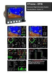
<strong>FF</strong>-1<br />
Fuel management computer for<br />
single or dual fuel tanks<br />
Operating <strong>Manual</strong> – English 1.12<br />
Introduction<br />
The <strong>FF</strong>-1 fuel management computer is a 2 1/4” instrument intended for efficient monitoring of fuel related information for<br />
single or dual fuel tanks onboard small aircraft and related applications.<br />
The <strong>FF</strong>-1 unit can connect to one or two fuel flow senders, one or two fuel level senders or both. Full functionality is<br />
available with both senders or only with a fuel flow sender using calculated fuel levels based on fuel usage. Differential<br />
fuel flow calculations are also supported for fuel return systems. Fuel injector systems are also supported. Standard<br />
automotive fuel level senders can be used, even with odd shaped tanks due to a comprehensive, multi-point calibration<br />
system. Most fuel flow senders can be used and the K-factor of the sender can be entered into the system for simple<br />
calibration. <strong>MGL</strong> <strong>Avionics</strong> supplies a lightweight dual range fuel flow sender that is ideally suited for the <strong>FF</strong>-1, fuel flow<br />
senders from other manufactures (e.g. Floscan) are equally suitable.<br />
In addition, the <strong>FF</strong>-1 can use the airspeed (via the airtalk cable connected to a Infinity ASI-1/ASX-1, Velocity ASI-3/ASX-2<br />
indicator) or actual ground speed (by using the optional GPS NMEA interface cable connected to a RS232 NMEA<br />
enabled GPS receiver) to determine fuel range.<br />
1 Features<br />
• Advanced fuel computer with 20 different modes of operation<br />
• Supports single or dual fuel tanks<br />
• The <strong>FF</strong>-1 can connect to one or two fuel flow senders, fuel level senders or fuel injectors<br />
• Differential fuel flow calculations are also supported for fuel return systems<br />
• The <strong>FF</strong>-1 has the ability to connect to an ASI-1/ASX-1 or a NMEA enabled GPS receiver for range based<br />
calculations. It can also accept a manually entered estimate cruising speed if an ASX-1/GPS is not<br />
available.<br />
• Standard automotive fuel level senders can be used, even with odd shaped tanks due to a comprehensive,<br />
multi-point calibration system<br />
• Bilingual support (English and French)<br />
• Standard 2 1/4” aircraft enclosure (can be front or rear mounted)<br />
• Rotary control plus 2 independent buttons for easy menu navigation and user input<br />
• Alarm output as well as a red LED illuminates when the fuel level is below the fuel level alarm value<br />
• Large backlit graphic LCD with adjustable contrast<br />
• Wide input supply voltage range of 8 to 30V DC with built in voltage reversal and over voltage protection<br />
for harsh electrical environments<br />
• 1 year limited warranty
<strong>FF</strong>-1 Operating <strong>Manual</strong> Page 2<br />
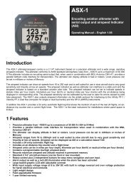
2 <strong>FF</strong>-1 Layout<br />
Backlit graphic LCD display:<br />
Contrast and backlight can be adjusted<br />
in the menu system<br />
LED alarm:<br />
The red LED will illuminate if any of the<br />
fuel tank levels are below the fuel level<br />
alarm value<br />
Harness:<br />
Harness connects to<br />
power, fuel flow and<br />
fuel level senders<br />
Up/F1 Button:<br />
Up button in menu system<br />
Normal mode:<br />
<strong>Manual</strong> speed input if the<br />
speed setting is set to<br />
“MANUAL”<br />
Speed display if the speed<br />
setting is set to “AIRTALK”<br />
or “NMEA”<br />
Down/F2 Button:<br />
Down button in menu<br />
system<br />
Normal mode:<br />
<strong>Manual</strong>ly enter your<br />
current fuel level after<br />
fueling or defueling your<br />
aircraft<br />
Rotary Control (Up/Down) & Enter Button:<br />
Press the rotary control during normal mode to access the menu system. Rotate anti/clockwise<br />
for up/down menu scrolling. During normal mode turning the rotary control will display the<br />
alternate fuel information screen (Display mode dependant, see section 3.1).
<strong>FF</strong>-1 Operating <strong>Manual</strong> Page 3<br />
3 Main Displays<br />
The <strong>FF</strong>-1 has 20 different modes of operation. The display modes can be selected in the fuel setup menu by selecting<br />
different configurations of the number of fuel flow/level senders installed. The <strong>FF</strong>-1 will automatically adjust the display<br />
according to these settings.<br />
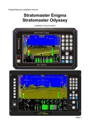
3.1 Single fuel flow and calculated tank level (single tank)<br />
Single fuel flow and fuel level sender (single tank)<br />
Differential fuel flow and calculated tank level (single tank)<br />
Differential fuel flow and fuel level sender (single tank)<br />
Summed fuel flow and calculated tank level (single tank)<br />
Summed fuel flow and fuel level sender (single tank)<br />
Fuel range<br />
Fuel endurance<br />
hours:minutes<br />
Fuel flow<br />
Fuel flow unit<br />
Digital fuel<br />
level value<br />
Fuel level<br />
Fuel low alarm level<br />
Fuel level unit<br />
Alternate main screen for the above display modes<br />
This display can be selected by rotating the rotary control.
<strong>FF</strong>-1 Operating <strong>Manual</strong> Page 4<br />
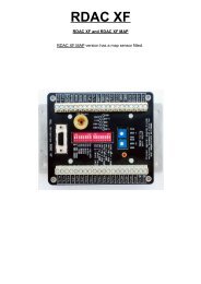
3.2 Dual fuel flow and calculated tank levels (dual tank)<br />
Dual fuel flow and dual fuel level senders (dual tank)<br />
Fuel range<br />
Fuel flow 2<br />
value<br />
Fuel endurance<br />
hours:minutes<br />
Fuel flow 1 value<br />
Fuel flow unit<br />
Fuel tank 1 level<br />
Fuel tank 2 level<br />
Digital fuel<br />
level 1 value<br />
Fuel low alarm level<br />
Digital fuel level 2 value<br />
3.3 Single fuel flow and dual fuel level senders (dual tank)<br />
Single fuel flow, single fuel level sender, single calculated tank<br />
Differential fuel flow and dual fuel level senders (dual tank)<br />
Differential flow, single fuel level sender, single calculated tank<br />
Summed fuel flow and dual fuel level senders (dual tank)<br />
Summed fuel flow, single fuel level sender, single calculated tank<br />
Fuel range<br />
Fuel endurance<br />
hours:minutes<br />
Fuel flow value<br />
Fuel flow unit<br />
Fuel tank 1 level<br />
Fuel tank 2 level<br />
Digital fuel<br />
level 1 value<br />
Fuel low alarm level<br />
Digital fuel<br />
level 2 value
<strong>FF</strong>-1 Operating <strong>Manual</strong> Page 5<br />
Single/Differential/Summed fuel flow, single fuel level sender, single calculated<br />
tank<br />
These modes are nice for multiple fuel tanks whereby one or more tanks are difficult to insert level senders in. Potential<br />
problems such as those listed below can easily be diagnosed by doing side by side comparisons between a calculated<br />
and physical tank.<br />
• Leaks in the fuel system<br />
• Uneven drain of interconnected tanks<br />
• Malfunction of the level sender<br />
• Malfunction of the flow sender<br />
Please note that the fuel flow deducts from the calculated tank only. Fuel range and fuel endurance will only be calculated<br />
if the corresponding fuel flow is setup with the corresponding calculated fuel tank e.g. fuel flow 1 and fuel tank 1.<br />
3.4 Single fuel flow only indicator<br />
This mode is displayed if either fuel flow 1 or fuel flow 2 is selected and no fuel level senders are selected.<br />
Fuel flow value<br />
Fuel flow unit<br />
3.5 Dual fuel flow indicator<br />
This mode is displayed if both fuel flow 1and fuel flow 2 are selected and the fuel mode is selected for dual flow. Both fuel<br />
level senders are disabled.<br />
Fuel flow 1<br />
display<br />
Fuel flow unit<br />
3.6 Single tank level indicator<br />
Fuel flow 2<br />
display<br />
This mode is displayed if either fuel level 1 or fuel level 2 is selected. Both fuel flow senders are disabled.<br />
Remaining fuel<br />
in tank<br />
Fuel level unit<br />
Fuel low alarm<br />
level<br />
Full tank value
<strong>FF</strong>-1 Operating <strong>Manual</strong> Page 6<br />
3.7 Dual tank level indicator<br />
This mode is displayed if both fuel level 1 and fuel level 2 are selected. Both fuel flow senders are disabled.<br />
Remaining fuel in tank 1<br />
Fuel level unit<br />
Remaining fuel<br />
in tank 2<br />
3.8 Differential/Summed fuel flow<br />
This mode is displayed if both fuel flow 1 and fuel flow 2 are selected and the fuel mode is selected for either differential<br />
or summed.<br />
Differential (fuel flow 1 minus fuel flow 2) or<br />
Summed (fuel flow 1 plus fuel flow 2) fuel<br />
flow reading.<br />
Fuel flow unit<br />
Fuel flow reading<br />
from fuel flow<br />
sender 1<br />
Fuel flow reading<br />
from fuel flow<br />
sender 2<br />
3.9 Enter cruising speed<br />
Press the F1 key during the main display screen to manually enter your aircraft’s cruising<br />
speed. This value will be used to calculate the fuel range, i.e. how far you can fly with the<br />
remaining fuel at zero wind speed. For this calculation, your current remaining fuel, your<br />
current fuel flow and the speed entered here are taken into account. You can easily<br />
change the speed during flight to reflect changes in ground speed or cruising speed. Use<br />
this function with care and do not use it to extend your range. You must at all times have a<br />
secondary indication of available fuel. Note that flow senders and level senders may be<br />
subject to malfunction that may result in incorrect fuel levels being displayed or calculated.<br />
This function is only available in certain display modes and if the speed menu option is set<br />
to manual.
<strong>FF</strong>-1 Operating <strong>Manual</strong> Page 7<br />
3.10 Airtalk airspeed / GPS ground speed display<br />
Pressing the F1 key during the main display will show the<br />
current airspeed (using the ASX-1 indicator) or ground<br />
speed (using a NMEA enabled GPS receiver). This value is<br />
used for fuel range calculations.<br />
3.11 Enter starting level of fuel tanks<br />
3.12 Incorrect fuel setup message<br />
Press the F2 key during the main display screen to manually enter your current fuel level<br />
after fueling or defueling your aircraft. This function is only available if you have a mode<br />
selected where fuel level is calculated from fuel flow. Press the F2 key again as a “quick<br />
fill button” to the full level.<br />
Note:It is good airmanship to take into account a “silent” fuel reserve. For example, if you<br />
have a 50 liter tank and you fill it, enter 40 or 45 liters as your available fuel.<br />
The following message will be displayed if the <strong>FF</strong>-1 is setup incorrectly. For example if<br />
both fuel flow senders are disabled and a single/dual fuel level(s) are setup for calculated<br />
fuel tanks.<br />
4 Menu System<br />
Pressing the rotary control button during the normal display mode will cause the <strong>FF</strong>-1 to enter the menu system. Use the<br />
up/down keys or the rotary control to navigate through the menu system.<br />
Note: (“ADC Values” menu item is only visible when powering up the unit and pressing the rotary<br />
control). The text “CALIBRATE” will appear on the intro screen when entering this mode.
<strong>FF</strong>-1 Operating <strong>Manual</strong> Page 8<br />
4.1 Exit Menu<br />
Pressing the rotary control on this menu item will cause the <strong>FF</strong>-1 to exit the menu system. All<br />
changes made during navigation of the menu system will be saved in non-volatile memory on exiting<br />
the menu system. If you remove power before exiting the menu the instrument will not save any<br />
changes.<br />
4.2 Fuel Totals<br />
These are 2 independent accumulators for fuel tank 1 and fuel tank 2 that totalize the amount of fuel<br />
burn since the last time the accumulators were reset to zero.<br />
Move the highlight over the “DONE” menu item and press the rotary control to return to the main<br />
menu.<br />
Select this menu option to reset the fuel totalizers to zero.<br />
4.3 Display Setup<br />
Move the highlight over the “DONE” menu item and press the rotary control to return to the main<br />
menu.<br />
Select this menu option to adjust the display contrast.<br />
Select this menu option to turn the backlight on or off.<br />
Select your preferred language for the <strong>FF</strong>-1. English or French.
<strong>FF</strong>-1 Operating <strong>Manual</strong> Page 9<br />
4.4 Fuel Setup<br />
This menu will customize itself to the various options you choose. The full fuel setup menu is shown.<br />
Move the highlight over the “DONE” menu item and press the rotary control to return to the main<br />
menu.<br />
Select your desired units for distance and fuel quantity. The following options are available:<br />
L/sm: Liters and statute miles<br />
G/sm: U.S. Gallons and statute miles<br />
L/nm: Liters and nautical miles<br />
G/nm: U.S. Gallons and nautical miles<br />
L/km: Liters and kilometers<br />
G/km: U.S. Gallons and kilometers<br />
Select which speed will be used for range based calulations. You can select beteween “MANUAL”<br />
(<strong>Manual</strong>ly enter a cruising speed), “AIRTALK” (airspeed obtained from the ASX-1), or “NMEA”<br />
(obtained from a RS232 NMEA enabled GPS receiver) .<br />
Select the Baud rate of your NMEA GPS receiver.<br />
Select if there is a fuel flow sender connected to the <strong>FF</strong>-1’s fuel flow 1 input.<br />
The K-Factor is the number of pulses generated by the fuel flow sender for one liter of fuel. The dual<br />
range fuel flow sender supplied by <strong>MGL</strong> <strong>Avionics</strong> has a K-Factor of 7000 in the low flow mode (jet<br />
installed) and 1330 for the high flow mode (no jet installed). The Flowscan 201A-6 has a K-Factor of<br />
8454. You can use the K-Factor to calibrate your fuel flow sender. See the installation section for<br />
more details on how to calibrate and install the fuel flow sender.<br />
Select if there is a fuel flow sender connected to the <strong>FF</strong>-1’s fuel flow 2 input.<br />
The K-Factor is the number of pulses generated by the fuel flow sender for one liter of fuel. The dual<br />
range fuel flow sender supplied by <strong>MGL</strong> <strong>Avionics</strong> has a K-Factor of 7000 in the low flow mode (jet<br />
installed) and 1330 for the high flow mode (no jet installed). The Flowscan 201A-6 has a K-Factor of<br />
8454. You can use the K-Factor to calibrate your fuel flow sender. See the installation section for<br />
more details on how to calibrate and install the fuel flow sender.<br />
Select if you want to measure fuel flow using a fuel flow sender or by using fuel injectors.
<strong>FF</strong>-1 Operating <strong>Manual</strong> Page 10<br />
Select whether the <strong>FF</strong>-1 fuel flow input is connected to the high or low side fired fuel injector.<br />
If both fuel flow senders are selected then select if they are operating on individual fuel tanks (dual)<br />
or if they are operating in a supply/return type fuel system (differential).<br />
Select this menu item to setup the fuel level for fuel tank 1. See below for more details.<br />
Select this menu item to setup the fuel level for fuel tank 2. See below for more details.<br />
Fuel level setup. (Only tank 1 setup is shown, follow the same steps<br />
for tank 2 setup)<br />
Move the highlight over the “DONE” menu item and press the rotary control to return to the fuel<br />
setup menu.<br />
Select if fuel tank 1 has a physical fuel level sender connected to it or if the <strong>FF</strong>-1 must use a<br />
calculation based virtual fuel tank. If you do not want any fuel level information then set this<br />
parameter to off.<br />
Enter the size of the fuel tank in your system. It is recommended to choose a size that is slightly less<br />
than actual size so you can compensate for sender inaccuracies and give you a measure of reserve<br />
fuel.<br />
Select whether to turn the fuel tank 1 level alarm on or off.<br />
Enter your desired minimum fuel value that you would like to trigger the fuel low alarm. The fuel low<br />
alarm will result in the flashing of the fuel level display and remaining fuel readout. You can also<br />
connect a warning lamp to the external alarm output (see installation diagram). Note that the fuel low<br />
level will be displayed as a vertical line on your fuel level display. This level is over and above your<br />
“silent” fuel reserve.<br />
See section 4.4.1 on how to calibrate the fuel level senders.<br />
Select the damping factor for the fuel level. A selection of none, low, med or high can be made.
<strong>FF</strong>-1 Operating <strong>Manual</strong> Page 11<br />
4.4.1 Calibrating the fuel level senders<br />
The fuel level sender needs to be calibrated before it can be used with this<br />
system. The calibration allows the system to learn the shape of your tank as well<br />
as any errors your fuel level sender or installation has.<br />
Regardless of your use of a fuel flow sender, you can install a fuel level sender<br />
into your fuel tank. These level senders are inexpensive and are available as<br />
after market replacement fittings from a car spares outlet. We recommend the<br />
senders available from VDO.<br />
Be aware that some makes of cheap level senders can prove troublesome, as the lever arms tend to be sticky.<br />
This prevents the floats from floating on the surface of the fuel at all times. As a consequence, this will lead to<br />
incorrect fuel level indication.<br />
Adjusting calibration points automatically<br />
Select “SENDER” for the mode menu item. Once you have installed a fuel level sender into your tank, make sure the float<br />
can travel all the way from empty to full position without hindrance of any kind. The calibration procedure should be<br />
carried out with your aircraft in flight attitude. This means you need to lift the tail if you have a tail-dragger or lift the nose<br />
wheel if you have a weightshift trike.<br />
Calibration procedure<br />
• Start the calibration procedure with an empty tank.<br />
• Add five liters of fuel (our reserve quantity) using a suitable measure. Make sure the measure is suitably accurate.<br />
This is now the “level sender reading at 0 Lt” position. Move the highlight to this position and wait until the sender<br />
reading has stabilized (You will see the sender reading at the top line). This could take up to a minute so have<br />
patience.<br />
ENSURE THAT THE FLOAT IS NOT SUBMERGED AND IS FLOATING ON TOP OF THE FUEL LEVEL.<br />
Should this number not react to changes of your level sender position, then you have a problem. Please check<br />
your wiring according to the installation section of this manual. You should expect the number to change in the<br />
region of at least 20 to 60 counts per calibration position. If the number does not change with fuel level or only<br />
changes a very small amount – check your installation. Something is not right!<br />
• If you see the number changing then everything is well. Once it has stabilized and the highlight is on the 0 L<br />
position, press the rotary control to transfer the reading from the sender to the calibration point.<br />
• Now you are ready for the next step. Add the required amount of fuel to get to the next level (In our case 9 Lt –<br />
this is 20% tank capacity). Once done, wait for the reading to stabilize and press the rotary control again after you<br />
have moved the highlight to the “9 L” position.<br />
• Proceed in a similar manner until you have reached the last calibration position at 100% tank capacity.<br />
You are done!<br />
To finish your calibration, exit the calibration function by moving the highlight over the “DONE” menu item and<br />
press the rotary control.<br />
The instrument uses the 6 calibration points to work out a correction curve that takes into account the tolerances of your<br />
fuel level sender and the shape of your fuel tank. This results in an incredibly accurate and usable fuel level display that<br />
far exceeds that available from ordinary dial type gauges.
<strong>FF</strong>-1 Operating <strong>Manual</strong> Page 12<br />
Adjusting calibration points manually<br />
You may want to set individual calibration points manually. For example you may<br />
find that your fuel level is over reading at a specific fuel level. Correcting the tank<br />
level reading for this area can be simply done by adjusting the calibration point.<br />
You can do this by moving the float level with your hands to the desired position<br />
and then performing the calibration as outlined above, or you can use the<br />
manual option.<br />
Select “MANUAL” for the mode menu item. Then highlight the point you want to<br />
change manually and press the rotary control. Use the up or down keys or the<br />
rotary control to adjust the value. Press the rotary control when done.<br />
Note: The calibration positions may be edited by using the up and down keys. This allows you, in theory, to copy<br />
calibration settings from one instrument to another. We however recommend that you do go though the calibration<br />
procedure even if the two aircraft are identical in all respects. Tolerances do exist and the calibration cancels these out.<br />
Accurate fuel level displays are a vital safety factor for an aircraft and a very useful feature for peace of mind during cross<br />
county flights.<br />
Notes on Slope error<br />
Sender value is a value determined by the <strong>FF</strong>-1. It is used to calculate fuel level,<br />
fuel endurance estimate and current range estimate. The fuel tank setup sender<br />
value can either increase in value as fuel is added or decrease in value if fuel is<br />
added. This is dependent on the type of fuel level sender used. However should<br />
the second reading be larger than the first reading all readings will have to be<br />
larger than the previous readings. Likewise should the second reading be<br />
smaller than the first reading all readings will have to be smaller than the<br />
previous reading.<br />
If this is not the case the wording "Slope error" will be displayed. This could happen when fuel was removed instead of<br />
added between steps, no fuel was added between steps or when the fuel level sender was moved in the wrong direction<br />
e.g. moving the fuel level sender manually when it is not inserted in to the fuel tank. Determine the cause of the error if<br />
you should get a slope error message. If you do not know the cause of your error it is best to start from scratch. It should<br />
be remembered that accuracy in the fuel tank calibration is extremely important to enable your <strong>FF</strong>-1 to display the correct<br />
data.<br />
4.5 ADC Values<br />
Note: This menu item is for technical personnel only, and is not displayed during the normal<br />
operation of the instrument. Please see section 4 above on how to access this menu item.<br />
This menu displays the ADC values that have been read from the two fuel level senders.
<strong>FF</strong>-1 Operating <strong>Manual</strong> Page 13<br />
5 Loading factory default settings<br />
Pressing and holding the F1 and F2 keys simultaneously on power up will cause the <strong>FF</strong>-1 to load preprogrammed factory<br />
default settings. The following screen will be displayed:<br />
6 Operating the alarms<br />
If the alarm is activated, the corresponding item on the display will flash. At the same time the externally available alarm<br />
switch will close. The switch will remain closed until any button is pressed to acknowledge the alarm or until the<br />
condition(s) that activated the alarm no longer exist. The alarm output can be used to switch an external alarm indicator.<br />
The external alarm switch is an open collector transistor switch to ground with a maximum rating of 0.5A DC. It is possible<br />
to wire the alarm contacts of several Stratomaster instruments in parallel should this be desired. To avoid false activation<br />
of the alarms, the alarm function is only active 10 seconds after the instrument has powered up.<br />
7 Airtalk speed input message<br />
The <strong>FF</strong>-1 will accept a speed message from an airspeed type indicator such as a Stratomaster Infinity ASX-1 (Encoding<br />
aviation altimeter with serial output and airspeed Indicator (ASI)). The <strong>FF</strong>-1 uses this information to calculate the fuel<br />
range, i.e. for how far you can fly with the remaining fuel. For this calculation, your current remaining fuel, your current<br />
fuel flow and the speed information are taken into account.<br />
The <strong>MGL</strong> avionics airtalk protocol uses 19200 baud, 8 data bits, one stop bit and no parity.<br />
8 RS232 NMEA enabled GPS receiver message<br />
The Infinity <strong>FF</strong>-1 has the ability to be connected to a NMEA enabled RS232 GPS receiver to allow the <strong>FF</strong>-1 to use the<br />
actual ground speed in determining the fuel range. For this calculation, your current remaining fuel, your current fuel flow<br />
and the ground speed information are taken into account. The Baud rate can be setup in the <strong>FF</strong>-1 for 1200 to 19200<br />
Baud. An additional GPS NMEA interface cable is required.<br />
The NMEA enabled RS232 GPS receiver must be able to output a GPRMC message (The Recommended Minimum<br />
sentence defined by NMEA for GPS/Transit system data.) This message is defined as:<br />
$GPRMC,hhmmss,status,latitude,N,longitude,E,spd,cog,ddmmyy,mv,mvE,mode*cs<br />
Example: $GPRMC,083559.00,A,4717.11437,N,00833.91522,E,0.004,77.52,091202,,,A*57
<strong>FF</strong>-1 Operating <strong>Manual</strong> Page 14<br />
9 Cleaning<br />
The unit should not be cleaned with any abrasive substances. The screen is very sensitive to certain cleaning materials<br />
and should only be cleaned using a clean, damp cloth.<br />
Warning: The <strong>FF</strong>-1 is not waterproof. Serious damage could occur if the unit is exposed to water<br />
and/or spray jets.<br />
10 <strong>FF</strong>-1 Specifications<br />
Operating Temperature Range -10ºC to 50ºC (14ºF to 122ºF)<br />
Storage Temperature Range -20ºC to 80ºC (-4ºF to 176ºF)<br />
Humidity<br />
<strong>FF</strong>-1 Operating <strong>Manual</strong> Page 15<br />
11.2 Connection Diagram<br />
The use of an external 1A fuse is recommended. Connect the supply terminals to your aircrafts power supply. The <strong>FF</strong>-1<br />
can be used on both 12V and 24V without the use of any pre-regulators. Ensure that the supply voltage will not drop<br />
below 8V during operation as this may result in incorrect displays.
<strong>FF</strong>-1 Operating <strong>Manual</strong> Page 16<br />
11.3 Fuel flow sender installation<br />
The fuel flow sender allows the <strong>FF</strong>-1 to provide instantaneous readouts of hourly fuel usage, and both time and distance<br />
estimates on remaining fuel in flight. You can also verify the performance of your fuel pump during the pre-takeoff engine<br />
run up – a very valuable check! Further, it is possible to set up the instruments to calculate fuel remaining by subtracting<br />
fuel used from a value entered when you filled your tank(s). In this case you may omit the installation of the optional fuel<br />
level sender. Please note that the installation of the fuel Flow sender should be done in such a fashion that dirt or debris<br />
from the fuel tank cannot lodge inside the flow sender. These will not block you fuel flow but may lead to the impeller<br />
inside the sender jamming. It is usually sufficient to mount the flow sender AFTER the fuel filter but before the fuel pump.<br />
It is a good idea to provide a small reservoir such as a primer bulb between the flow sender and the fuel pump.<br />
As indicated in the recommended installation drawing, it can be of advantage to install the flow sender in such a fashion<br />
that the inlet points slightly down and the outlet points slightly up. This prevents vapor from forming a bubble inside the<br />
flow sender. We strongly recommend mounting the flow sender in such a fashion that the impeller rests on only one<br />
bearing. This is achieved if you mount the sender such that the surface with the arrow faces upwards. Mounting the<br />
sender like this results in the best performance at low flow rates as only very little friction is present. The flow sender is<br />
delivered with a small jet that can be installed in the flow sender inlet. Installation of this jet is recommended for engines<br />
with fuel flow rates lower than about 30 liters per hour. This would apply to most small two and four stroke engines. The<br />
<strong>FF</strong>-1 is shipped with the fuel flow sender calibration set for the jet installed. In a good installation you can expect about +/-<br />
3% maximum flow reading error with this factor. You can calibrate the flow sender yourself to a higher degree of accuracy<br />
if you so desire.<br />
Recommended procedure to calibrate the fuel flow sender:<br />
Note: You must disable the fuel level sender if you have one installed, and enable the calculated fuel level sender.<br />
1. Fill your tank exactly to a known level (for example 50 liters).<br />
2. Set your fuel level to 50 liters.<br />
3. Fly your aircraft for a period that you know will use approximately 20 liters of fuel. The exact fuel burn is not<br />
important; just burn about 20 liters of your fuel. At the end of your flight the instrument should give you a reading<br />
of how much fuel you have left – the reading should be about 30 liters left.<br />
4. Now place your aircraft in exactly the same position that you used when you first filled the tank and refill the tank<br />
to 50 liters using a measuring jug. You should find that you need 20 liters of fuel to refill to 50 liters.<br />
5. If you find that the instrument under or over reads the fuel used, you should perform a simple adjustment of the<br />
fuel flow sender calibration factor.<br />
Example:<br />
Actual fuel used: 21.5 liters, <strong>FF</strong>-1 fuel burn calculated 29.7 liters left in the tank. This means the <strong>FF</strong>-1 measured 50-29.7 =<br />
20.3 liters. We are under reading by 1.2 liters.<br />
Default calibration factor in Fuel setup menu = 7000.<br />
Let the corrected calibration factor be X.<br />
X = (20.3 * 7000) / 21.5<br />
X = 6609.3<br />
The closest setting you can enter as factor is 6609. Enter it into the unit and you are done!<br />
Repeat the above procedure to verify that your flow sender is now reading correctly.<br />
Please note:<br />
Before you calibrate the flow sender ensure there are no problems with your installation. We find the senders are very<br />
accurate if everything is installed and working properly. If your fuel burn indication is out by a large amount you have a<br />
problem that you should not attempt to fix by fiddling with the calibration factor! Please ensure that no fuel vapor can be<br />
trapped inside the sender housing in the form of bubbles. Due to the low fuel flow rates the bubbles will prevent the tiny<br />
impeller from turning freely, you can verify the turning of the impeller. You should notice three dark spots that are just<br />
visible in the inside of the fuel flow sender. These are small magnets that are attached to the impeller. With fuel flowing<br />
you should see the magnets turning. The best defense against vapor bubbles is to install the flow sender in such a way<br />
that the bubbles can escape. The easiest way is to point the outlet slightly upwards and the inlet (with the jet) slightly
<strong>FF</strong>-1 Operating <strong>Manual</strong> Page 17<br />
downwards. Another possible problem is the fuel sender jet. When you install it, do not damage it. Use a drill bit of<br />
suitable diameter (5.5mm) to push the jet all the way, the opening of the jet must be just in front of the impeller.<br />
YOU NEED TO APPLY SOME FORCE TO INSERT THE JET ALL THE WAY (about 24mm). THE JET MUST BE<br />
LOCATED RIGHT IN FRONT OF THE IMPELLOR. YOU CANNOT PUSH THE JET TOO FAR.<br />
Using other Flow Senders<br />
It is quite possible to use flow senders other than the <strong>MGL</strong> <strong>Avionics</strong> fuel flow sender. In this case ensure that the sender<br />
outputs a 5V TTL square wave or a similar signal. The <strong>FF</strong>-1 interface electronics will adapt to a variety of different<br />
voltages and pulse shapes as it contains a Schmitt-trigger input stage. The calibration factor can be entered in a wide<br />
range making the unit particularly suited to other flow senders. The supply output terminal for the sender provides a<br />
positive, regulated 5 volt output. This may be used to power the flow sender provided the sender will not draw more than<br />
40 mA of current. Should your sender require a higher voltage or more current, you must supply the sender from a<br />
different power source. Exceeding the rating on the <strong>MGL</strong> <strong>Avionics</strong> fuel flow sender supply terminal can affect the<br />
operation on the unit negatively or even damage it. Some senders require a pull-up resistor to the 12V supply line. We<br />
find most installations of these senders require a 4K7 pull-up resistor.<br />
Recommended Calibration Factors for the <strong>MGL</strong> <strong>Avionics</strong> dual range flow sender:<br />
With jet installed = 7000. Recommended for flow rates below 30 liters/hour maximum<br />
Without jet installed = 1330. Recommended for flow rates above 30 liters/hour<br />
Please refer to the leaflet included with the flow sender for information on pressure drop versus flow rate, wetted materials<br />
etc.<br />
It is your responsibility to ensure that the flow sender used is compatible with the fuels you intend using. We<br />
have found the <strong>MGL</strong> <strong>Avionics</strong> fuel flow sender to be very compatible with automotive fuels used in South Africa,<br />
many of which contain methanol. 100LL AVGAS also appears not to harm the sender in any way. We have<br />
exposed a sender continuously to our automotive fuels for the duration of two years without any noticeable ill<br />
effect on the sender. However, despite this <strong>MGL</strong> <strong>Avionics</strong> or its appointed agents cannot assume responsibility<br />
for any incident or damage, even loss of life by whatsoever cause connected with the fuel flow sender or the <strong>FF</strong>-1<br />
instrument. Usage of this or other senders is your own sole responsibility.<br />
If you do not agree with the above statement you must not use the fuel flow sender.<br />
Note to Pilots: (Even though this is the installation manual)<br />
You must always have a visual indication of the fuel level available, either by means of a sight glass, direct tank<br />
observation or a known, reliable secondary fuel level gauge. Fuel level indication by means of calculated fuel burn is<br />
subject to errors both by entering incorrect starting fuel levels as well as mechanical problems causing the flow sender<br />
impeller to turn too slowly, resulting in under reading fuel burn and thus over reading remaining fuel. As pilot in command<br />
of an aircraft it is your responsibility to ensure that you have sufficient fuel to reach your intended destination. Always<br />
ensure that you have a generous amount of reserve fuel and never use your reserve fuel except in an emergency if it is<br />
unavoidable.<br />
11.4 Floscan 201 fuel flow sender installation<br />
1. The inlet and outlet ports in series 201 flow transducers have ¼” NPT threads. Use only ¼” NPT hose or pipe<br />
fittings to match. When assembling fittings into the inlet and outlet ports DO NOT EXCEED a torque of 15 ft. lbs.<br />
(180 inch lbs.), or screw the fittings in more than 2 full turns past hand tight, WHICHEVER COMES FIRST.<br />
FloScan Instrument Co., Inc. will not be responsible for cracked castings caused by failure to use ¼” NPT fittings,<br />
over torquing the fittings, or assembling them beyond the specified depth.<br />
2. A screen or filter should be installed upstream of the flow transducer to screen out debris which could affect rotor<br />
movement or settle in the V-bearings. As turbulence upstream of the transducer affects its performance, there<br />
should be a reasonable length of straight line between the transducer inlet and the first valve, elbow, or other<br />
turbulence-producing device.<br />
3. Install the flow transducer with wire leads pointed UP to vent bubbles and insure that rotor is totally immersed in<br />
liquid. For maximum accuracy at low flow rates the transducer should be mounted on a horizontal surface.<br />
4. Power supply: 12 VDC at 100mA filtered and regulated.
<strong>FF</strong>-1 Operating <strong>Manual</strong> Page 18<br />
5. Series 200 flow transducers are designed to measure steady state flows. Indicated accuracies and pulse counts<br />
were obtained using heptane on a flow stand with rotary pumps and are reproducible in flow systems using rotary<br />
or gear pumps. Fuel systems with diaphragm fuel pumps and carburetors produce pulsating fuel flows. For<br />
accurate results on these systems consult the factory for the correct flow transducer/pulsation damper<br />
combination.<br />
Wiring the Floscan Flow Transducer<br />
The <strong>FF</strong>-1 unit measures the output from the transducer. A 5600 ohm (5k6) pull-up resistor is required. See wiring table<br />
and installation diagram below.<br />
The gallon per hour K-Factor for the 201A-6 transducer is approximately 32,000. The K-Factor of each sensor (at 16<br />
GPH), divided by 10, is written on a label attached to sensor. Multiply this number on the label by 10, which should give a<br />
value of approximately 32,000. The <strong>FF</strong>-1 requires a litre per hour K factor. Take the gallon per hour K factor, and divide it<br />
by 3.785 (which yields a K-Factor of approximately 8454).<br />
Floscan transducer wire color<br />
White<br />
Black<br />
Red<br />
<strong>FF</strong>-1 DB9 Terminal/Other Terminal<br />
Fuel flow sender 1 (DB9 pin 5 – Blue)<br />
Fuel flow sender 2 (DB9 pin 8 – yellow)<br />
<strong>FF</strong>-1 ground (DB9 pin 1 – Black) / Aircraft<br />
ground / Engine block<br />
+12V DC Supply (Not supplied by the <strong>FF</strong>-1)<br />
Floscan connection diagram
<strong>FF</strong>-1 Operating <strong>Manual</strong> Page 19<br />
Model 201A-6 Model 201B-6 Model 201C-6<br />
Flow range: Gasoline 0.3 – 30 GPH 0.6 – 60 GPH 2.0 - 80 GPH<br />
Flow range: #2 Diesel 2.0 – 30 GPH 3.0 – 60 GPH 8.0 – 80 GPH<br />
Approximate K-Factor¹: Gasoline 32 000 28 000 – 31 000 24 000<br />
Approximate K-Factor¹: Diesel 33 000 28 000 25 000<br />
Pressure Drop: Gasoline 0.6psi @ 15 GPH 1.2psi @ 30 GPH 1.4psi @ 40 GPH<br />
2.4psi @ 30GPH 4.8psi @ 60GPH 5.8psi @ 80 GPH<br />
Pressure Drop: #2 Diesel 0.8psi @ 15GPH 1.5psi @ 30GPH 1.8psi @ 40GPH<br />
3.0psi @ 30GPH 6.0psi @ 60GPH 7.2psi @ 80GPH<br />
Repeatability between measurements 0.25% @ 16GPH 0.25% @ 16GPH 0.25% @ 16GPH<br />
Working pressure 200psi 200psi 200psi<br />
Temperature range -65º/100ºC -65º/100ºC -65º/100ºC<br />
Bearing life expectancy 10 000 hr min. 10 000 hr min. 10 000 hr min.<br />
Notes:<br />
1. Pulses/Gallon @ 16 GPH<br />
2. All flow transducers are tested and marked with K-factor at 16 GPH. Repeatability at 16 GPH is guaranteed to 0.25%.<br />
Transducers are available with calibrated K-factors at additional cost<br />
11.5 Fuel level sender installation<br />
The <strong>FF</strong>-1 permits the connection of one or two standard automotive fuel level senders. These senders can be obtained at<br />
automotive spares outlets at reasonable cost. When you choose a float level sender, ensure that you select a model that<br />
is sturdy and promises reliable and long lifetime. In particular, select a model that does not have any metal parts that can<br />
rust. The <strong>FF</strong>-1 can interface to a large variety of these fuel level senders. It does not matter if the sender resistance<br />
increases or decreases with the fuel level as long as it changes. The calibration procedure outlined in the “Fuel Setup”<br />
section describes in great detail the procedure to follow.<br />
In essence, the calibration procedure will measure the resistance of the fuel level sender at various fuel levels and then<br />
work out the readings in between those known settings. Typical fuel level senders that can be used with the <strong>FF</strong>-1 have<br />
resistance ranges in the region of 100 ohms to 500 ohms. Connect the flange of the sender to the negative supply<br />
(ground). You can connect capacitive senders as well. These generally come in two types: The first emulates a normal<br />
resistive probe and is simple to connect and use as a result. The second type has a voltage level output. These can be<br />
used if the voltage can be set to a range of about 0-5V. Higher voltage levels will result in the instrument assuming a<br />
problem. The <strong>FF</strong>-1 supports one or two fuel tank level senders. You need to enable these in the “Fuel Setup” menu.<br />
We recommend using VDO float based fuel level senders. Capacitive types can be used provided they have a voltage<br />
output not exceeding 5V. The level terminal has an internal 1K resistor pull-up to 5V. Please note that capacitive senders<br />
may exhibit large errors as they are very sensitive to the composition of the fuel used. We do not recommend using<br />
capacitive senders with automotive fuels for this reason.<br />
Safety Hazard! Please take note:<br />
Be careful when installing fuel level senders into fuel tanks. Ensure that the fuel tank is completely empty<br />
when you proceed with the installation. Ensure that the fuel tank is well ventilated and does not contain any<br />
fuel vapors – these are highly explosive when mixed with air. Ensure that at all times the ground<br />
connection (the connection of the fuel level sender mounting flange) is securely connected to the aircraft<br />
frame (in case of a metal frame) and to the negative terminal of the battery. In addition the negative<br />
terminal of the battery must at all times be connected to the supply ground terminal of the <strong>FF</strong>-1. Please<br />
note – this wiring is critical and must never break in flight. It would be possible to create electrical sparks in<br />
the fuel tank if your wiring is faulty or incorrect. The consequences of this can be imagined. This has<br />
nothing to do with the <strong>FF</strong>-1 itself but is a general hazard for any automotive fuel level sender installation. If<br />
you have no experience with electrical wiring, PLEASE delegate the task to a qualified automobile<br />
electrician or electronics technician. If you need to remove the <strong>FF</strong>-1, please first disconnect and secure the<br />
fuel level sender wire before disconnecting anything else.
<strong>FF</strong>-1 Operating <strong>Manual</strong> Page 20<br />
11.6 Fuel injector systems<br />
Should you want to monitor fuel flow directly by means of measuring the fuel injector opening time, the connection as in<br />
the diagram below can be used. You can use either high or low fired injectors (most systems are low side fired as shown<br />
below). After you have connected the system as shown below you can proceed to set up the system. (don’t forget that<br />
you need a connection from the <strong>FF</strong>-1 ground terminal to the engine block (at the same potential as the battery negative).<br />
• Select high or low side fired injector in the Fuel Setup menu.<br />
• Enable the flow sender in the Fuel Setup menu.<br />
• Select a suitable K-factor in the calibration menu to give you correct rate of flow. A good starting value may be in<br />
the 1500-2000 range. Increase to lower indicated flow and decrease to have a larger indicated flow.<br />
Flow through the injectors may not be 100% linear with switching times due to various effects. However, it is possible to<br />
obtain very good performance from this flow monitoring system if you keep the following in mind: Calibrate the K-factor so<br />
flow indication is accurate during cruise, the period your engine spends most of its active time at. Ensure that you have a<br />
correctly working fuel pressure regulator. The more constant your fuel pressure, the more accurate the flow indication.<br />
Never use this or any other flow system as your only fuel level indication. This is not the intended purpose of a<br />
flow measuring system and this can be dangerous if for whatever reason incorrect flow is indicated.
<strong>FF</strong>-1 Operating <strong>Manual</strong> Page 21<br />
12 Warranty<br />
This product carries a warranty for a period of one year from date of purchase against faulty workmanship or defective<br />
materials, provided there is no evidence that the unit has been mishandled or misused. Warranty is limited to the<br />
replacement of faulty components and includes the cost of labour. Shipping costs are for the account of the purchaser.<br />
Note: Product warranty excludes damages caused by unprotected, unsuitable or incorrectly wired<br />
electrical supplies and or sensors, and damage caused by inductive loads.<br />
13 Disclaimer<br />
Operation of this instrument is the sole responsibility of the purchaser of the unit. The user must make themselves familiar<br />
with the operation of this instrument and the effect of any possible failure or malfunction.<br />
This instrument is not certified by the FAA. Fitting of this instrument to certified aircraft is subject to the rules and<br />
conditions pertaining to such in your country. Please check with your local aviation authorities if in doubt. This instrument<br />
is intended for ultralight, microlight, homebuilt and experimental aircraft. Operation of this instrument is the sole<br />
responsibility of the pilot in command (PIC) of the aircraft. This person must be proficient and carry a valid and relevant<br />
pilot’s license. This person has to make themselves familiar with the operation of this instrument and the effect of any<br />
possible failure or malfunction. Under no circumstances does the manufacturer condone usage of this instrument for IFR<br />
flights.<br />
The manufacturer reserves the right to alter any specification without notice.<br />
Other instruments in the Stratomaster Infinity series<br />
ALT-1 Precision encoding altimeter and vertical speed indicator<br />
ALT-2 Precision encoding altimeter and vertical speed indicator with a serial RS232<br />
transponder output<br />
ASI-1 Airspeed indicator (ASI) with automatic flight log<br />
ASX-1 Encoding aviation altimeter with serial output and airspeed indicator (ASI)<br />
AV-1 Artificial horizon and magnetic compass indicator<br />
BAT-1 Battery voltage and current monitor<br />
E-3 Universal engine monitor<br />
<strong>FF</strong>-1 Fuel Computer (single or dual fuel tanks)<br />
GF-1 +-10G tilt compensated dual range G-force meter<br />
MAP-1 Manifold pressure and RPM Indicator<br />
RV-1 Universal engine RPM and rotor RPM Indicator<br />
RV-2 Universal turbine RPM / RPM factor display<br />
RTC-2 Aviation real time clock (RTC) and outside air temperature (OAT) display<br />
TC-1 4-Channel thermocouple indicator<br />
TP-1 Universal temperature and pressure gauge