TC-4 Manual - Innovate Motorsports
TC-4 Manual - Innovate Motorsports
TC-4 Manual - Innovate Motorsports

Create successful ePaper yourself
Turn your PDF publications into a flip-book with our unique Google optimized e-Paper software.
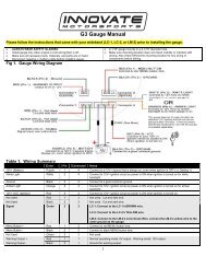
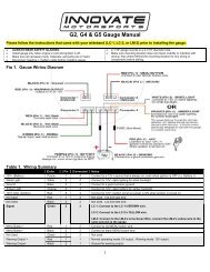
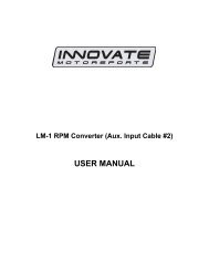
<strong>TC</strong>-4 4 Channel Thermocouple Interface<br />
User <strong>Manual</strong><br />
<strong>TC</strong>-4 <strong>Manual</strong> 1.1.doc
1. Overview............................................................................................................................... 3<br />
2. Specifications........................................................................................................................ 3<br />
3. Thermocouple Basics ........................................................................................................... 4<br />
4. Connecting the <strong>TC</strong>-4............................................................................................................. 5<br />
4.1 Connecting power ............................................................................................................. 5<br />
4.2 Connecting Thermocouples.............................................................................................. 5<br />
5. The <strong>Innovate</strong> Log-Chain concept ......................................................................................... 6<br />
5.1 Log-Chain of 4 channels consisting of <strong>TC</strong>-4 alone........................................................... 7<br />
5.2 6-channel Log-Chain example with 2 AFR channels........................................................ 7<br />
5.3 16-Channel Log-Chain example ....................................................................................... 8<br />
6. Programming the <strong>TC</strong>-4 with LM Programmer ...................................................................... 8<br />
6.1 Changing the device name ............................................................................................... 9<br />
6.2 Updating the firmware....................................................................................................... 9<br />
6.3 Configuring the Inputs....................................................................................................... 9<br />
7. Kit Contents ........................................................................................................................ 10<br />
Appendix A: Limited Warranty...................................................................................................... 11<br />
Revision History............................................................................................................................. 11<br />
- 2 -
1. Overview<br />
The <strong>TC</strong>-4 device is 4 channel thermocouple interface device for a MTS Log Chain. The <strong>TC</strong>-4 may<br />
also be used as a stand-alone 4 channel MTS compatible thermocouple amplifier (see Chapter 2<br />
for more details).<br />
Each of the four inputs of the <strong>TC</strong>-4 can be user configured either EGT range (32..1999 degF,<br />
0..1093 degC) or for CHT range to measure cylinder head temperatures (32..572 degF, 0..300<br />
degC.<br />
2. Specifications<br />
Power<br />
Power requirements 8-36 Volt / 50mA see Note 1<br />
Power reversal protection Yes<br />
External Sensor power 5V (+- 2.5%), 300mA max.<br />
Serial Communication<br />
Serial Port Speed<br />
Packet/Logging Speed<br />
Sample Resolution<br />
19.2 kbit/sec<br />
81.92 msec/sample packet<br />
10 bits (0..5V at 0.1% resolution)<br />
Input Specifications<br />
Number of Channels 4<br />
Thermocouple Type<br />
Type K<br />
Input measurement range 0 to 300 degC (CHT Range) or<br />
0 to 1093 degC (EGT Range)<br />
CHx+ max input voltages - 2.5V to +7.5V<br />
CHx- max input voltages -2.5V to +7.5V<br />
Common Mode Rejection -2.5V to +7.5V<br />
Range<br />
Input Impedance<br />
1 MOhm<br />
Temperature<br />
Max Operating Temperature<br />
Mechanical<br />
Size (W x L x H)<br />
Weight<br />
-20 to +80 deg Celsius<br />
133 x 65 x 26 mm<br />
114 grams<br />
Note 1: Supply current does not included current of external sensors powered from the 5V output<br />
- 3 -
3. Thermocouple Basics<br />
Thermocouples are used to measure temperatures by relying on the phenomenon where a<br />
junction of any two different metals ( Copper and Iron, for example ) will generate a small<br />
voltage. This voltage is dependant upon which two metal are used, and the temperature of the<br />
junction. This phenomena is known, formally, as the "Seebeck Effect". Because every junction<br />
of different metals contributes its own voltage into the measurement, it is important to have as<br />
few junctions between dissimilar metals as possible in order to record an accurate<br />
measurement. This is why thermocouple wire is made completely of two different metals. The<br />
"Type K" thermocouple to be used with the <strong>TC</strong>-4 kit is composed of Cromel and Alumel; one lead<br />
being made of each ( the red and yellow leads ).<br />
To make a thermocouple, strip approximately 3/4" of insulation form one end of the thermocouple<br />
wire. Twist the two exposed metal ends together. You may optionally solder them, also. But<br />
twist them first. Do not solder them in parallel. This will form what is called the "Hot junction".<br />
This "Hot junction" is what you will connect to the surface that you want to measure. This is<br />
usually either: a) under the copper gasket of a sparkplug for cylinder head temperature<br />
(CHT) or, b) clamped to a primary header tube for exhaust gas temperature (EGT). Note that<br />
clamping to the primary tube will NOT measure real EGT, but the surface temperature of the<br />
header pipe. For real EGT measurements use an EGT probe that extends into the header itself.<br />
There is also the "Cold junction." This is where the 2 leads of the thermocouple come together<br />
again at the <strong>TC</strong>-4 terminals. The <strong>TC</strong>-4 has an internal temperature sensor at the T/C input<br />
terminals. It uses this sensor to "offset" the effect of the "Cold junction" in the measurement.<br />
This is called "Cold junction compensation". Once the effects of the cold junction are neutralized,<br />
the <strong>TC</strong>-4 can accurately read the temperature of the "Hot junction" which is the twisted lead pair<br />
at the opposite end of the thermocouple wire.<br />
- 4 -
4. Connecting the <strong>TC</strong>-4<br />
The <strong>TC</strong>-4 looks like this:<br />
4.1 Connecting power<br />
Connect switched 12V power (switched on when the cars ignition system is on) from the car to<br />
the terminal marked 12V on the <strong>TC</strong>-4 connector.<br />
Connect one of the terminals marked GND to a good ground on the car. The engine block will<br />
supply a good ground connection.<br />
4.2 Connecting Thermocouples<br />
One thing that is counter intuitive for many people is that the negative side of a thermocouple<br />
wire is always red. There are many different types of thermocouple wire; types K, J and T being<br />
the most popular. All have a red negative lead and a yellow, black, or blue positive lead<br />
respectively. When connection the thermocouple to the terminals on the <strong>TC</strong>-4, be sure to<br />
connect the yellow lead to the + and red lead to the - terminals.<br />
Several manufacturers offer EGT "thermocouple probes" which are actually inserted into the<br />
exhaust gas stream through a hole in the headers or exhaust manifold. These provide a more<br />
accurate measurement of exhaust gas temperature. They are commonly available in types K<br />
and J. Only type K will currently work with the <strong>TC</strong>-4. To use a thermocouple probe, connect the<br />
red and yellow leads of the thermocouple wire to the yellow and red leads of the thermocouple<br />
probe. The junction is inside the probe. You can not use normal copper wire to connect the<br />
thermocouple probe to the <strong>TC</strong>-4. You must use thermocouple wire to connect the probe. If you<br />
do not, there will be an extra two-metal junction where the Copper wire meets the wires of the<br />
probe. This extra junction will cause a large error in the temperature readings.<br />
- 5 -
Most Thermocouple probes are of the “grounded junction” type. This means that the “hot<br />
junction” is also connected to the probe’s body. As this body is connected for example to the<br />
exhaust manifold, the sensor wires are essentially grounded through that. The same would be<br />
true if a home-made thermocouple junction is used as described above by twisting the wires and<br />
if that wire-twist is connected to some grounded engine part. If the twisted ends would be<br />
grounded, untwist them first and clamp the separately but close together. Otherwise the clamping<br />
metal part can short out part of the thermocouple voltage. See below:<br />
The <strong>TC</strong>-4 will work with either isolated or grounded junction thermocouples.<br />
There are four GND connections. The two closest to the 5V terminal can be used for<br />
thermocouple shielding. The GND terminals next to the <strong>TC</strong>4- terminal are no-connects so they<br />
are not to be used.<br />
5. The <strong>Innovate</strong> Log-Chain concept<br />
LogWorks 2.0 has the capability to log, display and analyze up to 32 engine parameters. Most<br />
users will use less though. Each of the MTS components reads between 1 and 6 engine<br />
parameters. To interface a multitude of MTS components to LogWorks with a single connection,<br />
the <strong>Innovate</strong> LogChain concept was introduced.<br />
The <strong>TC</strong>-4 can be used as a MTS component in a Log-Chain.<br />
Each of the MTS components has two serial ports (except the LM-1, which has only one). One<br />
serial port is designated as IN-port, the other as OUT port. The OUT-port of one device is<br />
connected to the IN-port of the next device and so on. This way devices can be ‘daisy-chained’ to<br />
build a log-chain for up to 32 channels total. The OUT-port of the last device is connected to the<br />
computer for logging or downloading of logged data.<br />
The device that’s first in the chain is special. It determines the logging sample rate. The first<br />
device in the chain sends a data packet containing its channel data (a sample) to the next device<br />
(downstream, left to right in the diagram) every 81.92 milliseconds. The next device appends its<br />
data to that packet and hands that packet to the next device downstream and so on. At each<br />
device the packet grows in length. The devices in the chain synchronize their sampling of the<br />
engine parameters to the packets, so that all the channels in a packet together represent the<br />
same instance in time. At the downstream end of the log chain (OUT-port of the last device) a<br />
computer or external logger can be connected to store or display the stream data. The XD-1<br />
display is such a device.<br />
- 6 -
This also means that the complete channel data set is ONLY available at the end of the<br />
log-chain. A datalogger capable of recording the log-chain data-stream therefore MUST be<br />
placed at the end of the log-chain. This includes lap-top computers or other loggers.<br />
Commands for individual devices are sent ‘upstream’. A device (incl. a computer or an XD-1) can<br />
send commands to the devices upstream of itself, but not downstream. Commands can include<br />
start-stop recording, calibration/configuration commands and so on. Only the device directly<br />
upstream of the command originator of course will receive the command. This device then<br />
decides, depending on the command, whether to execute the command and whether to pass it<br />
on. An example of a case where the command is executed but not passed on is the start-stop<br />
record command. The first upstream device capable of logging internally will execute the<br />
command, but not pass it on.<br />
As said before, the first device is special because it is the synchronization source for the entire<br />
chain. By plugging its IN-port with the supplied terminator connector, a device can detect that<br />
requirement when it powers up. The terminator connector just connects the transmit and receive<br />
line of the IN-port together. Each device sends a special command out on it’s IN port when it<br />
powers up. This command is ignored and not passed on by any device if received on it’s OUT<br />
port. If the sending device immediately receives that command on its IN-port again, because the<br />
terminator is plugged in, it assumes it is the first and special device in the chain. The LM-1,<br />
having only one serial port, is ALWAYS a special device and MUST be connected to the<br />
beginning of the chain.<br />
The following are some examples of Log-Chains using the <strong>TC</strong>-4 and other MTS devices.<br />
NOTE: The <strong>TC</strong>-4 does NOT need a terminator plug on it’s IN port. It<br />
automatically detects if another device is plugged into it’s IN port and<br />
terminates the IN port if nothing is plugged in.<br />
5.1 Log-Chain of 4 channels consisting of <strong>TC</strong>-4 alone.<br />
5.2 6-channel Log-Chain example with 2 AFR channels.<br />
Notice that the LC-1’s are connected BEFORE the first <strong>TC</strong>-4. LC-1’s should always be<br />
connected before the first non-LC-1 device (except if the first device is an LM-1).<br />
- 7 -
5.3 16-Channel Log-Chain example<br />
The example chain consists of a LM-1/LMA-2, a LC-1, a <strong>TC</strong>-4, a LMA-3 and 2 XD-1’s. In this<br />
case the chain has 16 channels (6 from LM-1, 1 from LC-1, 4 from the <strong>TC</strong>-4 and 5 from the LMA-<br />
3).<br />
Devices attached to the LM-1’s analog input count as being part of the LM-1’s 6 channels. They<br />
don’t count extra. XD-1’s do not contribute any channels, so you can add as many as needed.<br />
6. Programming the <strong>TC</strong>-4 with LM Programmer<br />
To connect the <strong>TC</strong>-4 for programming follow these steps:<br />
1. Disconnect any MTS device from the IN port.<br />
2. Connect the 2.5mm to DB 2 computer interface cable into the Serial OUT port. Your<br />
computer needs a serial port. If it does not have one, you will need a USB to serial<br />
adapter.<br />
3. Power the <strong>TC</strong>-4 either from 12V or a 9V Battery (when using a desktop computer).<br />
4. Start the LM Programmer application<br />
The following screen will show up:<br />
- 8 -
The LM Programmer software then shows in its first page the type and version number of the<br />
firmware of the device.<br />
6.1 Changing the device name<br />
If multiple <strong>TC</strong>-4’s are used in a Log-Chain, each MUST be given a unique name so that<br />
LogWorks can identify each <strong>TC</strong>-4. Just enter a name in the edit box in this page.<br />
6.2 Updating the firmware<br />
Click on the ‘Update Firmware’ button. You will be presented with a file dialog box that allows you<br />
to select a firmware file. Firmware files end with the file extension .dld.<br />
<strong>TC</strong>-4 firmware file names start with: <strong>TC</strong>4. The first part is followed by a dash, then a V, then the<br />
version number without dots.<br />
Example: <strong>TC</strong>-4 firmware version 1.00 alpha release would have the file name <strong>TC</strong>4-V100A.dld<br />
<strong>TC</strong>4 firmware version 1.00 would have the file name <strong>TC</strong>4-V100.dld<br />
After you opened the firmware file, this new firmware will be downloaded in the <strong>TC</strong>-4 device.<br />
6.3 Configuring the Inputs<br />
Click on the appropriate Input tab in the top of the window to configure one of the <strong>TC</strong>-4 inputs..<br />
You can select for each input whether it is to be used for CHT or EGT range.<br />
- 9 -
7. Kit Contents<br />
<strong>TC</strong>-4 kit P/N: 3784<br />
<strong>TC</strong>-4<br />
Program Cable<br />
P/N: 3746<br />
Software CD<br />
Terminal Block &<br />
Hardware Kit<br />
Daisy-Chain Cable<br />
P/N: 3760<br />
- 10 -
Appendix A: Limited Warranty<br />
LIMITED WARRANTY<br />
<strong>Innovate</strong> stands behind the quality of its products. <strong>Innovate</strong> makes the following warranty to<br />
purchasers of its products: All new <strong>Innovate</strong> products carry a six-month warranty from the date of<br />
purchase. If proof of purchase cannot be provided, warranty will be determined by date of<br />
manufacture.<br />
When Warranty Void<br />
This warranty shall terminate and <strong>Innovate</strong> shall have no obligation pursuant to it if (i) your<br />
<strong>Innovate</strong> product has been modified or repaired in a manner not previously authorized by<br />
<strong>Innovate</strong> in writing, (ii) the identification markings on your <strong>Innovate</strong> product have been removed,<br />
defaced, or altered; (iii) your <strong>Innovate</strong> product was subjected to accident, abuse, shipping<br />
damage, or improper use; (iv) your <strong>Innovate</strong> product was not used or configured as specified in<br />
the product manual; or (v) your <strong>Innovate</strong> product was subjected to operating conditions more<br />
severe than those specified in the product manual.<br />
Exclusions From This Warranty<br />
Oxygen Sensors are excluded from this warranty.<br />
Repairs Under This Warranty<br />
In the unlikely event that your <strong>Innovate</strong> hardware product should prove defective during the<br />
warranty period, contact <strong>Innovate</strong> Customer Support for a return material authorization (RMA) at<br />
949-502-8400. Products returned for service must be securely packed to prevent damage and<br />
shipped charges pre paid, along with proof of purchase and the return material authorization<br />
number, to the <strong>Innovate</strong> repair location as instructed by Customer Service. <strong>Innovate</strong> within a<br />
reasonable amount of time from its receipt of your product so shipped, will ship to you, at its<br />
option, the repaired product or a new or reconditioned product of comparable or greater specified<br />
functionality. All repaired or replacement products shall be warranted for the remainder of the<br />
original product warranty.<br />
Disclaimer<br />
INNOVATE MAKES NO OTHER EXPRESS OR IMPLIED WARRANTY WITH RESPECT TO<br />
YOUR INNOVATE PRODUCT OTHER THAN THE LIMITED WARRANTY SET FORTH ABOVE.<br />
No <strong>Innovate</strong> dealer, agent, or employee is authorized to make any modification, extension, or<br />
addition to this warranty, unless enforceable or unlawful under applicable law, INNOVATE<br />
DISCLAIMS ALL IMPLIED WARRANTIES, INCLUDING THE IMPLIED WARRANTIES OF<br />
MERCHANTABILITY, NONINFRINGEMENT, AND FITNESS FOR A PARTICULAR PURPOSE,<br />
AND THE LIABILITY OF INNOVATE, IF ANY, FOR DAMAGES RELATING TO ANY<br />
ALLEGEDLY DEFECTIVE PRODUCT SHALL UNDER ANY TORT, CONTRACT, OR OTHER<br />
LEGAL THEORY BE LIMITED TO THE ACTUAL PRICE PAID FOR SUCH PRODUCT AND<br />
SHALL IN NO EVENT INCLUDE INCIDENTAL, CONSEQUENTIAL, SPECIAL, OR INDIRECT<br />
DAMAGES OF ANY KIND EVEN IF INNOVATE IS AWARE OF THE POSSIBILITY OF SUCH<br />
DAMAGES. Some states do not allow limitations on how long an implied warranty lasts or the<br />
exclusion or limitation of incidental or consequential damages, so the above limitations or<br />
exclusions may not apply to you.<br />
Revision History<br />
1.0 6/27/06<br />
Initial Release<br />
1.1 9/14/07<br />
Added Kit Contents<br />
- 11 -