IPAQ-L Plus - INOR
IPAQ-L Plus - INOR
IPAQ-L Plus - INOR

Create successful ePaper yourself
Turn your PDF publications into a flip-book with our unique Google optimized e-Paper software.
<strong>IPAQ</strong>-L PLUS /LX PLUS<br />
Main features of <strong>IPAQ</strong>-L PLUS and <strong>IPAQ</strong>-LX PLUS<br />
Accuracy and stability<br />
<strong>IPAQ</strong>-L PLUS /<strong>IPAQ</strong>-LX PLUS are designed for applications<br />
with the highest demands on accuracy, also under severe<br />
operating conditions. To reach these demands, the following<br />
factors are essential:<br />
Low linearity and calibration errors -The combination of a<br />
high-efficient 40-point linearization and the use of quality<br />
components and precision calibration equipment reduce<br />
these errors to a minimum, e.g. ±0.05 % of span for RTD<br />
inputs.<br />
Low ambient temperature influence -Each transmitter in<br />
the <strong>IPAQ</strong> PLUS family is individually compensated at different<br />
temperatures within the operating range. This procedure<br />
minimizes the ambient influence to a minimum.<br />
High long-term stability -Internal “self calibration“, by<br />
means of continuous adjustment of important parameters<br />
after comparison with accurate built-in references, contributes<br />
to a stability better than ±0.05 %/year.<br />
Measurements with RTDs and other resistances<br />
<strong>IPAQ</strong>-L PLUS /<strong>IPAQ</strong>-LX PLUS accept inputs from standardized<br />
Platinum and Nickel RTDs like Pt10…Pt1000 acc. to IEC<br />
751 (α=0.00385), Pt100 acc. to JIS 1604 (α=0.003916) and<br />
Ni100/Ni1000 acc. to DIN 43760, as well as inputs from<br />
plain resistance sensors such as potentiometers.<br />
3- or 4-wire connection can be chosen.<br />
Measurements with thermocouples and plain voltage<br />
<strong>IPAQ</strong>-L PLUS /<strong>IPAQ</strong>-LX PLUS accept inputs from 11 types of<br />
standardized thermocouples as well as plain mV input.<br />
For T/C input, the CJC (Cold Junction Compensation) is<br />
fully automatic, by means of an accurate measurement of<br />
the terminal temperature. Alternatively, an external CJ<br />
temperature can be entered.<br />
Digital output for display<br />
Direct connection to external Inor display through the communication<br />
port. The information on the display is defined when<br />
programming the transmitter. Request display information.<br />
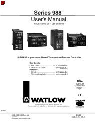
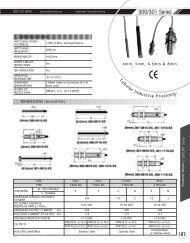
Customized linearization and Engineering units<br />
The accurate and versatile 40-point Customized linearization<br />
can be used to create any type of linearization curve for RTD,<br />
T/C, resistance and mV inputs. By combining Customized<br />
linearization with the use of Engineering units, the transmitters<br />
can be programmed to give a linear output corresponding<br />
to a specific measuring range expressed in the primary<br />
process value. The sensor characteristics are described by either<br />
up to 40 data pairs or 8 polynomials. Fig. 1a and 1b.<br />
Fig.1a<br />
Process<br />
value<br />
0-100 kPa<br />
Fig.1b<br />
mV<br />
50<br />
0<br />
Sensor<br />
Sensor<br />
100<br />
Sensor<br />
output<br />
0-50 mV<br />
kPa<br />
20<br />
mA<br />
4<br />
Transmitter<br />
System<br />
Transmitter<br />
output<br />
4-20 mA<br />
100<br />
Exemple of a system (sensor + transmitter) with an output linear to<br />
the process value, in spite of a non-linear sensor.<br />
kPa<br />
Sensor or System error correction<br />
<strong>IPAQ</strong>-L PLUS /<strong>IPAQ</strong>-LX PLUS offer two ways of improving the<br />
measurement with temperature sensors:<br />
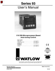
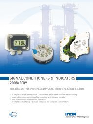
Sensor error correction - Known sensor errors compared<br />
to the standard curve, e.g. for a calibrated sensor, are entered,<br />
and the transmitter automatically corrects for the<br />
sensor errors. Fig. 2.<br />
Fig.2<br />
Sensor error correction<br />
Sensor output<br />
[Ω/mV]<br />
∆T1<br />
Tmin. T1<br />
∆T2<br />
T2 Tmax.<br />
Standard curve<br />
Sensor curve<br />
Temp.<br />
[°C/°F]<br />
Tmin and Tmax= End values<br />
of the measuring range.<br />
∆T1 and ∆T2=Deviations<br />
from Standard curve<br />
at T1 and T2.<br />
The transmitter<br />
compensates for the<br />
deviations and transforms<br />
the Sensor curve to a<br />
Standard curve<br />
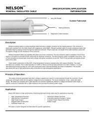
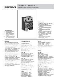
System error correction -This method is used to correct<br />
the system error (sensor + transmitter error) by exposing<br />
the sensor to one (one-point correction) or two (two-point<br />
correction) accurately measured temperatures (true tempera-<br />
tures).The true temperature(s) and the corresponding<br />
transmitter readings are entered, and the transmitter<br />
automatically corrects for the system errors. Fig. 3.<br />
Fig.3<br />
20<br />
12<br />
4<br />
Two-point System error correction<br />
Reading [mA]<br />
∆out1<br />
Tmin. T1<br />
∆out2<br />
T2 Tmax.<br />
True curve<br />
(corrected)<br />
System curve<br />
(before correction)<br />
Temp.<br />
[°C/°F]<br />
Tmin and Tmax= End values<br />
of the measuring range.<br />
∆out1 and ∆out2= Deviations<br />
from True curve at<br />
T1 and T2.<br />
The transmitter<br />
compensates for the<br />
deviations and transforms<br />
the System curve to a<br />
True curve<br />
SmartSense - Sensor isolation monitoring<br />
SmartSense continuously monitors the isolation resistance<br />
of thermocouples and 3-wire connected RTDs as well as<br />
the cabling between sensor and transmitter. The transmitter<br />
will react by forcing the output to a user defined level<br />
if the isolation is below a preset level. SmartSense requires<br />
an extra lead inside the thermocouple or RTD. Fig. 4.<br />
For detailed information, see section Theory and Facts.<br />
Sensor break monitoring<br />
<strong>IPAQ</strong>-L PLUS /<strong>IPAQ</strong>-LX PLUS monitor sensor break and force<br />
the output signal to a user defined level, when any sensor<br />
lead is broken or disconnected. The sensor break monitoring<br />
can be switched off. The monitoring is furnished with<br />
a pulsed excitation current. This eliminates the voltage drop<br />
in the lead wires (giving a measuring error), caused by a<br />
standard DC excitation current.<br />
Controlled output for instrument calibration<br />
<strong>IPAQ</strong>-L PLUS /<strong>IPAQ</strong>-LX PLUS can be set to automatically provide<br />
fixed or recurring output current regardless of the input<br />
signal. The time periods in recurring mode are<br />
selectable.