IPAQ-L Plus - INOR
IPAQ-L Plus - INOR
IPAQ-L Plus - INOR

Create successful ePaper yourself
Turn your PDF publications into a flip-book with our unique Google optimized e-Paper software.
High-performance Intelligent<br />
2-wire DIN Rail Transmitters<br />
<strong>IPAQ</strong>-L PLUS is a high-performance, universal and intelligent 2-wire<br />
DIN rail transmitter for temperature and other measurement<br />
applications.<br />
<strong>IPAQ</strong>-LX PLUS is the Intrinsic Safe version for use in Ex-applications.<br />
The outstanding combination of excellent specifications high<br />
functionality and simple configuration makes <strong>IPAQ</strong>-L PLUS and<br />
<strong>IPAQ</strong>-LX PLUS the obvious choice in demanding applications.<br />
The Windows based and user friendly software, IPRO 4, is used<br />
for transmitter configuration, documentation, monitoring and<br />
calibration purposes.<br />
Performance and design:<br />
Precision accuracy<br />
• Linearity 0.05 % for RTD.<br />
• Very low temperature influence.<br />
• Long-term stability 0.05 %/year.<br />
Fast response<br />
• Update time down to 170 ms, i.e. a measuring<br />
frequency of appr. 6 per second.<br />
Enhanced total system accuracy<br />
• Sensor error correction (for known sensor errors).<br />
• System error correction (against known temperatures).<br />
NAMUR-compliant<br />
• Output limitations and fail currents adjustable<br />
according to NAMUR recommendations.<br />
Smart Filter<br />
• Short response time combined with high noise immunity.<br />
Input-Output isolation 3750 VAC<br />
• Excellent filtering of voltage spikes and elimination<br />
of ground loops.<br />
High load capacity<br />
• Only 7.5 V voltage drop over the transmitter<br />
(<strong>IPAQ</strong>-L PLUS ) allows for high loads.<br />
Designed for harsh conditions<br />
• Excellent EMC performance.<br />
Space saving and simple mounting<br />
• Only 17.5 mm / 0.7 inch wide. Din Rail Mounting.<br />
5 year limited warranty.<br />
Functions:<br />
Input for RTDs, T/Cs, mV and resistance<br />
• Reduced inventory costs.<br />
• Simplified plant engineering.<br />
True on-line communication<br />
• Full access to all features while in operation.<br />
Configuration without external power<br />
• Editing or reading a configuration is possible also<br />
without external power supply.<br />
Display connection<br />
• Direct connection of an Inor digital display to the<br />
communication port.<br />
Efficient customized 40-point linearization<br />
• Any sensor characteristics can be matched.<br />
Sensor diagnostics<br />
• SmartSense detects low sensor isolation (essential<br />
for correct measurements).<br />
• Selectable sensor break action.<br />
Simplified loop check-up<br />
• The transmitter works as an accurate current<br />
generator with user defined action.<br />
On-screen indications and line recording<br />
• Valuable tools for temporary measurements.<br />
Improved QA with data storage<br />
• Vital information, such as TAG-No., maintenance<br />
record etc. can be stored in the nonvolatile memory.
<strong>IPAQ</strong>-L PLUS /LX PLUS<br />
Main features of <strong>IPAQ</strong>-L PLUS and <strong>IPAQ</strong>-LX PLUS<br />
Accuracy and stability<br />
<strong>IPAQ</strong>-L PLUS /<strong>IPAQ</strong>-LX PLUS are designed for applications<br />
with the highest demands on accuracy, also under severe<br />
operating conditions. To reach these demands, the following<br />
factors are essential:<br />
Low linearity and calibration errors -The combination of a<br />
high-efficient 40-point linearization and the use of quality<br />
components and precision calibration equipment reduce<br />
these errors to a minimum, e.g. ±0.05 % of span for RTD<br />
inputs.<br />
Low ambient temperature influence -Each transmitter in<br />
the <strong>IPAQ</strong> PLUS family is individually compensated at different<br />
temperatures within the operating range. This procedure<br />
minimizes the ambient influence to a minimum.<br />
High long-term stability -Internal “self calibration“, by<br />
means of continuous adjustment of important parameters<br />
after comparison with accurate built-in references, contributes<br />
to a stability better than ±0.05 %/year.<br />
Measurements with RTDs and other resistances<br />
<strong>IPAQ</strong>-L PLUS /<strong>IPAQ</strong>-LX PLUS accept inputs from standardized<br />
Platinum and Nickel RTDs like Pt10…Pt1000 acc. to IEC<br />
751 (α=0.00385), Pt100 acc. to JIS 1604 (α=0.003916) and<br />
Ni100/Ni1000 acc. to DIN 43760, as well as inputs from<br />
plain resistance sensors such as potentiometers.<br />
3- or 4-wire connection can be chosen.<br />
Measurements with thermocouples and plain voltage<br />
<strong>IPAQ</strong>-L PLUS /<strong>IPAQ</strong>-LX PLUS accept inputs from 11 types of<br />
standardized thermocouples as well as plain mV input.<br />
For T/C input, the CJC (Cold Junction Compensation) is<br />
fully automatic, by means of an accurate measurement of<br />
the terminal temperature. Alternatively, an external CJ<br />
temperature can be entered.<br />
Digital output for display<br />
Direct connection to external Inor display through the communication<br />
port. The information on the display is defined when<br />
programming the transmitter. Request display information.<br />
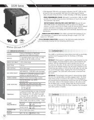
Customized linearization and Engineering units<br />
The accurate and versatile 40-point Customized linearization<br />
can be used to create any type of linearization curve for RTD,<br />
T/C, resistance and mV inputs. By combining Customized<br />
linearization with the use of Engineering units, the transmitters<br />
can be programmed to give a linear output corresponding<br />
to a specific measuring range expressed in the primary<br />
process value. The sensor characteristics are described by either<br />
up to 40 data pairs or 8 polynomials. Fig. 1a and 1b.<br />
Fig.1a<br />
Process<br />
value<br />
0-100 kPa<br />
Fig.1b<br />
mV<br />
50<br />
0<br />
Sensor<br />
Sensor<br />
100<br />
Sensor<br />
output<br />
0-50 mV<br />
kPa<br />
20<br />
mA<br />
4<br />
Transmitter<br />
System<br />
Transmitter<br />
output<br />
4-20 mA<br />
100<br />
Exemple of a system (sensor + transmitter) with an output linear to<br />
the process value, in spite of a non-linear sensor.<br />
kPa<br />
Sensor or System error correction<br />
<strong>IPAQ</strong>-L PLUS /<strong>IPAQ</strong>-LX PLUS offer two ways of improving the<br />
measurement with temperature sensors:<br />
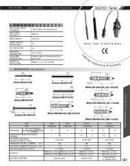
Sensor error correction - Known sensor errors compared<br />
to the standard curve, e.g. for a calibrated sensor, are entered,<br />
and the transmitter automatically corrects for the<br />
sensor errors. Fig. 2.<br />
Fig.2<br />
Sensor error correction<br />
Sensor output<br />
[Ω/mV]<br />
∆T1<br />
Tmin. T1<br />
∆T2<br />
T2 Tmax.<br />
Standard curve<br />
Sensor curve<br />
Temp.<br />
[°C/°F]<br />
Tmin and Tmax= End values<br />
of the measuring range.<br />
∆T1 and ∆T2=Deviations<br />
from Standard curve<br />
at T1 and T2.<br />
The transmitter<br />
compensates for the<br />
deviations and transforms<br />
the Sensor curve to a<br />
Standard curve<br />
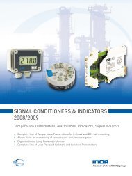
System error correction -This method is used to correct<br />
the system error (sensor + transmitter error) by exposing<br />
the sensor to one (one-point correction) or two (two-point<br />
correction) accurately measured temperatures (true tempera-<br />
tures).The true temperature(s) and the corresponding<br />
transmitter readings are entered, and the transmitter<br />
automatically corrects for the system errors. Fig. 3.<br />
Fig.3<br />
20<br />
12<br />
4<br />
Two-point System error correction<br />
Reading [mA]<br />
∆out1<br />
Tmin. T1<br />
∆out2<br />
T2 Tmax.<br />
True curve<br />
(corrected)<br />
System curve<br />
(before correction)<br />
Temp.<br />
[°C/°F]<br />
Tmin and Tmax= End values<br />
of the measuring range.<br />
∆out1 and ∆out2= Deviations<br />
from True curve at<br />
T1 and T2.<br />
The transmitter<br />
compensates for the<br />
deviations and transforms<br />
the System curve to a<br />
True curve<br />
SmartSense - Sensor isolation monitoring<br />
SmartSense continuously monitors the isolation resistance<br />
of thermocouples and 3-wire connected RTDs as well as<br />
the cabling between sensor and transmitter. The transmitter<br />
will react by forcing the output to a user defined level<br />
if the isolation is below a preset level. SmartSense requires<br />
an extra lead inside the thermocouple or RTD. Fig. 4.<br />
For detailed information, see section Theory and Facts.<br />
Sensor break monitoring<br />
<strong>IPAQ</strong>-L PLUS /<strong>IPAQ</strong>-LX PLUS monitor sensor break and force<br />
the output signal to a user defined level, when any sensor<br />
lead is broken or disconnected. The sensor break monitoring<br />
can be switched off. The monitoring is furnished with<br />
a pulsed excitation current. This eliminates the voltage drop<br />
in the lead wires (giving a measuring error), caused by a<br />
standard DC excitation current.<br />
Controlled output for instrument calibration<br />
<strong>IPAQ</strong>-L PLUS /<strong>IPAQ</strong>-LX PLUS can be set to automatically provide<br />
fixed or recurring output current regardless of the input<br />
signal. The time periods in recurring mode are<br />
selectable.
<strong>IPAQ</strong>-L PLUS /LX PLUS<br />
Smart Filter<br />
The Smart Filter detects the difference between fast signal<br />
changes and electrical noise, e.g. ripple and spikes, on the input.<br />
The smart filter offers a superior combination of very<br />
short response time for the input signal and high noise immunity.<br />
Adjustable dampening<br />
The dampening function can be used to dampen undesired instabilities<br />
on the input signal. The dampening time can be set<br />
between 0 and 10 seconds in intervals of 1 second. The dampening<br />
time is the time required, in addition to the update time,<br />
for the output to reach 90% of its final value after a step<br />
change has been applied to the input.<br />
NAMUR-compliant<br />
The output can be limited to high and low selectable values,<br />
i.e. 3.8 ≤ I ≤ 20.5 mA for NAMUR compliance. This function is<br />
overridden by the Sensor break monitoring and SmartSense.<br />
Power supply<br />
<strong>IPAQ</strong>-L PLUS /<strong>IPAQ</strong>-LX PLUS are loop-powered and will work on<br />
voltages down to 7.5 VDC (8.0 VDC for <strong>IPAQ</strong>-LX PLUS ), thus allowing<br />
for high loads in the current loop. Reversed polarity<br />
will not damage the transmitter. Fig. 5.<br />
Mounting<br />
<strong>IPAQ</strong>-L PLUS /<strong>IPAQ</strong>-LX PLUS are designed to fit on a standard<br />
35 mm rail according to DIN EN 50022.<br />
Warranty<br />
<strong>IPAQ</strong>-L PLUS /<strong>IPAQ</strong>-LX PLUS are covered by a 5 year limited warranty.<br />
IPRO 4 - The user friendly software for all transmitters<br />
of the <strong>IPAQ</strong> family<br />
IPRO 4, which is used with all <strong>IPAQ</strong>-transmitters, is the tool<br />
to utilize all the versatile functions of the <strong>IPAQ</strong>-L PLUS /<strong>IPAQ</strong>-<br />
LX PLUS such as:<br />
• Measurement configuration: Sensor type, range, sensor or<br />
system error correction, linearization, engineering units,<br />
output settings, filter activation, etc.<br />
• Monitoring of sensor status: Sensor break and sensor isolation<br />
(SmartSense).<br />
• On-screen real time presentation of measured values and<br />
output signal in the form of numericals, meters, bar graphs<br />
and line recorder.<br />
• Transmitter calibration: Field calibration in one or two<br />
points and basic calibration.<br />
• Documentation: Configuration files can be saved for future<br />
use and configuration protocols can easily be printed.<br />
The communication with the transmitter can be performed<br />
on line, i.e. with transmitter in operation.<br />
<strong>IPAQ</strong>-L PLUS /<strong>IPAQ</strong>-LX PLUS can also be configured without<br />
connecting a power supply.<br />
An isolated and Ex-approved communication cable is included<br />
in the software kit, IPRO-X.<br />
IPRO 4 is compatible with Windows 3.1, Windows 3.11, Windows<br />
95 and Windows NT Workstation 4.0. The program is<br />
menu-driven and easy to learn. On-line help is an effective<br />
tool for the user.<br />
<strong>IPAQ</strong>-L PLUS /<strong>IPAQ</strong>-LX PLUS Configuration scheme<br />
Input<br />
RTD<br />
Pt100 (IEC751, α=0.00385)<br />
Pt1000 (IEC751, α=0.00385)<br />
PtX 10 ≤ X ≤ 1000 (IEC751,<br />
α=0.00385)<br />
Ni100 (DIN 43760)<br />
Ni1000 (DIN 43760)<br />
D100 (Pt 100 acc.<br />
to JIS1604,α=0.003916)<br />
Thermocouple<br />
type AE<br />
W5%Rh-W26%Rh<br />
type B<br />
Pt30%Rh - Pt6%Rh<br />
type E NiCr-CuNi<br />
type J Fe-CuNi<br />
type K NiCr-Ni<br />
type L Fe-CuNi<br />
type N NiCrSi-NiSi<br />
type R Pt13%Rh-Pt<br />
type S Pt10%Rh-Pt<br />
type T Cu-CuNi<br />
type U Cu-CuNi<br />
Customer specific<br />
Resistance<br />
Span:<br />
10 Ω to 2000 Ω<br />
Voltage<br />
Span:<br />
2 mV to 500 mV<br />
Linearity<br />
Temperature linear<br />
Resistance linear<br />
Temperature linear<br />
Voltage linear<br />
Customized linearization<br />
Resistance linear<br />
Customized<br />
linearization<br />
Voltage linear<br />
Customized<br />
linearization<br />
Connections<br />
and additional<br />
functions<br />
3-wire connection<br />
4-wire connection<br />
3-wire connection<br />
+ SmartSense (Pt100/D100)<br />
Diff temperature (Pt100)<br />
Sensor break protection<br />
Sensor error correction<br />
System error correction<br />
Cold junction<br />
compensation (CJC)<br />
No CJC / External CJC<br />
CJC + SmartSense<br />
Sensor break protection<br />
Sensor error correction<br />
System error correction<br />
3-wire connection<br />
4-wire connection<br />
Engineering unit<br />
Sensor break<br />
protection<br />
Min/max correction<br />
Engineering unit<br />
Min/max correction<br />
Dampening<br />
Dampening time 0 - 10 s<br />
Output<br />
Current<br />
4 - 20 mA 20 - 4 mA Special<br />
Output limits
<strong>IPAQ</strong>-L PLUS /LX PLUS<br />
Specifications<br />
Input<br />
RTD’s and Resistance<br />
Pt100 (IEC751, α=0.00385) 3-, 4-wire connection -200 to +1000 °C / -328 to +1832 °F<br />
Pt1000 (IEC751, α=0.00385) 3-, 4-wire connection -200 to +200 °C / -328 to +392 °F<br />
PtX 10 ≤ X ≤ 1000 (IEC751, α=0.00385) 3-, 4-wire connection Upper range depending on X-value<br />
Ni100 (DIN 43760) 3-, 4-wire connection -60 to+250 °C / -76 to +482 °F<br />
Ni1000 (DIN 43760) 3-, 4-wire connection -60 to +150 °C / -76 to +302 °F<br />
D100 (Pt 100 acc.to JIS1604, α=0.003916) 3-, 4-wire connection -200 to +1000 °C / -328 to +1832 °F<br />
Potentiometer/resistance 3-, 4-wire connection 0 to 2000 Ω<br />
Sensor current ~ 0.4 mA<br />
Maximum sensor wire resistance<br />
25 Ω/wire<br />
Thermocouples and Voltage<br />
T/C Type: AE, B, E, J, K, L, N, R, S, T, U Ranges according to users manual<br />
Voltage input<br />
-10 to +500 mV<br />
Input impedance<br />
>10 MΩ<br />
Maximum sensor wire resistance<br />
500 Ω (total loop)<br />
Monitoring<br />
Sensor break monitoring User definable output 3.5 to 22.8 mA 1)<br />
SmartSense, sensor isolation monitoring User definable output 3.5 to 22.8 mA 1)<br />
Adjustments<br />
Zero adjustment All inputs Any value within range limits<br />
Minimum spans Pt100, Pt1000, Ni100, Ni1000 10 °C / 18 °F<br />
Potentiometer<br />
10 Ω<br />
T/C, mV<br />
2 mV<br />
Output<br />
Straight,reversed or any intermediate value<br />
4-20/20-4 mA<br />
Resolution 5 µA<br />
Minimum output signal Adjustable ≥3.5 mA<br />
Maximum output signal Adjustable ≤22.8 mA<br />
Permissible load, see fig.5 <strong>IPAQ</strong>-L PLUS 715 Ω @ 24 VDC, 23 mA<br />
<strong>IPAQ</strong>-LX PLUS 695 Ω @ 24 VDC, 23 mA 2)<br />
Temperature<br />
Ambient, storage -20 to +70 °C / -4 to +158 °F<br />
Ambient, operation <strong>IPAQ</strong>-L PLUS -20 to +70 °C / -4 to +158 °F<br />
<strong>IPAQ</strong>-LX PLUS<br />
Acc. to Ex-approval (pending)<br />
General data<br />
Adjustable dampening time<br />
0 to 10 s<br />
Update time ~ 170 ms 3)<br />
Isolation In - Out<br />
3750 VAC, 1 min<br />
Humidity (non-condensing)<br />
0 to 95 %RH<br />
Intrinsic safety <strong>IPAQ</strong>-LX PLUS , Cenelec Approval pending<br />
FM<br />
Approval pending<br />
Power supply, polarity protected<br />
Supply voltage (transmitter terminals) <strong>IPAQ</strong>-L PLUS 7.5 to 36 VDC 2-wire<br />
<strong>IPAQ</strong>-LX PLUS<br />
8.0 to 30 VDC 2) 2-wire<br />
Permissible ripple<br />
4 V p-p @ 50/60 Hz<br />
1)<br />
Independent of output limitation<br />
2)<br />
Preliminary data<br />
3)<br />
~300 ms with Sensor Break Monitoring activated
<strong>IPAQ</strong>-L PLUS /LX PLUS<br />
Accuracy<br />
Linearity RTD Potentiometer, mV ±0.05 % 1)<br />
1)<br />
Of input span<br />
2)<br />
With equal wire resistance<br />
3)<br />
If zero-deflection > 100% of input span:<br />
add 0.125% of input span/25 °C or 0.14%<br />
of input span/50 °F per 100% zero-deflection<br />
4)<br />
Reference temperature 23 °C/73°F<br />
T/C ±0.1 % 1)<br />
Calibration RTD Max. of ±0.1 °C / ±0.2 °F or ±0.05 % 1)<br />
Potentiometer Max. of ±0.1 Ω or ±0.05 % 1)<br />
mV, T/C Max. of ±20 µV or ±0.05 % 1)<br />
Cold Junction Compensation (CJC) T/C ±0.5 °C / ±0.9 °F<br />
Temperature influence 4) All inputs Max. of ±0.125 °C/25 °C or ±0.125%/25 °C<br />
Max. of ±0.25 °F/50 °F or ± 0.14%/50 °F<br />
Temperature influence CJC 4) T/C ±0.5 °C/25 °C / ±1.0 °F/50 °F<br />
Instrument calibration output 4-20 mA ±4.5 µA<br />
Sensor wire resistance influence RTD, Potentiometer, 3-wire Negligible 2)<br />
RTD, Potentiometer, 4-wire Negligible<br />
mV, T/C<br />
Negligible<br />
Load influence<br />
Negligible<br />
Power supply influence<br />
Negligible<br />
RFI influence, 0.15-1000 MHz, 10 V or V/m<br />
±0.3 % 1) (typical)<br />
Long-term stability<br />
Housing<br />
±0.05 % 1) /year<br />
Material / Flammability (UL)<br />
PC + Glass fibre / VO<br />
Mounting<br />
Rail acc. to DIN EN 50022, 35 mm.<br />
Connection Single/stranded wires ≤1.5 mm 2 , AWG 16<br />
Weight<br />
70 g<br />
Protection, housing / terminals IP 20 / IP 20<br />
The User Instructions must be read prior to adjustment and/or installation.<br />
1) 3)<br />
1) 3)<br />
Accuracy examples<br />
Applications Partial accuracies (°C) Total<br />
statistical accuracy<br />
Linearity Calibration CJC Temperature Temperature °C 5) % of span<br />
influence influence CJC<br />
Pt100, 0-200 °C, TAmb = 25°C ±0.1 ± 0.1 _ ± 0.02 _ ± 0.14 ± 0.07<br />
Pt100, 0-200 °C, TAmb = 50°C ±0.1 ± 0.1 _ ± 0.27 _ ± 0.30 ± 0.15<br />
T/C K, 0-600 °C, TAmb = 25°C ±0.6 ± 0.3 ± 0.5 ± 0.06 ± 0.04 ± 0.84 ± 0.14<br />
T/C K, 0-600 °C, TAmb = 50°C ±0.6 ± 0.3 ± 0.5 ± 0.81 ± 0.54 ± 1.28 ± 0.21<br />
Reference temperature: TAmb = 23 °C<br />
5)<br />
Total statistical accuracy (∆Tot) is calculated as the<br />
”Root Mean Square” of the partial accuracies (∆1...∆n)<br />
∆Tot = ∆1 2 + ∆2 2 +.......+ ∆n 2
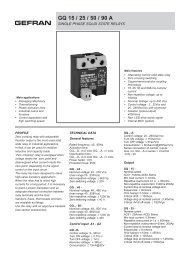
INPUTS<br />
Pt100, Pt1000, Ni100, Ni1000, PtX, D100<br />
4-wire connection<br />
3-wire connection<br />
RTD<br />
Pt100 D100<br />
Pt100<br />
3-wire connection Diff temperature T 1<br />
>T 2<br />
Potentiometer<br />
*SmartSense lead<br />
Voltage<br />
4-wire connection 3-wire connection mV<br />
T 2<br />
T 1<br />
Thermocouple<br />
AE,B,E,J,K,L,N,R,S,T,U<br />
or customer specific<br />
4-20 mA Output<br />
Power<br />
Supply + -<br />
OUTPUT<br />
R Load<br />
*Only <strong>IPAQ</strong>-L PLUS<br />
Connections<br />
Power supply<br />
+ -<br />
- *<br />
Test<br />
(mA)<br />
+<br />
78<br />
56<br />
7 -Test<br />
4 +Out- 5<br />
mV<br />
- +<br />
1 2<br />
3 4<br />
12<br />
34<br />
Input<br />
- +<br />
R LOAD<br />
I OUT<br />
PC<br />
Connection<br />
- +<br />
*SmartSense lead<br />
Dimensions<br />
17.5/0.69<br />
58/2.28<br />
35/<br />
45/ 90/<br />
1.38<br />
1.77 3.54<br />
mm / inches<br />
<strong>IPAQ</strong>-L PLUS /LX PLUS Item Part No.<br />
SmartSense Output load diagram Ordering table<br />
Fig.4<br />
* *<br />
Pt100/D100 T/C<br />
* SmartSense lead<br />
Fig.5<br />
Permissible RLoad at 23 mA output<br />
RLoad (Ω)<br />
1600<br />
1200<br />
800<br />
400<br />
0<br />
4<br />
8<br />
12<br />
<strong>IPAQ</strong>-LX PLUS<br />
16 20 24 28 32 36<br />
Supply voltage U (VDC)<br />
R Load<br />
=(U-7.5)/0.023 (<strong>IPAQ</strong>-L PLUS )<br />
R Load<br />
=(U-8.0)/0.023 (<strong>IPAQ</strong>-LX PLUS )<br />
<strong>IPAQ</strong>-L PLUS<br />
Transmitter<br />
<strong>IPAQ</strong>-L PLUS<br />
70IPLP0001<br />
<strong>IPAQ</strong>-LX PLUS (Cenelec) 70IPLPX001<br />
<strong>IPAQ</strong>-LX PLUS (FM) 70IPLPX101<br />
Options<br />
Configuration<br />
70CAL00001<br />
Configuration with 5-point<br />
calibration certificate 70CAL00051<br />
Software and cable<br />
IPRO-X (IPRO with cable) 70IPRX0001<br />
Software IPRO upgrade 70IPRS0001