Create successful ePaper yourself
Turn your PDF publications into a flip-book with our unique Google optimized e-Paper software.
<strong>TTC</strong> <strong>in</strong> <strong>CMS</strong><br />
João Varela<br />
LIP-Lisbon & CERN<br />
CERN, 29 June 2001<br />
<strong>TTC</strong> Workshop
<strong>TTC</strong>mi<br />
Partition<br />
Control<br />
<strong>TTC</strong>vi FMM<br />
<strong>TTC</strong>rx<br />
Trigger Control Architecture<br />
FrontEnd<br />
Global Trigger Control<br />
Partition<br />
Control<br />
<strong>TTC</strong>vi FMM<br />
<strong>TTC</strong>rx<br />
FrontEnd<br />
Partition<br />
Control<br />
<strong>TTC</strong>vi FMM<br />
<strong>TTC</strong>rx<br />
FrontEnd<br />
DAQ Event<br />
Manager
From Global Trigger<br />
From <strong>TTC</strong> Mach<strong>in</strong>e Interface<br />
L1A<br />
Orbit<br />
LHC Clock<br />
Multi-Partition Trigger Control<br />
TTS<br />
Trigger Rules<br />
FE Buffer Emulation<br />
Trigger<br />
Inhibit<br />
Fast Control Generator<br />
L1A<br />
Drives <strong>TTC</strong> network<br />
To Sub-detector Partitions<br />
BC0<br />
L1 Reset<br />
Test Enable<br />
Start/Stop<br />
32 Partitions<br />
Calibration/Test control<br />
Generate calibration/test trigger<br />
sequences<br />
Ready/<br />
Busy<br />
Test Trigger<br />
Fast Monitor<strong>in</strong>g<br />
Fast monitor<strong>in</strong>g programmable logic<br />
Error Warn<strong>in</strong>g Out of<br />
Overflow Sync<br />
From Sub-detector Partitions<br />
Orbit<br />
Trigger Inhibit<br />
FM status<br />
Dead Time<br />
Monitor<br />
Start/<br />
Stop<br />
VME<br />
Control<br />
From/To Run Control<br />
Allows Subdetector Partitions<br />
or Partition-Groups to run<br />
<strong>in</strong>dependently with complete<br />
functionality<br />
Provides <strong>in</strong>dependent<br />
calibration or physics triggers<br />
to different Partition-Groups<br />
In normal data tak<strong>in</strong>g all<br />
subsystems are <strong>in</strong>cluded <strong>in</strong><br />
one group<br />
Reconfiguration achieved by<br />
software programm<strong>in</strong>g
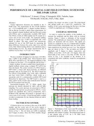
FARADAY<br />
CAGE<br />
(BA3-Prevess<strong>in</strong>)<br />
LHC<br />
EXPERIMENT<br />
AREA<br />
(Count<strong>in</strong>g Room)<br />
<strong>TTC</strong>vi/<strong>TTC</strong>ex<br />
CRATE<br />
(N= 32, 20, 10)<br />
(Multimode<br />
fibers<br />
-2dB max)<br />
CPU<br />
Left<br />
Pre-<br />
Shower<br />
2 Crates<br />
LHC Clock 40.079MHz<br />
PREVESSIN CONTROL ROOM<br />
ENCODER<br />
LHC Orbit<br />
J=10ps RMS<br />
11.246 kHz SYNC<br />
SPS Orbit<br />
MODULATOR<br />
43.375 kHz<br />
LASER<br />
LHC Clock<br />
and Orbit<br />
Other dest<strong>in</strong>ations<br />
B-go<br />
1m Lemo Cables<br />
<strong>TTC</strong>vi<br />
<strong>TTC</strong>ex<br />
<strong>TTC</strong>vi<br />
L1A<br />
Fast cmds<br />
1:N Optical Splitter<br />
Left<br />
Endcap<br />
12 Crates<br />
<strong>TTC</strong>vi<br />
<strong>TTC</strong>ex<br />
<strong>TTC</strong>vi<br />
Left<br />
Barrel<br />
18 Crates<br />
1:32 Optical Splitter<br />
<strong>TTC</strong>mi<br />
<strong>TTC</strong>cf<br />
<strong>TTC</strong>vi<br />
<strong>TTC</strong>ex<br />
<strong>TTC</strong>vi<br />
Right<br />
Barrel<br />
18 Crates<br />
J=10ps RMS<br />
Right<br />
Endcap<br />
12 Crates<br />
LHCrx<br />
LVL1<br />
Cal<br />
Right<br />
Pre<br />
Shower<br />
2 Crates<br />
(S<strong>in</strong>glemode fibers)<br />
(-17dB max)<br />
LVL1<br />
Muon<br />
Global Trigger<br />
Trigger Control System<br />
J=10ps RMS<br />
Subdetector <strong>TTC</strong><br />
partitions<br />
<strong>TTC</strong> distribution system:<br />
Two-time division multiplexed channels<br />
Optical passive network<br />
Channel A: L1A signal (40 Mbit/s)<br />
Channel B: Fast commands (40 Mbit/s)<br />
Sub-detectors <strong>TTC</strong> master crate:<br />
<strong>TTC</strong>vi module: gets L1A and B-Go signals;<br />
VME <strong>in</strong>terface (programm<strong>in</strong>g of cmds)<br />
<strong>TTC</strong>ex module: encoder and transmitter
Level 1 Accept (L1A)<br />
Fast Control Signals<br />
● Transmitted every trigger (<strong>TTC</strong> Channel A)<br />
● Event Identifier: Event Number , Bunch Number, Orbit Number, Trigger Type<br />
Bunch Cross<strong>in</strong>g Zero (BC0)<br />
● Periodic command synchronous to LHC Orbit signal (~ 11 kHz)<br />
● Synchronization of trigger data, Bunch Counter Reset<br />
Fast Reset<br />
● L1 Reset: Re-synchronization of event ID and readout buffers<br />
● Hard Reset: Partial reset of readout electronics
Calibration and Test Modes<br />
1) Sub-detectors <strong>in</strong> standalone mode:<br />
Test and calibration sequences are generated locally<br />
Data is captured with the sub-detector DAQ<br />
2) Sub-detectors <strong>in</strong> DAQ partition mode:<br />
Trigger Control sends test and calibration triggers to a partition-group<br />
Data is collected by the central DAQ<br />
3) Periodic test and calibration triggers dur<strong>in</strong>g a Physics Run:<br />
Test triggers sequences are issued centrally and distributed to all partitions<br />
Calibration/test triggers are issued at pre-programmed cycles <strong>in</strong> the LHC orbit<br />
Data is collected by the central DAQ<br />
4) Local test and calibration triggers dur<strong>in</strong>g a Physics Run:<br />
The sub-systems perform test, calibration or monitor<strong>in</strong>g activities dur<strong>in</strong>g Private Gaps<br />
and Private Orbits
Calibration Control Signals<br />
Fast Control Signal <strong>TTC</strong> Command Type Comments<br />
Test Enable Channel-B Broadcast Broadcast command sent a<br />
fixed time before a test or<br />
calibration trigger.<br />
Private Gap Channel-B Broadcast Broadcast command mark<strong>in</strong>g<br />
the next Gap for private use by<br />
the sub-detectors<br />
Private Orbit Channel-B Broadcast Broadcast command mark<strong>in</strong>g<br />
the next Orbit for private use<br />
by the sub-detectors<br />
Calibration Request Signal: sub-detectors may use the Fast Monitor<strong>in</strong>g system to send<br />
Calibration Request signals.
Trigger Control<br />
Inhibit L1A<br />
Sub-System<br />
Clock40Des1 (<strong>TTC</strong>rx)<br />
BrcstStr1 (<strong>TTC</strong>rx)<br />
Brcst (<strong>TTC</strong>rx)<br />
Test Signal<br />
Test data <strong>in</strong> pipel<strong>in</strong>es<br />
Test/Calibration Sequence<br />
Broadcast<br />
TestEnable<br />
= =<br />
L1A stoped<br />
Brcst Cmd<br />
Received<br />
t1<br />
150 bx (programmable)<br />
TestEnable<br />
decoded<br />
Generate<br />
Test Pulse<br />
t1 = delay on TestEnable command; adjusted <strong>in</strong> subdetector <strong>TTC</strong>vi's<br />
Send L1A to capture<br />
test data<br />
=<br />
Enable normal L1A<br />
L1A readout<br />
sequence<br />
Normal L1As<br />
restart
Fast Monitor<strong>in</strong>g Signals<br />
Signals received from Sub-detector Partitions and DAQ Event Manager<br />
● Ready<br />
The Partition is ready to receive triggers<br />
⇒ Allow L1As<br />
● Busy<br />
The Partition is not ready to take data and can’t accept L1A’s<br />
⇒ Inhibit L1As<br />
● Warn<strong>in</strong>g Overflow<br />
The Partition buffers are close to overflow and L1A rate should be reduced<br />
⇒ Reduce L1As<br />
● Out of Sync<br />
Loss of synchronization <strong>in</strong> readout or trigger Partition<br />
⇒ L1 Reset<br />
● Error<br />
The Partition is <strong>in</strong> error and needs a reset<br />
⇒ Hard Reset<br />
HARDWARE<br />
SIGNALS<br />
FAST<br />
MESSAGES
Trigger Throttl<strong>in</strong>g<br />
Front-end buffers may overflow due to statistic fluctuations <strong>in</strong> trigger rate and event size.<br />
Front-End Buffers Emulation<br />
Front-end pipel<strong>in</strong>e-derandomizers are emulated centrally<br />
L1 trigger is <strong>in</strong>hibited if an overflow condition is detected<br />
Trigger Rules<br />
No more than n L1A per X ns (dead time less than 1%)<br />
Fast Monitor<strong>in</strong>g<br />
Fast feedback signal Warn<strong>in</strong>g Overflow<br />
Local Buffer Monitor<strong>in</strong>g<br />
Above buffer warn<strong>in</strong>g level store 'empty events'<br />
Data<br />
Error<br />
MUX<br />
sel<br />
Input<br />
FIFO<br />
Almost Full<br />
Output
Synchronization Losses<br />
Identification of Sync Loss conditions that will require a L1 Reset:<br />
<strong>in</strong> readout systems<br />
- buffer overflow<br />
- mismatch between event ID's at any level of data concentration (FED, DCC, RU)<br />
- mismatch between number of events received and number of L1A received<br />
- mismatch between <strong>in</strong>ternal BC counter content and BC0 command<br />
(checked every orbit)<br />
<strong>in</strong> trigger systems<br />
mismatch between <strong>in</strong>ternal BC counter content and BC0 command<br />
(checked every orbit)
Trigger Control<br />
Inhibit L1A<br />
Readout<br />
Sub-System<br />
Clock40Des1 (<strong>TTC</strong>rx)<br />
BrcstStr1 (<strong>TTC</strong>rx)<br />
Brcst (<strong>TTC</strong>rx)<br />
Busy (FM)<br />
Ready (FM)<br />
t1<br />
Broadcast<br />
Reset<br />
= =<br />
L1A stoped<br />
Brcst Cmd<br />
Received<br />
Fast Reset Sequence<br />
t2<br />
Broadcast<br />
Event Counter Reset<br />
=<br />
Reset<br />
decoded<br />
Reset<br />
DAQ buffers<br />
t1 = time needed to empty DAQ buffers <strong>in</strong> subsystems<br />
t2 = time needed to transmit a broadcast command to subsystems<br />
Broadcast<br />
Bunch Counter Reset<br />
at next Orbit<br />
Evt Counter<br />
set to zero<br />
Enable L1A<br />
=<br />
Bunch Counter<br />
set to zero<br />
L1As restart
Project Status<br />
- Conceptual design is be<strong>in</strong>g f<strong>in</strong>alized<br />
- Interfaces and functional specs of Trigger Control ready up<br />
to end 2001<br />
- Detailed eng<strong>in</strong>eer<strong>in</strong>g design will start <strong>in</strong> 2002
Functionality of <strong>TTC</strong>rx<br />
- Functionality of <strong>TTC</strong>rx is well adapted to <strong>CMS</strong> architecture<br />
- Clock jitter 150 ps p/p is a po<strong>in</strong>t of concern when used as<br />
master clock for high speed serial l<strong>in</strong>ks<br />
- <strong>CMS</strong> favors a re-design <strong>in</strong> submicron technology<br />
- <strong>CMS</strong> prefers a QFP packag<strong>in</strong>g
General comments<br />
Functionality of <strong>TTC</strong>vi<br />
Present <strong>TTC</strong>vi seems well adapted to small test systems<br />
Functionality of f<strong>in</strong>al <strong>TTC</strong>vi should not be frozen now<br />
<strong>CMS</strong> prefers to wait one year for a better understand<strong>in</strong>g of<br />
the overall architecture and for more practical experience<br />
with test systems
Prelim<strong>in</strong>ary detailed comments on <strong>TTC</strong>vi<br />
B-Channel<br />
- Addition of 12 external B-Go signals to the present 4, allow<strong>in</strong>g 16 different<br />
command types. Each new channel is associated to a s<strong>in</strong>gle 8-bit register were a<br />
short-format broadcast command code can be stored.<br />
- Priority scheme not needed. Tim<strong>in</strong>g of B-commands is externally controlled (Bcommands<br />
are not allowed to overlap) <strong>in</strong> order to guarantee synchronicity of Bchannel.<br />
- Programmable B-Go delay between external B-Go signal and actual command<br />
transmission is needed.<br />
- Prescal<strong>in</strong>g factor on B-Go channels, such that <strong>in</strong> synchronous repetitive mode a<br />
pre-loaded command is transmitted every N orbits.
Internal Generation of L1A<br />
Generation of L1A synchronous with the Orbit signal (at programmable bunch<br />
cross<strong>in</strong>g number). Associated with this feature a Delay and a Prescal<strong>in</strong>g factor should<br />
be def<strong>in</strong>ed.<br />
Transmission of Trigger Type<br />
Addition of the possibility of transmitt<strong>in</strong>g after L1A, through B-channel, the Trigger<br />
Type only (The present <strong>TTC</strong>vi version has an option that allows to transmit after L1A<br />
the Trigger Type and the Event Number).<br />
Input Levels<br />
TTL and LVDS levels are more suitable than the present NIM and ECL levels
SUB-SYSTEM<br />
Pixels 100<br />
Tracker 610<br />
ECAL 1450<br />
Preshower 140<br />
HCAL 1093<br />
DT 400<br />
Prelim<strong>in</strong>ary <strong>CMS</strong> <strong>TTC</strong> Numbers<br />
Quantity Schedule<br />
2001 - 10 for R&D<br />
2002 - 10 for R&D<br />
2003 - 10 for R&D<br />
2004 - 70 for production<br />
Optical Splitt<strong>in</strong>g<br />
1:N Fiber length Quantity Schedule<br />
1 x 1:24<br />
1 x 1:18 10-20 m 5<br />
2 <strong>in</strong> 2002<br />
2 <strong>in</strong> 2004<br />
1 <strong>in</strong> 2006<br />
2002 - 50<br />
2003 - 50<br />
2004 - 510 4 x 1:150 10-20 m Not yet known Not yet known<br />
July 2001 5 pcs;<br />
Jan. 2002 25 pcs;<br />
Dec. 2002 50 pcs;<br />
2003 1370 pcs.<br />
2 x 1:18 (EB)<br />
2 x 1:12 (EE) 10-20 m 8<br />
2001 few pieces;<br />
2002 few 10s;<br />
2003-2004 rest 10-20 m 5<br />
50 chips and 15 <strong>TTC</strong>Rx<br />
test boards now<br />
2Q 2002 - 1028<br />
1:18 or 1:36 for<br />
90 m fibers ~90 m<br />
2001 - 10<br />
early 2002 - the rest ~90 m 5<br />
CSC 100 2001 - 15 pcs 1:30 ~90 m 3<br />
RPC 2710<br />
TRIGGER/DAQ 250<br />
TOTAL<br />
6850<br />
<strong>TTC</strong>rx<br />
2001 - 20<br />
2002 - 1000<br />
2003 - 1000<br />
2004 - 690<br />
77 optical<br />
couplers ~90 m<br />
2002 - 100<br />
2003 - 150 8 x 1:32 10-20 m 11<br />
2001 - 130<br />
2002 - 2770<br />
2003 - 2680<br />
2004 - 1270<br />
Optical Couplers and<br />
fibers<br />
2001 1pc;<br />
2002 1 pc;<br />
2003 2 pcs;<br />
2004 4 pcs<br />
2001 1 pc;<br />
2002 1 pc;<br />
2003-2004 3 pcs.<br />
2001 - 2<br />
2002 - 1<br />
2 <strong>TTC</strong>vi<br />
2 <strong>TTC</strong>ex<br />
6 <strong>TTC</strong>tx 2002<br />
>32<br />
<strong>TTC</strong>vi/<strong>TTC</strong>ex
Experience with <strong>TTC</strong> System <strong>in</strong> <strong>CMS</strong><br />
SUB-SYSTEM<br />
Prototypes<br />
with <strong>TTC</strong>rx<br />
<strong>TTC</strong> systems<br />
<strong>in</strong>stalled<br />
<strong>TTC</strong> systems <strong>in</strong><br />
test beam<br />
Pixels 1 0 0<br />
Tracker 2 5 1<br />
ECAL 2 1 0<br />
Preshower 0 0 0<br />
HCAL<br />
DT 0 1 0<br />
CSC 1 1 0<br />
RPC 3 1 1
CONCLUSIONS<br />
- <strong>TTC</strong> system is extensively used by <strong>CMS</strong><br />
- Functionality of <strong>TTC</strong>rx is well adapted to <strong>CMS</strong> architecture<br />
- <strong>CMS</strong> needs about 7000 <strong>TTC</strong>rx<br />
- <strong>CMS</strong> prefers to wait one year to def<strong>in</strong>e the f<strong>in</strong>al<br />
specification of <strong>TTC</strong>vi