PURE WATER - Watts Water Technologies, Inc.
PURE WATER - Watts Water Technologies, Inc.
PURE WATER - Watts Water Technologies, Inc.

You also want an ePaper? Increase the reach of your titles
YUMPU automatically turns print PDFs into web optimized ePapers that Google loves.
Installation, Operation<br />
and Maintenance Manual<br />
Zero Waste Reverse Osmosis System<br />
Model PWRO4ZRO<br />
<strong>PURE</strong> <strong>WATER</strong><br />
Important<br />
Please read the entire manual before proceeding with the<br />
installation and startup. Your failure to follow any attached<br />
instructions or operating parameters may lead to the product’s<br />
failure.<br />
Save manual for future reference.<br />
IOM-WQ-PWRO4ZRO<br />
PWRO4ZRO<br />
System tested and certified by NSF International<br />
against NSF/ANSI Standard 58 for the reduction<br />
of the claims specified on the performance data<br />
sheet.<br />
Table of Contents<br />
Pages<br />
Operational Parameters. ..................................3<br />
Contents of Reverse Osmosis System. .......................3<br />
Tools Recommended For Installation .........................3<br />
Drill a Hole for the Faucet in a Porcelain Sink ...................3<br />
Punch a Hole for the Faucet in a Stainless Steel Sink. ............3<br />
How to use Quick-Connect Fittings ..........................4<br />
<strong>Watts</strong> Top Mount Faucet Installation .........................5<br />
Adapt-A-Valve Installation ...............................5<br />
Reverse Osmosis Module Mounting .........................5<br />
Green Tube Connection. ..................................6<br />
Black Tube Connection ...................................6<br />
Check Air Pressure in the Tank .............................6<br />
Tank Ball Valve Installation .................................6<br />
Final Filter Installation. ....................................6<br />
Start up Instructions .....................................7<br />
6-Month Maintenance ....................................8<br />
Annual Maintenance .....................................8<br />
Membrane Replacement ..................................9<br />
Procedure for Extended Non-Use (More than 2 months) ..........9<br />
Troubleshooting. .......................................10<br />
Parts List .............................................11<br />
Arsenic Facts. .........................................12<br />
Service Record ........................................13<br />
Limited Warranty .......................................16<br />
Note: Do not use with water that is microbiologically unsafe or<br />
of unknown quality without adequate disinfection before or after<br />
the system. Systems certified for cyst reduction may be used<br />
on disinfected waters that may contain filterable cysts.
Introduction<br />
Thank you for your purchase of a state of the art <strong>Watts</strong> Reverse<br />
Osmosis (RO) water treatment system. <strong>Water</strong> quality concerns are<br />
becoming more of a focus for the public. You may have heard about<br />
contaminants in the drinking water, such as Arsenic, Chromium,<br />
Cryptosporidium or Giardia. There may also be some local water<br />
issues such as high levels of Lead and Copper. This <strong>Watts</strong> water<br />
treatment system has been designed and tested to provide you with<br />
high quality drinking water for years to come. The following is a brief<br />
overview of the system.<br />
Your Reverse Osmosis System:<br />
Osmosis is the process of water passing through a semi-permeable<br />
membrane in order to balance the concentration of contaminants<br />
on each side of the membrane. A semi-permeable membrane is a<br />
barrier that will pass some particles like clean drinking water, but not<br />
other particles like arsenic and lead.<br />
Reverse osmosis uses a semi-permeable membrane; however, by<br />
applying pressure across the membrane, it concentrates contaminants<br />
(like a strainer) on one side of the membrane, producing crystal<br />
clear water on the other. This is why RO systems produce both clean<br />
drinking water and waste water that is flushed from the system. This<br />
reverse osmosis system also utilizes carbon block filtration technology<br />
and can, therefore, provide a higher quality drinking water than<br />
carbon filtration systems alone.<br />
Your system is a 4-Stage RO which is based upon separate treatment<br />
segments within the one complete water filtration system.<br />
These stages are as follows:<br />
Stage 1 – Sediment filter, recommended change 6 months.<br />
The first stage of your RO system is a five-micron sediment<br />
filter that traps sediment and other particulate matter<br />
like dirt, silt and rust which affect the taste and appearance<br />
of your water.<br />
Stage 2 – Carbon filter, recommended change 6 months.<br />
The second stage contains a five-micron carbon block<br />
filter. This helps ensure that chlorine and other materials<br />
that cause bad taste and odor are greatly reduced.<br />
Stage 3 - Membrane, recommended change 2-5 years.<br />
Stage 3 is the heart of the reverse osmosis system, the<br />
RO membrane. This semi-permeable membrane will effectively<br />
take out TDS, Sodium and heavy metals such as<br />
arsenic, copper, and lead, as well as cysts, such as Giardia<br />
and cryptosporidium. Because the process of making<br />
this high quality drinking water takes time, your RO water<br />
treatment system is equipped with a storage tank.<br />
Stage 4 - Carbon in-line filter, recommend change 6 - 12<br />
months.<br />
The final stage is an in-line granular activated carbon<br />
(GAC) filter. This filter is used after the water storage tank,<br />
and is used as a final polishing filter.<br />
Note: Filter & Membrane life may vary based upon local water<br />
conditions and/or use patterns.<br />
System Maintenance<br />
Just because you can not taste it, does not mean that it is not there.<br />
Contaminants such as lead, chromium and arsenic (to name a few)<br />
are undetectable to the taste. Additionally, over time if you do not<br />
replace the filter element, other bad tastes and odors will be apparent<br />
in your drinking water.<br />
This is why it is important to change out your filter at the recommended<br />
intervals as indicated in this system manual. When replacing<br />
the filter elements, pay special attention to any cleaning instructions.<br />
Should you have any further questions please refer to our website<br />
at www.watts.com or call our customer service department at<br />
1-800-244-1299.<br />
With proper installation and maintenance, this system will provide<br />
you with high quality water for years to come. All of <strong>Watts</strong> water<br />
enhancement products are rigorously tested by independent laboratories<br />
for safety and reliability. If you have any questions or concerns,<br />
please contact our Customer Service department at 1-800-244-<br />
1299 or refer to our on-line troubleshooting at www.watts.com.<br />
2
Operational Parameters<br />
Do not use with water that is microbiologically unsafe or of<br />
unknown quality without adequate disinfection before or after<br />
the system. System is intended to be installed on the cold water<br />
line only.<br />
Operating Temperatures Maximum 100°F (37.8°C) Minimum 40°F (4.4°C)<br />
Operating Pressure<br />
Maximum 85psi<br />
Minimum 40psi<br />
(6.0 kg/cm2)<br />
(2.80 kg/cm2)<br />
pH Parameters Maximum 11 Minimum 2<br />
Iron<br />
Maximum 0.2 ppm<br />
TDS (Total Dissolved Solids) < 1800 ppm<br />
Turbidity<br />
< 5NTU<br />
Hardness: Recommended hardness not to exceed 10 grains per<br />
gallon, or 170ppm. System will operate with hardness over 10 grains<br />
but the membrane life may be shortened. Addition of a water softener<br />
may lengthen the membrane life.<br />
<strong>Water</strong> Pressure: The operating water pressure in your home should<br />
be tested over a 24 hour period to attain the maximum pressure.<br />
If the incoming water pressure is above 85psi a pressure regulator<br />
is recommended and if over 100psi then a pressure regulator is<br />
required.<br />
Copper Tubing: Reverse Osmosis water should not be run through<br />
copper tubing as the purity of the water will leach copper causing<br />
an objectional taste in water and pin holes may form in the tubing.<br />
<strong>Watts</strong> supplies speciality filters that can be used if copper tubing<br />
follows the Reverse Osmosis unit. Be sure to follow any state or local<br />
regulations during installation.<br />
Note: RO unit must be installed a minimum of 25 Pipe feet from<br />
water heater.<br />
***IMPORTANT NOTICE***<br />
System was tested in a laboratory setting utilizing a hot water<br />
heater of 40 gallons set at 120°F. Performance may vary if<br />
your heater is smaller than 40 gallons or set above 120°F,<br />
contact the manufacturer for additional details.<br />
System should not be used on homes equipped with a backflow<br />
prevention on the hot water heater. This device is 100%<br />
efficient, as no water is lost to drain in the production of the<br />
RO water.<br />
Contents of Reverse Osmosis (RO) System<br />
1 Tank<br />
1 RO Module<br />
1 Parts Bag – With a 10" Final Filter<br />
1 Faucet Bag<br />
1 Manual<br />
If any of the items are missing please contact prior to installing.<br />
Tools Recommended for Installation<br />
• 1¼" Hole Saw Bit for Faucet opening<br />
• Round Knockout Punch for Stainless<br />
Sinks 1¼"<br />
• Adjustable Wrench<br />
• Sharp Knife<br />
• 1 ⁄2" & 5 ⁄8" Open End Wrenches<br />
• Phillips Screw Driver<br />
• Needle Nose Pliers – Adjustable Pliers<br />
• Electric Drill<br />
• 1 ⁄8" Drill Bit<br />
• 1 ⁄4" Drill Bit<br />
• 3 ⁄8" Drill Bit<br />
3<br />
STEP 1<br />
Drill a Hole for the Faucet in a Porcelain Sink<br />
Note: Most sinks are predrilled with 1½" or 1¼" diameter hole<br />
that you can use for your RO faucet. (If you are already using it<br />
for a sprayer or soap dispenser, see Step 2).<br />
Caution: Porcelain sinks are extremely hard and can crack or<br />
chip easily.<br />
Use extreme caution when drilling. <strong>Watts</strong> accepts no responsibility<br />
for damage resulting from the installation of faucet.<br />
Step A – Determine desired location for<br />
the RO faucet on your sink<br />
and place a piece of masking<br />
tape on over where the hole is<br />
to be drilled. Mark the center<br />
of the hole on the tape.<br />
Step B – Using a variable speed drill<br />
set on the slowest speed, drill<br />
a 1 ⁄8" pilot hole through both<br />
porcelain and metal casing<br />
of sink at the marked center<br />
of the desired location. Use<br />
lubricating oil or liquid soap<br />
to keep the drill bit cool (If drill<br />
bit gets hot, it may cause the<br />
porcelain to crack or chip).<br />
Step C – Using a 1¼" hole saw, proceed<br />
to drill the large hole.<br />
Keep drill speed on the slowest<br />
speed and use lubricating<br />
oil or liquid soap to keep the<br />
hole saw cool during cutting.<br />
Step D – Make sure the surroundings<br />
of the sink are cooled before<br />
mounting the faucet to the<br />
sink after drilling and remove<br />
all sharp edges.<br />
OR<br />
Punch a Hole for the Faucet in a Stainless<br />
Steel Sink<br />
Note: If mounting faucet to a Stainless<br />
Steel Sink, you will need a 1¼" Hole<br />
Punch. The faucet opening should be<br />
centered between the back splash<br />
and the edge of the sink, ideally on the<br />
same side as the vertical drain pipe.<br />
Step A – Drill a ¼" pilot hole. Use a 1 ⁄2"<br />
Hole Punch and an adjustable<br />
wrench to punch the hole in the<br />
sink. Change to the 1¼" Hole<br />
Punch to enlarge the hole<br />
The faucet can now be installed.
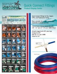
How to use the Quick-Connect fittings on the RO Module<br />
To make a connection, the tube is simply pushed into the fitting.<br />
Place a piece of tape 1 /2" from end of tube to indicate how far the<br />
tube should be inserted. The unique patented Quick-Connect<br />
locking system holds the tube firmly in place without deforming it or<br />
restricting flow.<br />
Cut the tube square. It is essential that the outside diameter be free of score marks<br />
and that burrs and sharp edges be removed before inserting into fitting.<br />
Fitting grips before it seals. Ensure tube is pushed into the tube stop.<br />
Push the tube into the fitting, to the tube stop. The collet (gripper) has stainless<br />
steel teeth which hold the tube firmly in position while the O-ring provides a permanent<br />
leak proof seal.<br />
Pull on the tube to check that it is secure. It is a good practice to test the system<br />
prior to leaving site and /or before use.<br />
To disconnect, ensure the system is depressurized before removing the tube. Push<br />
in collet squarely against face of fitting. With the collet held in this position, the tube<br />
can be removed. The fitting can then be reused.<br />
4
STEP 2<br />
<strong>Watts</strong> Chrome Top Mount<br />
Faucet Installation<br />
Minimum<br />
Maximum<br />
Mounting Hole Size 1" 1 1 ⁄4"<br />
Torque on Toggle Bolt<br />
5 lb.in. (max)<br />
Gather and identify the faucet pieces.<br />
Step A - Remove faucet base and faucet spout from their respective<br />
plastic bags. From above the sink, feed the faucet tubing<br />
& toggle bolt down through the 1¼" mounting hole in the<br />
sink. Ensure that the soft rubber gasket has the protective<br />
white paper removed from both sides and is uniformly<br />
positioned in between the base of the faucet and the top of<br />
the sink.<br />
Step B - Align the faucet base so that the handle is on the right side<br />
and the base is sitting flush on the sink top. Using a phillips<br />
head screwdriver, turn the screw located down the hole<br />
where the spout will be installed, clockwise until the toggle<br />
bolt secures the faucet base snug onto the sink top.<br />
Step C - Once the faucet base is securely fastened to the sink top,<br />
insert the faucet spout into the faucet base until it is fully<br />
seated. Turn the handle up (away from you) to the “OFF”<br />
position.<br />
Step D - Connect the loose end of the 3 ⁄8" blue plastic tubing from<br />
the faucet to the 3 ⁄8" plastic fitting from the final inline filter.<br />
STEP 3<br />
Adapt-A-Valve Installation<br />
Verify contents prior to installation:<br />
( 1 ) - Plastic Adapt-a-Valve & Black Collet<br />
( 1 ) - Brass Adapter no washer<br />
( 1 ) - Brass Adapter with black washer<br />
( 1 ) - White rubber washer<br />
<strong>Water</strong> supply line to the system must be from the cold water<br />
supply line only. Hot water will severely damage your system.<br />
WARNING: Do not use Teflon tape with the Adapt-A-Valve.<br />
For 3 ⁄8" Configuration<br />
(With Brass Fittings)<br />
* Insert White Washer<br />
For 1 ⁄2" Configuration<br />
Hot<br />
Supply<br />
Cold<br />
Supply<br />
(Without Brass Fittings)<br />
1<br />
⁄2" Configuration<br />
Hot<br />
Supply<br />
Cold<br />
Supply<br />
Step A - Turn off the cold water supply to the faucet by turning the<br />
angle stop valve completely off.<br />
Step B - Open cold water sink faucet to relieve pressure.<br />
Step C - Choosing the configuration that fits your plumbing, attach<br />
the Adapt-A-Valve as illustrated in the four photos<br />
above.<br />
STEP 4<br />
Reverse Osmosis Module Mounting<br />
Step A – Determine best location for the<br />
RO module to be mounted to<br />
allow for future system maintenance.<br />
The parts bag has 2<br />
self-tapping screws. Using an<br />
electric drill with a Phillips bit,<br />
screw them into the cabinet<br />
wall 6" apart and 16" from the<br />
bottom of the cabinet.<br />
Note: Do not cut any RO system tubes at this time<br />
5
STEP 5<br />
Green Tube Connection<br />
Step A – Locate green tube attached to the<br />
RO Module. Insert the open end of<br />
the green 1 ⁄4" tube into the open 1 ⁄4"<br />
quick-connect fitting on the Adapt-<br />
A-Valve making sure the tube is<br />
pushed in all the way to the tube<br />
stop.<br />
Step B – Connect the green tube from the RO<br />
module to the Adapt-A-Valve that<br />
is connected to the cold water angle<br />
stop valve. Leave enough tube so it is not kinked and cut<br />
the tube to the desired length.<br />
STEP 8<br />
Tank Ball Valve Installation<br />
Step A – Teflon ® tape must be applied<br />
in a clockwise direction. Wrap<br />
(4 to 8 turns) around the male<br />
pipe threads (MPT) on the<br />
stainless steel fitting on top of<br />
the tank.<br />
Step B – Thread the Quick-Connect<br />
ball valve (supplied in the<br />
parts bag) onto the stainless<br />
steel connector on the tank.<br />
STEP 6<br />
Black Tube Connection<br />
Step A – Locate black tube attached to the<br />
RO Module. Insert the open end of<br />
the black 1 ⁄4" tube into the open 1 ⁄4"<br />
quick-connect fitting on the Adapt-<br />
A-Valve making sure the tube is<br />
pushed in all the way to the tube<br />
stop.<br />
Step B – Connect the black tube from the RO<br />
module to the Adapt-A-Valve that<br />
is connected to the hot water angle<br />
stop valve. Leave enough tube so it is not kinked and cut<br />
the tube to the desired length.<br />
STEP 7<br />
Check Air Pressure in the Tank<br />
Note: Check air pressure when tank is empty of water!<br />
Check air pressure in the storage tank when you notice a decrease<br />
in available water from the RO system. Air can be added<br />
with a bicycle pump using the schrader valve that is located on<br />
the lower side of the tank behind the blue plastic cap.<br />
Step A – Turn off the incoming water<br />
supply to the RO by turning the<br />
knob on the Adapt-A-Valve<br />
clockwise until it stops. (Follow<br />
the green tube away from the<br />
RO system to find the Adapt-A-<br />
Valve.)<br />
Step B – Open the RO Faucet and allow water to drain from the tank<br />
until it is completely empty.<br />
Tip: When water from the RO faucet slows to a trickle, with the<br />
faucet still in the open position, you may add air to the tank to<br />
purge any left over water. This will ensure that the tank is completely<br />
empty.<br />
Step C – Once all water in the tank is purged, check air pressure using<br />
an air pressure gauge, it should read between 5 - 7psi.<br />
(Digital air pressure gauge is recommended)<br />
Step D – Follow startup procedure on Page 7.<br />
Caution: Do not Teflon ® tape the<br />
plastic elbow threads as this may cause<br />
leaks.<br />
STEP 9<br />
Final Filter Installation<br />
Step A – Locate 3<br />
/8" blue tubing in parts bag. The final polishing filter<br />
is clipped onto the top of the membrane housing. Connect<br />
one open end of 3 /8" blue tubing to the quick-connect fitting<br />
labeled "Faucet" located on the final polishing filter. Make<br />
sure that the tube is pushed in all the way to the tube stop.<br />
Step B – Connect the other end of the 3 /8" blue tubing connected to<br />
the in-line filter to the quick-connect fitting located on the<br />
faucet shank.<br />
Note: A connection to a refrigerator / ice maker may be tee’d<br />
into this blue tube and should be spliced in between the final<br />
filter and the RO faucet.<br />
Teflon ® is a registered trademark of E.I. Dupont de Nemours & Company.<br />
6
Start Up Instructions<br />
Warning: To prevent the possibility of electrical shock, clean up<br />
any water on cabinet floor and dry all water from outside of RO<br />
unit.<br />
Step A– Turn on the incoming cold and hot water at the angle stop<br />
valves by turning the knob on the Adapt-A-Valve counterclockwise.<br />
Check the system for leaks and tighten push<br />
to be further in any fittings as necessary. (Check frequently<br />
over the next 24 hours to ensure no leaks are present).<br />
Note: If you have connected your RO system to a refrigerator /<br />
ice maker, make sure the ice maker is off (do not allow water to<br />
flow to the ice maker) until flushing is complete and the tank has<br />
been allowed to fill completely. Connection from the RO to the<br />
ice maker system should have an in-line valve installed before<br />
the ice maker so it can easily be closed to prevent water flowing<br />
to the ice maker during start up and periodic maintenance. Your<br />
RO tank must be allowed to fill up fully in order for the ice maker<br />
system to work properly.<br />
Step B – Plug the 24 volt transformer power cord connector into the<br />
RO wire harness connector (labeled Transformer).<br />
Step C – Plug the transformer into the electrical outlet under the<br />
sink.<br />
Step D – Open the RO faucet and leave it open until water begins to<br />
trickle out (it will come out slowly).<br />
Step E – After water trickles out of the faucet, close the RO faucet<br />
allowing the storage tank to fill with water. It may take 4 to<br />
6 hours to fill the tank completely depending on the production<br />
capability of the membrane, local water temperature<br />
and water pressure.<br />
Note: Ensure Ball Valve on the RO storage tank is open.<br />
Note: During the fill period, you may hear water trickling due to<br />
the Reverse Osmosis Process.<br />
Step F – After the Tank has filled, open the RO Faucet to flush the<br />
tank completely to remove carbon particles from final filter.<br />
You will know that the tank is empty when the flow rate<br />
from the RO faucet is down to a trickle. Repeat this step<br />
two more times. The fourth tank can be used for drinking.<br />
Note: Flushing of the tank 3 times is only necessary during the<br />
initial startup and after replacing the membrane.<br />
Important: Your reverse osmosis system contains replaceable<br />
treatment components that are critical for effective containment<br />
reduction. Periodic inspection and following proper system<br />
maintenance is critical for continued performance.<br />
7
6-Month System Maintenance<br />
Order filter by calling <strong>Watts</strong> at 1-800-224-1299<br />
Item Needed: EDP# 7100110<br />
<strong>Inc</strong>ludes:<br />
• (1) Sediment Filter • (1) Carbon Block Filter<br />
Step A – Turn off the incoming water supply to the RO by turning the<br />
knob on the Adapt-A-Valve clockwise until it stops.<br />
Step B – Open the RO Faucet and allow water to drain from the tank<br />
until it is completely empty.<br />
Note: <strong>Water</strong> may be saved in a container for drinking or to rinse<br />
system parts.<br />
Step C – Let system sit for 10 to 15<br />
minutes after the tank is empty<br />
to let the system depressurize<br />
before attempting to remove<br />
filter housings.<br />
Step D – For more leverage you may<br />
leave the RO module attached<br />
to wall of cabinet. If you are<br />
unable to access the module<br />
while it is mounted, remove it<br />
prior to changing filters. Starting<br />
with the closest housing<br />
(Stage 1), remove it by turning<br />
it clockwise (left), empty water,<br />
then discard filter. Continue on<br />
to the 2nd housing (Stage 2)<br />
and 3rd housing (Stage 3).<br />
Note: If you own a 4-Stage system, it will not have the third<br />
stage. A 4-Stage system has two vertical housings instead of<br />
three.<br />
Annual Maintenance<br />
Order filter by calling <strong>Watts</strong> at 1-800-224-1299<br />
Item Needed: # 7100115<br />
1/2 cup of hydrogen peroxide or household bleach.<br />
<strong>Inc</strong>ludes:<br />
• (1) Sediment Filter • (1) Membrane<br />
• (1) Carbon Block Filters • (1) Final Inline Filter<br />
Note: Sanitizing of unit is recommended.<br />
Step A – Perform steps A through E in the Six Month System Maintenance.<br />
Note: If not sanitizing the system skip to step H.<br />
Step B – Remove the RO membrane from its housing and rest in a<br />
clean sanitary place. (Refer to “Membrane Replacement”<br />
section on Page 9 for directions on removing the membrane).<br />
Replace cap onto empty membrane housing and<br />
re-connect green tubing.<br />
Step C – Leaving the filters out, replace Stage 1 and 2 empty filter<br />
housings (hand tight) onto unit. Measure & pour either 1 ⁄2<br />
cup of hydrogen peroxide or common household bleach<br />
into the 1st filter housing (Stage 1) and hand tighten onto<br />
unit.<br />
Step D – With the RO faucet in the closed position turn on the<br />
incoming water supply to the system by turning the Adapt-<br />
A-Valve counterclockwise. Wait 1 minute for the unit to<br />
pressurize. Turn on the RO faucet and let the water run for<br />
30 seconds. Turn off the RO faucet and let the unit rest for<br />
2 minutes. Finally, open the RO faucet and let the water run<br />
for 5 more minutes.<br />
8<br />
Step E – Clean the filter housings (bowls)<br />
with a mild soap solution and<br />
rinse with water. Check O-rings<br />
and lubricate with water soluble<br />
lubricant. KY Jelly ® , canola oil<br />
or other water based lubricants<br />
may be used. Petroleum<br />
based lubricants (such as<br />
Vaseline ® ) must not be used.<br />
Caution: Before re-installing the filter bowls back on to the system,<br />
check O-rings to make sure they are still in place.<br />
Step F – Insert a new sediment filter<br />
(cloth like appearance) into<br />
the 1st filter housing which is<br />
the one on the water inlet side<br />
(green tubing from the Adapt-<br />
A-Valve) of the RO system<br />
and re-install housing.<br />
Step G – Insert the new Carbon Block<br />
filter (White end caps & plastic netting) into the second and<br />
third filter bowls and re-install housings.<br />
Do not over-tighten filter housing, overtightening may damage<br />
O-ring(s), cause water leaks, or affect system performance.<br />
Step H – Turn water supply on to the unit by turning the knob on the<br />
Adapt-A-Valve counterclockwise.<br />
Step I – Open the RO faucet and leave it open until water begins to<br />
trickle out (it will come out slowly).<br />
Step J – Close the RO faucet allowing the storage tank to fill with<br />
water. It may take 4 to 6 hours to fill the tank completely<br />
depending on the production capability of the membrane,<br />
local water temperature and water pressure.<br />
Step E – Turn off the incoming water supply to the system by turning<br />
the Adapt-A-Valve clockwise until it stops. Keep the RO<br />
faucet open until the storage tank is completely drained.<br />
Step F – Open the membrane housing and re-install the RO membrane<br />
while making sure not to kink the O-rings. (Refer to<br />
“Membrane Replacement” section on Page 9 for directions<br />
on installing the membrane). Tighten the cap back on the<br />
housing and reconnect green tubing.<br />
Step G – Remove filter housings Stage 1 and 2 and empty of water.<br />
Caution: Before re-installing the filter bowls back on to the<br />
system , check O-rings to make sure they are still in place and<br />
lubricate with water soluble lubricant.<br />
Step H – Insert the new sediment filter (cloth like appearance) into<br />
the 1st filter housing which is the one on the water inlet<br />
side (green tubing from the Adapt-A-Valve) of the RO<br />
system and re-install housing.<br />
Step I – Insert the new Carbon Block filter (White End Caps) into the<br />
2nd housing and re-install housing.<br />
Do not over-tighten filter housing, overtightening may damage<br />
O-ring(s), cause water leaks, or affect system performance.<br />
Step J – The final in-line filter is located on the blue tube between<br />
the storage tank and the RO faucet. Remove it by loosening<br />
the compression fittings on both ends of the filter and<br />
replace with new filter. (Discard used final filter after sanitizing).<br />
Note: The arrow on the final filter must be pointing towards the<br />
RO faucet / away from the RO storage tank.<br />
This is a good time to check the air pressure in your storage<br />
tank. For instructions please see Page 9.<br />
Step K – Follow Steps H through J in the Six Month System Maintenance<br />
(Page 8) for startup directions.
Membrane Replacement<br />
This reverse osmosis system contains a replaceable component (the<br />
RO membrane) which is critical to the efficiency of the system.<br />
Replacement of this reverse osmosis membrane should be with one<br />
of identical specifications as defined by <strong>Watts</strong> to assure the same<br />
efficiency and contaminant reduction performance.<br />
Membranes have a life expectancy between 2 and 5 years, depending<br />
on the incoming water conditions and the amount the<br />
RO system is used. This reverse osmosis membrane is critical for<br />
effective reduction of total dissolved solids (TDS). The product water<br />
should be tested periodically to verify that the system is performing<br />
satisfactorily.<br />
Normally, a membrane would be replaced during a semiannual or<br />
annual filter change. However, if at any time you notice a reduction<br />
in water production or an unpleasant taste in the reverse osmosis<br />
water, it could be time to replace the membrane. <strong>Watts</strong> recommends<br />
replacing the membrane when TDS reduction falls below 75%.<br />
Note: A water sample may be sent to <strong>Watts</strong> for a free diagnosis<br />
of your membrane performance. To send a water sample,<br />
use two (2) clean containers and fill ½ cup of tap water in one<br />
container and ½ cup of reverse osmosis water in 2nd container.<br />
Clearly label each sample. Send the samples to the address<br />
listed on the cover of this manual attention “<strong>Water</strong> Samples”.<br />
<strong>Watts</strong> will test the water and mail or call you with the results.<br />
Step A – Turn off the incoming water<br />
supply to the RO by turning<br />
the knob on the Adapt-A-<br />
Valve clockwise until it<br />
stops.<br />
Step B – Open the RO Faucet and<br />
allow water to drain from<br />
the tank until it is completely<br />
empty.<br />
Removing the Membrane<br />
Step A – Use a 5<br />
⁄8" wrench to remove the Green Tube fitting on the<br />
left side of the horizontal membrane housing (end with one<br />
elbow).<br />
Step B – Remove the cap from the membrane housing by turning it<br />
counterclockwise to loosen.<br />
Note: A double sided wrench may<br />
be purchased from <strong>Watts</strong> to aid with<br />
loosening the cap / filter housings.<br />
Step C – Remove membrane housing<br />
from the holding clips. Using<br />
a pair of pliers, grip the PVC<br />
tube of the RO membrane and<br />
pull firmly on the membrane to<br />
remove from the housing and<br />
discard.<br />
Installing the Membrane<br />
Step A – Lubricate the O-rings on the new membrane with a water<br />
soluble lubricant such as KY Jelly ®. Insert the end with the<br />
two black O-rings first into the<br />
housing.<br />
Step B – Once membrane has been<br />
inserted into the housing you<br />
must take your thumbs and<br />
give a firm push to properly<br />
seat the membrane. Replace<br />
membrane housing cap and<br />
tighten.<br />
Step C – After replacing membrane<br />
housing into clips, attach the<br />
green tube to the elbow on<br />
cap using 5 ⁄8" wrench.<br />
Step D – Follow the Start Up Instructions<br />
on Page 7.<br />
Procedure for Extended Non-Use<br />
(More than 2 months)<br />
Turn off the water supply by turning the knob on the Adapt-A-<br />
Valve clockwise until it stops and open the RO faucet to empty<br />
the storage tank (Save a few ounces of RO water). Once the storage<br />
tank is empty, remove the membrane and place it in a sealed plastic<br />
bag with the RO water saved earlier and store in your refrigerator.<br />
For restart, reinstall membrane (See Page 9 for membrane installation<br />
procedure) and follow startup procedure on Page 7.<br />
9
Troubleshooting<br />
Problem Cause Solution<br />
1. Low/slow production Excessive air pressure in tank Relieve pressure at schrader valve on tank (set to 7psi with<br />
the tank empty)<br />
Pump not operating<br />
Fouled membrane<br />
Plugged pre-filters<br />
Crimped tubing<br />
Angle stop or water line valve not fully opened<br />
Wiring connection broken (plug 110 AC wall, plug back in at<br />
wall and/or reconnect the 24 VAC wire harness connectors)<br />
Replace pump if needed<br />
Replace membrane<br />
Replace filters<br />
Check tubes to make sure they are not kinked<br />
Ensure valves are opened by turning valve handle counterclockwise<br />
until it stops<br />
2. Milky colored water Air in the system Air in the system is a normal occurrence with initial start<br />
up of the RO system. This milky look will disappear during<br />
normal use within 1-2 weeks. If condition reoccurs after filter<br />
changes, drain tank 1 to 2 times.<br />
3. Faucet Dripping Needs adjustment see page 12<br />
4. Pump short cycles Ball valve on tank closed Open the ball valve on the top of the tank<br />
Blue tube blocked between the tank and RO system Faulty<br />
pressure switch<br />
Remove kinked/damaged section and replace if necessary<br />
Call for technical support<br />
5. Bowl leaks at the top after changing the filters Damaged/Dry O-ring Lubricate with water soluble lubricant or replace O-ring as<br />
necessary (Do not use Vaseline® or other petroleum based<br />
lubricants)<br />
6. Pump constantly running Electrical fault Faucet left on Call for technical support. Close faucet and let tank fill for 2<br />
to 3 hours.<br />
Plugged pre-filters<br />
Replace filters<br />
10
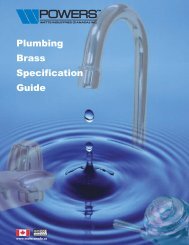
Parts List<br />
9<br />
FAUCET<br />
30<br />
1/4”-3/8” QC<br />
ADAPTER<br />
1/4” BLUE TUBE<br />
15<br />
11<br />
CARBON<br />
POST-FILTER<br />
FLOW<br />
TEE<br />
FITTING<br />
1/4” BLUE TUBE<br />
22<br />
2<br />
2<br />
21<br />
1/4” BLUE TUBE<br />
CHECK<br />
4 VALVE<br />
5<br />
PRESSURE<br />
SWITCH<br />
1/4” BLACK TUBE - BRINE<br />
23<br />
FLOW<br />
RESTRICTOR<br />
18<br />
18<br />
12<br />
26 MEMBRANE HOUSING<br />
PERMEATE<br />
18<br />
7<br />
TRANSFORMER<br />
1/4” GREEN TUBE<br />
28 STORAGE TANK<br />
3 3<br />
17<br />
25<br />
20<br />
25<br />
14<br />
19<br />
27 27<br />
8<br />
SELENOID<br />
19<br />
13 10<br />
TO<br />
KITCHEN<br />
SINK<br />
TO<br />
KITCHEN<br />
SINK<br />
24<br />
24<br />
16<br />
16<br />
1/4” GREEN TUBE<br />
FEED <strong>WATER</strong><br />
1<br />
ADAPT-A-VALVE<br />
1<br />
ADAPT-A-VALVE<br />
6 PUMP<br />
HOT-<strong>WATER</strong><br />
SHUT-OFF VALVE<br />
COLD-<strong>WATER</strong><br />
SHUT-OFF VALVE<br />
SEDIMENT<br />
PRE-FILTER<br />
CARBON<br />
PRE-FILTER<br />
Item EDP Description<br />
1 7300068 ADAPT-A-VALVE<br />
2 7300077<br />
MOUNTING CLIP - DOUBLE - INLINE FILTER TO MEMBRANE<br />
HOUSING<br />
3 7300049 MOUNTING CLIP - MEMBRANE HOUSING<br />
4 7300075 DOUBLE CHECK VALVE<br />
5 7300015 PRESSURE SWITCH<br />
6 7300001 BOOSTER PUMP - 1/4" QC<br />
7 7300000 TRANSFORMER<br />
8 7300076 SELENOID VALVE<br />
9 7100203 TOP MOUNT FAUCET - CHROME<br />
10 7100446 CARBON BLOCK FILTER<br />
11 7100454 GAC POST-FILTER<br />
12 710122 REVERSE OSMOSIS MEMBRANE<br />
13 7100330 SEDIMENT FILTER<br />
14 7300039 CONNECTOR - 1/4" M X 1/4" QC<br />
15 7300029 CONNECTOR - 3/8"C X 1/4" M<br />
11<br />
Item EDP DESCRIPTION<br />
16 7300034 ELBOW - 1/4" QC X 1/4" STEM<br />
17 7300031 ELBOW - 1/4" C X 1/4" M<br />
18 7300032 ELBOW - 1/4" C X 1/8" M<br />
19 7300033 ELBOW - 1/4" QC X 1/8" M<br />
20 7300036 BRASS HEX NIPPLE-BRASS - 1/4"M<br />
21 7300073 TANK SHUT-OFF VALVE<br />
22 7300038 TEE - MALE RUN 1/4" T X 1/4" M<br />
23 7300025 FLOW RESTRICTOR (not shown)<br />
24 7300044 FILTER HOUSING - BOWL - 10" - WHITE<br />
25 7300081 FILTER HOUSING - LID - 1/4" PORTS<br />
26 7300042 MEMBRANE HOUSING<br />
27 7300060 O-RINGS FOR FILTER HOUSING<br />
28 7100174 STORAGE TANK - 3 GAL WHITE<br />
29 7300090 1/4" x 1/4" UNION<br />
30 7300041 1/4" x 3/8" QC ADAPTOR
Arsenic Facts<br />
Arsenic (As) is a naturally occurring contaminant found in many<br />
ground waters. Arsenic in water has no color, taste or odor. It must<br />
be measured by an arsenic test kit or lab test.<br />
Public water utilities must have their water tested for arsenic. You<br />
can obtain the results from your water utility contained with in your<br />
consumer confidence report. If you have your own well, you will need<br />
to have the water evaluated. The local health department or the state<br />
environmental health agency can provide a list of test kits or certified<br />
labs.<br />
There are two forms of arsenic: pentavalent arsenic (also called As<br />
(V), As (+5)) and trivalent arsenic (also called As (III), As (+3)). In well<br />
water, arsenic may be pentavalent, trivalent, or a combination of<br />
both. Although both forms of arsenic are potentially hazardous to<br />
your health, trivalent arsenic is considered more harmful than pentavalent<br />
arsenic.<br />
RO systems are very effective at removing pentavalent arsenic. A free<br />
chlorine residual will rapidly convert trivalent arsenic to pentavalent<br />
arsenic. Other water treatment chemicals such as ozone and potassium<br />
permanganate will also change trivalent arsenic to pentavalent<br />
arsenic. A combined chlorine residual (also called chloramine) where<br />
it does convert trivalent arsenic to pentavalent arsenic, may not convert<br />
all the trivalent arsenic in to pentavalent arsenic. If you get your<br />
water from a public water utility, contact the utility to find out if free<br />
chlorine or combined chlorine is used in the water system.<br />
This <strong>Watts</strong> reverse osmosis system is designed to remove up to 98%<br />
of pentavalent arsenic. It will not convert trivalent arsenic to pentavalent<br />
arsenic. Under laboratory standard testing conditions, this<br />
system reduced 0.30 mg/L (ppm) pentavalent arsenic to under 0.010<br />
mg/L (ppm) (the USEPA standard for drinking water). Actual performance<br />
of the system may vary depending on specific water quality<br />
conditions at the consumer’s installation. In addition to the independent<br />
laboratory standard testing conditions <strong>Watts</strong> has conducted<br />
additional field testing on our reverse osmosis units to determine<br />
trivalent arsenic reduction capabilities. Based upon <strong>Watts</strong> field testing,<br />
it has been determined that the RO units are capable of reducing<br />
up to 67% of trivalent arsenic from the drinking water.<br />
The RO membrane component of this <strong>Watts</strong> reverse osmosis system<br />
must be maintained according to its recommended maintenance<br />
cycle. Specific component identification and ordering information can<br />
be found in the installation/operation manual maintenance section,<br />
by phone at 1-800-224-1299 or online www.watts.com<br />
12
Service Record<br />
Date of Purchase Date of Install Installed by<br />
Date<br />
1st stage Sediment<br />
(6 months)<br />
2nd stage Carbon<br />
(6 months)<br />
3rd stage Carbon<br />
(6 months)<br />
Final Filter Carbon<br />
(1 year)<br />
TFM Membrane<br />
(2 – 5 years)<br />
Notes:<br />
13
LIMITED WARRANTY: Certain <strong>Watts</strong> Pure <strong>Water</strong> products come with a limited warranty from <strong>Watts</strong> Regulator Co. Other products may have no warranty or are covered by the original manufacturer’s<br />
warranty only. For specific product warranty information, please visit www.watts.com or the published literature that comes with your product. Any remedies stated in such warranties are exclusive and<br />
are the only remedies for breach of warranty. EXCEPT FOR THE APPLICABLE PRODUCT WARRANTY, IF ANY, WATTS MAKES NO OTHER WARRANTIES, EXPRESS OR IMPLIED. TO THE FULLEST EXTENT<br />
PERMITTED BY APPLICABLE LAW, WATTS HEREBY SPECIFICALLY DISCLAIMS ALL OTHER WARRANTIES, EXPRESS OR IMPLIED, INCLUDING BUT NOT LIMITED TO THE IMPLIED WARRANTIES OF<br />
MERCHANTABILITY AND FITNESS FOR A PARTICULAR PURPOSE, AND IN NO EVENT SHALL WATTS BE LIABLE, IN CONTRACT, TORT, STRICT LIABILITY OR UNDER ANY OTHER LEGAL THEORY, FOR<br />
INCIDENTAL, INDIRECT, SPECIAL OR CONSEQUENTIAL DAMAGES, INCLUDING, WITHOUT LIMITATION, LOST PROFITS OR PROPERTY DAMAGE, REGARDLESS OF WHETHER IT WAS INFORMED ABOUT<br />
THE POSSIBILITY OF SUCH DAMAGES.<br />
A <strong>Watts</strong> <strong>Water</strong> <strong>Technologies</strong> Company<br />
USA: Tel. (800) 224-1299 • www.watts.com<br />
Canada: Tel. (888) 208-8927 • www.watts.ca<br />
IOM-WQ-PWRO4ZRO 1225 EDP# 2915899 © 2012 <strong>Watts</strong>