DE2 Development and Education Board User Manual
DE2 Development and Education Board User Manual
DE2 Development and Education Board User Manual

Create successful ePaper yourself
Turn your PDF publications into a flip-book with our unique Google optimized e-Paper software.
CONTENTS<br />
CHAPTER 1 OVERVIEW .......................................................................................................................................... 4<br />
1.1 GENERAL DESCRIPTION ............................................................................................................................................ 4<br />
1.2 KEY FEATURES.......................................................................................................................................................... 5<br />
1.3 BOARD OVERVIEW.................................................................................................................................................... 6<br />
1.4 BLOCK DIAGRAM...................................................................................................................................................... 7<br />
CHAPTER 2 USING THE DE4 BOARD................................................................................................................ 13<br />
2.1 CONFIGURATION OPTIONS ...................................................................................................................................... 13<br />
2.2 SETUP ELEMENTS.................................................................................................................................................... 19<br />
2.3 STATUS ELEMENTS.................................................................................................................................................. 20<br />
2.4 GENERAL USER INPUT/OUTPUT .............................................................................................................................. 21<br />
2.5 HIGH-SPEED MEZZANINE CARDS............................................................................................................................ 25<br />
2.6 GPIO EXPANSION HEADERS ................................................................................................................................... 36<br />
2.7 DDR2 SO-DIMM................................................................................................................................................... 40<br />
2.8 USB OTG............................................................................................................................................................... 48<br />
2.9 SD CARD ................................................................................................................................................................ 51<br />
2.10 CLOCK CIRCUITRY................................................................................................................................................ 52<br />
2.11 PCI EXPRESS......................................................................................................................................................... 56<br />
2.12 GIGABIT ETHERNET (GIGE) .................................................................................................................................. 59<br />
2.13 SERIAL ATA (SATA) ............................................................................................................................................. 62<br />
2.14 RS-232 SERIAL PORT ............................................................................................................................................ 64<br />
2.15 FLASH MEMORY ................................................................................................................................................. 65<br />
2.16 SSRAM MEMORY ................................................................................................................................................ 66<br />
2.17 I2C SERIAL EEPROM .......................................................................................................................................... 68<br />
2.18 TEMPERATURE SENSOR......................................................................................................................................... 68<br />
2.19 POWER.................................................................................................................................................................. 69<br />
CHAPTER 3 CONTROL PANEL............................................................................................................................ 71<br />
3.1 CONTROL PANEL SETUP .......................................................................................................................................... 71<br />
3.2 CONTROLLING THE LEDS AND 7-SEGMENT DISPLAYS ............................................................................................ 75<br />
3.3 SWITCH/BUTTON ............................................................................................................................................... 77<br />
3.4 MEMORY CONTROLLER .......................................................................................................................................... 78<br />
3.5 USB2.0 OTG.......................................................................................................................................................... 81<br />
2
3.6 SD CARD............................................................................................................................................................... 82<br />
3.7 TEMPERATURE MONITOR ........................................................................................................................................ 83<br />
3.8 POWER.................................................................................................................................................................... 84<br />
3.9 PLL ........................................................................................................................................................................ 85<br />
3.10 SATA.................................................................................................................................................................... 86<br />
3.11 HSMC .................................................................................................................................................................. 87<br />
3.12 FAN ....................................................................................................................................................................... 88<br />
CHAPTER 4 DE4 SYSTEM BUILDER.................................................................................................................. 90<br />
4.1 INTRODUCTION ....................................................................................................................................................... 90<br />
4.2 GENERAL DESIGN FLOW......................................................................................................................................... 91<br />
4.3 USING DE4 SYSTEM BUILDER ................................................................................................................................ 92<br />
CHAPTER 5 EXAMPLES OF ADVANCED DEMONSTRATION .................................................................... 103<br />
5.1 USB HOST ............................................................................................................................................................ 103<br />
5.2 USB DEVICE......................................................................................................................................................... 111<br />
5.3 ETHERNET – SIMPLE SOCKET SERVER................................................................................................................... 116<br />
5.4 SD CARD READER ................................................................................................................................................ 124<br />
5.5 DDR2 SDRAM .................................................................................................................................................... 128<br />
5.6 EXTERNAL CLOCK GENERATOR ............................................................................................................................ 132<br />
5.7 POWER MEASUREMENT ........................................................................................................................................ 137<br />
5.8 WEB SERVER......................................................................................................................................................... 141<br />
5.9 SERIAL ATA (SATA) ............................................................................................................................................. 150<br />
5.10 HIGH-SPEED MEZZANINE CARD (HSMC)........................................................................................................... 151<br />
CHAPTER 6 PCI EXPRESS REFERENCE DESIGN ....................................................................................... 154<br />
6.1 PCI EXPRESS SYSTEM INFRASTRUCTURE.............................................................................................................. 154<br />
6.2 FPGA PCI EXPRESS SYSTEM DESIGN................................................................................................................... 155<br />
6.3 PC PCI EXPRESS SYSTEM DESIGN ........................................................................................................................ 159<br />
6.4 FUNDAMENTAL COMMUNICATION......................................................................................................................... 168<br />
6.5 EXAMPLE 2: IMAGE PROCESS APPLICATION .......................................................................................................... 172<br />
ADDITIONAL INFORMATION ................................................................................................................................... 177<br />
3
Chapter 1<br />
Overview<br />
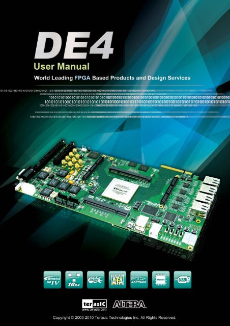
This chapter provides an overview of the DE4 <strong>Development</strong> <strong>Board</strong> <strong>and</strong> details the components <strong>and</strong><br />
features of the board.<br />
1.1 General Description<br />
The DE4 <strong>Development</strong> <strong>Board</strong> provides the ideal hardware platform for system designs that dem<strong>and</strong><br />
high-performance, serial connectivity, <strong>and</strong> advanced memory interfacing. Developed specifically to<br />
address the rapidly evolving requirements in many end markets for greater b<strong>and</strong>width, improved<br />
jitter performance, <strong>and</strong> lower power consumption. The DE4 is powered by the Stratix® IV GX<br />
device <strong>and</strong> supported by industry-st<strong>and</strong>ard peripherals, connectors <strong>and</strong> interfaces that offer a rich set<br />
of features that is suitable for a wide range of compute-intensive applications.<br />
The advantages of the Stratix® IV GX FPGA platform with integrated transceivers have allowed<br />
the DE4 to fully compliant with version 2.0 of the PCI Express st<strong>and</strong>ard. This will accelerate<br />
mainstream development of PCI Express-based applications enabling customers to deploy designs<br />
for a broad range of high-speed connectivity applications. The DE4 coupled with serial ATA (SATA)<br />
interfaces, offer a solution for developing storage applications. The DE4 delivers fully tested <strong>and</strong><br />
supported connectivity targeted reference design that integrates built-in blocks for PCI Express,<br />
SATA transceiver verification testing, <strong>and</strong> Gigabit Ethernet protocol.<br />
The DE4 is supported by multiple reference designs <strong>and</strong> two High-Speed Mezzanine Card (HSMC)<br />
connectors that allow scaling <strong>and</strong> customization with mezzanine daughter cards. For large-scale<br />
ASIC prototype development, it can be established by a cable connecting to multiple DE4/FPGA<br />
boards through the HSMC connectors.<br />
It is highly recommended that users read the DE4 Getting Started Guide.pdf before using the DE4<br />
board.<br />
4
1.2 Key Features<br />
The following hardware is implemented on the DE4 board:<br />
• Featured device<br />
o Altera Stratix® IV GX FPGA (EP4SGX230C2/EP4SGX530C2)<br />
• Configuration status <strong>and</strong> set-up elements<br />
o Built-in USB Blaster circuit for programming<br />
o Fast passive parallel (FPP) configuration via MAX II CPLD <strong>and</strong> flash memory<br />
o Three External Programmable PLL timing chip<br />
• Component <strong>and</strong> interfaces<br />
o Four Gigabit Ethernet (GigE) with RJ-45 connector<br />
o Two host <strong>and</strong> two device Serial ATA (SATA II) ports<br />
o Two HSMC connectors<br />
o Two 40-pin expansion headers<br />
o PCI Express 2.0 (x8 lane) connector<br />
• Memory<br />
o DDR2 SO-DIMM socket<br />
o FLASH<br />
o SSRAM<br />
o SD Card socket<br />
o I2C EEPROM<br />
• General user input/output:<br />
o 8 LEDs<br />
o 4 push-buttons <strong>and</strong> 4 slide switches<br />
o 8-position DIP switch<br />
o 2 seven-segment displays<br />
• Clock system<br />
o On-board clock oscillators: 50MHz <strong>and</strong> 100MHz<br />
o SMA connectors for external clock input<br />
o SMA connectors for clock output<br />
5
• Other interfaces<br />
o USB 2.0 high-speed host/device OTG<br />
o Current sensor for FPGA current measurement<br />
o Temperature sensor<br />
1.3 <strong>Board</strong> Overview<br />
Figure 1–1 <strong>and</strong> Figure 1–2 is the top <strong>and</strong> bottom view of the DE4 board. It depicts the layout of the<br />
board <strong>and</strong> indicates the location of the connectors <strong>and</strong> key components. <strong>User</strong>s can refer to this<br />
figure for relative location when the connectors <strong>and</strong> key components are introduced in the following<br />
chapters.<br />
Figure 1–1 The DE4 board (Top view)<br />
6
Figure 1–2 The DE4 board (Bottom view)<br />
1.4 Block Diagram<br />
Figure 1–3 shows the block diagram of the DE4 board. To provide maximum flexibility for the<br />
users, all key components are connected with the Stratix IV GX FPGA device. Thus, users can<br />
configure the FPGA to implement any system design.<br />
7
Figure 1–3 Block diagram of the DE4 board<br />
Below is more detailed information regarding the blocks in Figure 1–3.<br />
8
Stratix IV GX FPGA<br />
• EP4SGX230C2<br />
o 228,000 logic elements (LEs)<br />
o 17,133K total memory Kbits<br />
o 1,288 18x18-bit multipliers blocks<br />
o 2 PCI Express hard IP blocks<br />
o 744 user I/Os<br />
o 8 phase locked loops (PLLs)<br />
• EP4SGX530C2<br />
o 531,200 logic elements (LEs)<br />
o 27,376K total memory Kbits<br />
o 1,024 18x18-bit multipliers blocks<br />
o 4 PCI Express hard IP Blocks<br />
o 744 user I/Os<br />
o 8 phase locked loops (PLLs)<br />
Configuration device <strong>and</strong> USB Blaster circuit<br />
• MAXII CPLD EPM2210 System Controller <strong>and</strong> Fast Passive Parallel (FPP) configuration<br />
• On-board USB Blaster for use with the Quartus II Programmer<br />
• Programmable PLL timing chip configured via MAX II CPLD<br />
• Support JTAG mode<br />
Memory devices<br />
• 64MB Flash (32M x16) with a 16-bit data bus<br />
• 2MB SSRAM (1M x 16)<br />
• 2Kb EEPROM<br />
9
Two DDR2 SO-DIMM sockets<br />
• Up to 8GB capacity in total<br />
• Maximum memory clock rate at 400MHz<br />
• Theortical B<strong>and</strong>width over 102Gbps<br />
SD Card socket<br />
• Provides SPI <strong>and</strong> 4-bit SD mode for SD Card access<br />
General user I/O<br />
• 8 user controllable LEDs<br />
• 2 seven-segment displays<br />
• 8 user DIP switches<br />
Push-buttons<br />
• 4 user-defined inputs<br />
• Normally high; generates one active-low pulse when the switch is pressed<br />
Slide switches<br />
• 4 slide switches for user-defined inputs<br />
• When a switch is set to the DOWN or UP position, it causes logic 0 or 1, respectively.<br />
On-<strong>Board</strong> Clocking Circuitry<br />
• 50MHz/100MHz oscillator<br />
• 2 SMA connector for external transceiver clock input<br />
• 4 SMA connector for LVDS clock input/output<br />
• 2 SMA connectors for clock output<br />
• 1 SMA connector for external clock input<br />
10
Four Serial ATA ports<br />
• SATA 3.0 st<strong>and</strong>ard 6Gbps signaling rate<br />
Four Gigabit Ethernet ports<br />
• Integrated 1.25GHz SERDES<br />
PCI Express x8 edge connector<br />
• Support connection speed of Gen1 at 2.5Gbps/lane to Gen2 at 5.0Gbps/lane<br />
• Connection established with PC motherboard with x8 or x16 PCI Express slot<br />
Two High Speed Mezzanine Card (HSMC)<br />
• 2 female-HSMC connectors<br />
• Total of 12 pairs CDR-based transceivers at data rate up to 8.5Gbps<br />
• Total 38 LVDS transmitter channels at data rate up to 1.6Gbps, <strong>and</strong> 36 LVDS receiver channels<br />
• I/O voltage 2.5V<br />
Two 40-pin expansion headers<br />
• 72 FPGA I/O pins, as well as 4 power <strong>and</strong> ground lines, are brought out to two 40-pin<br />
expansion connectors<br />
• 40-pin header is designed to accept a st<strong>and</strong>ard 40-pin ribbon cable used for IDE hard drives<br />
• Compatible with I/O st<strong>and</strong>ard 3.3V<br />
11
USB Host/Slave controller<br />
• Complies fully with Universal Serial Bus Specification Rev. 2.0<br />
• Support data transfer at high-speed, full-speed, <strong>and</strong> low-speed<br />
• Support both USB host <strong>and</strong> device<br />
• Three USB ports (one type mini-AB for host/device <strong>and</strong> two type A for host)<br />
• Support Nios II with the Terasic driver<br />
Power<br />
• St<strong>and</strong>alone DC inputs 12V <strong>and</strong> 3.3V<br />
• PCI Express edge connector power<br />
• Optional PCI Express external power source<br />
• On-<strong>Board</strong> power measurement circuitry<br />
12
Chapter 2<br />
Using the DE4 <strong>Board</strong><br />
This chapter gives instructions for using the DE4 board <strong>and</strong> its components.<br />
It is strongly recommended that users read the DE4 Getting Started Guide.pdf before using the DE4<br />
board. The document is located in the <strong>User</strong>manual folder on the DE4 System CD. The contents of<br />
the document include the following:<br />
• Introduction to the DE4 development board<br />
• DE4 development kit contents<br />
• Key features<br />
• Before you begin<br />
• Software Installation<br />
• <strong>Development</strong> board setup<br />
• Programming the Stratix IV GX device on the DE4 board<br />
• Programming through the Flash memory device<br />
2.1 Configuration Options<br />
• JTAG FPGA Programming over USB-Blaster<br />
The USB-blaster is implemented on the DE4 board to provide JTAG configuration through onboard<br />
USB-to-JTAG configuration logic using a type-B USB connector, a FTDI USB 2.0 Controller, <strong>and</strong><br />
an Altera MAX II CPLD. Current configuration will be lost when the power is turned off. Figure<br />
2–1 illustrates the JTAG configuration scheme for the DE4.<br />
13
To download a configuration bit stream into the Stratix IV GX FPGA, perform the following steps:<br />
• Make sure that power is provided to the DE4 board<br />
• Connect the USB cable supplied directly to the USB Blaster port of the DE4 board<br />
• The FPGA can now be programmed in the Quartus II Programmer by selecting a configuration<br />
bit stream file with the .sof filename extension.<br />
Please refer to DE4 Getting Started Guide.pdf for more detailed procedure of FPGA programming.<br />
Figure 2–1 JTAG configuration scheme<br />
• Flash Programming<br />
The DE4 development board contains a common flash interface (CFI) flash memory to meet the<br />
dem<strong>and</strong>s for a larger FPGA configuration storage. The parallel flash loader (PFL) feature in MAX<br />
II devices provides an efficient method to program CFI flash memory devices through the JTAG<br />
interface <strong>and</strong> the logic to control configuration from the flash memory device to the Stratix IV GX<br />
FPGA. Figure 2–2 depicts the connection setup between the CFI flash memory, Max II CPLD, <strong>and</strong><br />
Stratix IV GX.<br />
14
Please refer to the DE4 Getting Started Guide.pdf for the basic programming instruction on parallel<br />
flash loader on the CFI flash memory.<br />
Figure 2–2 Flash programming scheme<br />
• Programming Flash Memory using batch file<br />
The DE4 provides a program_flash batch file (\demonstrations\de4_\de4_board_<br />
update_portal\demo_batch\Program_flash) to limit the steps that are taken when users program the<br />
flash memory on the DE4.<br />
Software Requirements:<br />
• Quartus II 9.1 SP2 or later<br />
• Nios II IDE tools 9.1 SP2 or later<br />
Program_flash folder contents:<br />
• Program_flash.bat<br />
• Program_flash.pl<br />
• Program_flash.sh<br />
• de4_board_update_portal.sof<br />
Before you use the program_flash.bat batch file to program the flash memory, make sure the DE4 is<br />
turned on <strong>and</strong> USB cable is connected to the USB blaster port (J5). In addition, place the .sof<br />
<strong>and</strong> .elf file (optional) you wish to program/convert in the Program_flash directory.<br />
15
Programming Flash Memory with .sof using Program_flash.bat<br />
1. Launch the program_flash.bat batch file from the directory (\demonstrations\de4_\de4_board_update_portal\demo_batch\Program_flash) of the DE4 system CD-ROM.<br />
2. The flash program tool shows the menu options.<br />
Figure 2–3 Flash program tools<br />
3. Select option 2.<br />
Figure 2–4 Option 2<br />
16
4. Enter the .sof file name to be programmed onto the flash memory.<br />
Figure 2–5 Enter .sof name to be program<br />
5. The following lines will appear during flash programming: ‘Extracting Option bits SREC’,<br />
‘Extracting FPGA Image SREC’, <strong>and</strong> ‘Deleting intermediate files’. If these lines don’t appear<br />
on the windows comm<strong>and</strong>, programming on the flash memory is not successfully setup. Please<br />
make sure Quartus II 9.1 SP2 <strong>and</strong> Nios II 9.1 IDE SP2 or later is used.<br />
Figure 2–6 Loading .sof file to be program<br />
17
6. Erasing flash.<br />
Figure 2–7 Erasing flash<br />
7. Programming flash.<br />
Figure 2–8 Programming flash<br />
18
8. Programming complete.<br />
Figure 2–9 Programming flash complete<br />
2.2 Setup Elements<br />
• JTAG Control DIP Switch<br />
The JTAG control DIP switch is provided to either remove or include devices in the active JTAG<br />
chain. The JTAG signals (TDI <strong>and</strong> TDO) found on the HSMC connectors <strong>and</strong> PCIe interface can be<br />
enabled using a 3-position DIP switch. In the “OFF” position, the TDI <strong>and</strong> TDO signals are looped,<br />
similarly in the “ON” position, the JTAG signals are bypassed. Table 2–1 lists the position of the<br />
DIP switch <strong>and</strong> their associated interface.<br />
Table 2–1<br />
SW8 JTAG Control DIP Switch<br />
<strong>Board</strong> Reference Signal Name Description Default<br />
SW8.1<br />
SW8.2<br />
SW8.3<br />
JTAG_HSMA_EN<br />
JTAG_HSMB_EN<br />
JTAG_PCIE_EN<br />
On : Bypass HSMA<br />
Off: HSMA In-chain<br />
On: Bypass HSMB<br />
Off: HSMB In-chain<br />
On: Bypass PCI Express<br />
Off : PCI Express In-Chain<br />
On<br />
On<br />
On<br />
19
• PCI Express Control DIP switch<br />
The PCI Express Control DIP switch is provided to enable or disable different configurations of the<br />
PCIe Connector. Table 2–2 lists the switch controls <strong>and</strong> description.<br />
Table 2–2<br />
SW9 PCIe Control DIP Switch<br />
<strong>Board</strong> Reference Signal Name Description Default<br />
SW9.1<br />
SW9.2<br />
SW9.3<br />
PCIE_PRSNT2n_x1<br />
PCIE_PRSNT2n_x4<br />
PCIE_PRSNT2n_x8<br />
On : Enable x1 presence detect<br />
Off: Disable x1 presence detect<br />
On : Enable x4 presence detect<br />
Off: Disable x4 presence detect<br />
On : Enable x8 presence detect<br />
Off: Disable x8 presence detect<br />
Off<br />
Off<br />
On<br />
2.3 Status Elements<br />
The DE4 development board includes status LEDs. Please refer to Table 2–3 for the status of the<br />
LED indicator.<br />
Table 2–3 LED Indicators<br />
<strong>Board</strong> Reference LED Name Description<br />
D9 12-V Power Illuminates when 12-V power is active.<br />
D10 3.3-V Power Illuminates when 3.3-V power is active.<br />
D20<br />
CONF DONE<br />
Illuminates when the FPGA is successfully configured. Driven<br />
by the MAX II CPLD EPM2210 System Controller.<br />
D18<br />
Loading<br />
Illuminates when the MAX II CPLD EPM2210 System Controller<br />
is actively configuring the FPGA. Driven by the MAX II CPLD<br />
EPM2210 System Controller with the Embedded Blaster CPLD.<br />
D19<br />
Error<br />
Illuminates when the MAX II CPLD EPM2210 System Controller<br />
fails to configure the FPGA. Driven by the MAX II CPLD<br />
EPM2210 System Controller.<br />
D12<br />
USB<br />
Blaster Circuit<br />
Illuminates when USB blaster circuit transmits or receives data.<br />
20
D17<br />
D16<br />
RXD1<br />
TXD1<br />
D15<br />
D14<br />
D13<br />
HSMC<br />
Port B Present<br />
HSMC<br />
Port A Present<br />
UART_RXD/GPIO<br />
Expansion 0 IO[7]<br />
UART_TXD/GPIO<br />
Expansion 1 IO[9]<br />
Illuminates when the HSMC port B has a board or cable<br />
plugged-in such that pin 160 becomes grounded. Driven by the<br />
add-in card<br />
Illuminates when the HSMC port A has a board or cable<br />
plugged-in such that pin 160 becomes grounded. Driven by the<br />
add-in card<br />
Illuminates when RS232 receives data or GPIO Expansion 0<br />
IO[7] is transmits or receives.<br />
Illuminates when RS232 transmit data or GPIO Expansion 1<br />
IO[9] is transmits or receives.<br />
USB<br />
Illuminates when USB Jack-Mini-USB port has a device.<br />
Jack-Mini-USB-AB<br />
Port<br />
USB_TYPE_A port<br />
(Top USB)<br />
USB_TYPE_A port<br />
(Bottom USB)<br />
Illuminates when the USB_TYPE_A port has a device.<br />
Illuminates when the USB_TYPE_A port has a device.<br />
2.4 General <strong>User</strong> Input/Output<br />
• Push-buttons<br />
The DE4 board includes six push-buttons that allow you to interact with the Stratix IV GX device.<br />
Each push-button provides a high logic level or a low logic level when it is not pressed or pressed,<br />
respectively. Table 2–4 lists the board references, signal names <strong>and</strong> their corresponding Stratix IV<br />
GX device pin numbers.<br />
<strong>Board</strong><br />
Reference<br />
PB1<br />
PB2<br />
PB3<br />
PB4<br />
Table 2–4 Push-button Pin Assignments, Schematic Signal Names, <strong>and</strong> Functions<br />
Schematic<br />
Signal Name<br />
BUTTON0<br />
BUTTON1<br />
BUTTON2<br />
BUTTON3<br />
Description<br />
High Logic Level when button not<br />
pressed<br />
High Logic Level when button not<br />
pressed<br />
High Logic Level when button not<br />
pressed<br />
High Logic Level when button not<br />
pressed<br />
21<br />
I/O<br />
St<strong>and</strong>ard<br />
3.0-V<br />
3.0-V<br />
3.0-V<br />
3.0-V<br />
Stratix IV GX<br />
Pin Number<br />
PIN_AH5<br />
PIN_AG5<br />
PIN_AG7<br />
PIN_AH8<br />
PB5 CPU_RESET_n FPGA reset 2.5-V PIN_V34<br />
PB6<br />
RE_CONFIGn<br />
Max II EPM2210 System<br />
re-configuration<br />
- -
A CPU reset push-button (CPU_RESET_n) is an input to the Stratix IV GX device. It is intended to<br />
be the master reset signal for FPGA designs loaded into the Stratix IV GX device. The<br />
RE_CONFIGn push-button is used to force a reboot on the MAX II EPM2210 CPLD device.<br />
• Slide Switches <strong>and</strong> DIP Switch<br />
There are also four slide switches <strong>and</strong> one 8-position DIP switch on the DE4 board to provide<br />
additional FPGA input control. Each switch is connected directly to a pin of the Stratix IV GX<br />
FPGA. When a slide switch is in the DOWN position or the UPPER position, it provides a low<br />
logic level or a high logic level to the FPGA, respectively. For 8-position DIP switch, when a switch<br />
is in the DOWN position or the UPPER position, it provides a high logic level or a low logic level<br />
to the FPGA. Table 2–5 <strong>and</strong> Table 2–6 lists the signal names <strong>and</strong> their corresponding Stratix IV GX<br />
device pin numbers for slide switches <strong>and</strong> DIP switch respectively.<br />
Table 2–5<br />
Slide Switches Pin Assignments, Schematic Signal Names, <strong>and</strong> Functions<br />
<strong>Board</strong><br />
Reference<br />
Schematic<br />
Signal Name<br />
Description<br />
I/O<br />
St<strong>and</strong>ard<br />
Stratix IV GX<br />
Pin Number<br />
SW0 SLIDE_SW0 High logic level when SW in the UPPER 2.5-V PIN_J7<br />
SW1 SLIDE_SW1 position<br />
2.5-V PIN_K7<br />
SW2 SLIDE_SW2 3.0-V PIN_AK6<br />
SW3 SLIDE_SW3<br />
2.5-V PIN_L7<br />
Table 2–6 DIP Switch Pin Assignments, Schematic Signal Names, <strong>and</strong> Functions<br />
<strong>Board</strong> Schematic<br />
I/O Stratix IV GX<br />
Description<br />
Reference Signal Name<br />
St<strong>and</strong>ard Pin Number<br />
SW6 SW0 <strong>User</strong>-Defined DIP switch connected to 3.0-V PIN_AB13<br />
SW6 SW1 FPGA device. When the switch is in the 3.0-V PIN_AB12<br />
SW6 SW2 ON position, a logic 0 is selected. 3.0-V PIN_AB11<br />
SW6 SW3 Similarly when the switch is in the OFF 3.0-V PIN_AB10<br />
SW6 SW4<br />
position, a logic 1 is selected.<br />
3.0-V PIN_AB9<br />
SW6 SW5 3.0-V PIN_AC8<br />
SW6 SW6 3.0-V PIN_AH6<br />
SW6 SW7<br />
3.0-V PIN_AG6<br />
22
• LEDs<br />
The DE4 board consists of 8 user-controllable LEDs to allow status <strong>and</strong> debugging signals to be<br />
driven to the LEDs from the designs loaded into the Stratix IV GX device. Each LED is driven<br />
directly by the Stratix IV GX FPGA. The LED is turned on or off when the associated pins are<br />
driven to a low or high logic level, respectively. A list of the pin names on the FPGA that are<br />
connected to the LEDs is given in Table 2–7.<br />
Table 2–7 <strong>User</strong> LEDs Pin Assignments, Schematic Signal Names, <strong>and</strong> Functions<br />
Schematic<br />
<strong>Board</strong><br />
I/O Stratix IV GX<br />
Signal Description<br />
Reference<br />
St<strong>and</strong>ard Pin Number<br />
Name<br />
D1 LED0 <strong>User</strong>-Defined LEDs.<br />
2.5-V PIN_V28<br />
D2 LED1 Driving a logic 0 on the I/O port turns the LED 2.5-V PIN_W28<br />
D3 LED2 ON. Driving a logic 1 on the I/O port turns the 2.5-V PIN_R29<br />
D4 LED3 LED OFF.<br />
2.5-V PIN_P29<br />
D5 LED4 2.5-V PIN_N29<br />
D6 LED5 2.5-V PIN_M29<br />
D7 LED6 2.5-V PIN_M30<br />
D8<br />
LED7<br />
2.5-V PIN_N30<br />
• 7-Segment Displays<br />
The DE4 board has two 7-segment displays. As indicated in the schematic in Figure 2–10, the<br />
seven segments are connected to pins of the Stratix IV GX FPGA. Applying a low or high logic<br />
level to a segment to light it up or turns it off.<br />
Each segment in a display is identified by an index listed from 0 to 6 with the positions given in<br />
Figure 2–11. In addition, the decimal point is identified as DP. Table 2–8 shows the mapping of the<br />
FPGA pin assignments to the 7-segment displays.<br />
23
Figure 2–10 Connection between 7-segment displays <strong>and</strong> Stratix IV GX FPGA<br />
Figure 2–11 Position <strong>and</strong> index of each segment in a 7-segment display<br />
Table 2–8 7-Segment Display Pin Assignments, Schematic Signal Names, <strong>and</strong> Functions<br />
Schematic<br />
<strong>Board</strong><br />
I/O Stratix IV GX<br />
Signal Description<br />
Reference<br />
St<strong>and</strong>ard Pin Number<br />
Name<br />
HEX1 SEG1_D0 <strong>User</strong>-Defined 7-Segment Display. Driving a logic 0 on 2.5-V PIN_E31<br />
HEX1 SEG1_D1 the I/O port turns the 7-segment signal ON. Driving a 2.5-V PIN_F31<br />
HEX1 SEG1_D2 logic 1 on the I/O port turns the 7-segment signal 2.5-V PIN_G31<br />
HEX1 SEG1_D3 OFF.<br />
2.5-V PIN_C34<br />
HEX1 SEG1_D4 2.5-V PIN_C33<br />
HEX1 SEG1_D5 2.5-V PIN_D33<br />
HEX1 SEG1_D6 2.5-V PIN_D34<br />
HEX1 SEG1_DP<br />
2.5-V PIN_AL35<br />
24
HEX0 SEG0_D0 2.5-V PIN_L34<br />
HEX0 SEG0_D1 2.5-V PIN_M34<br />
HEX0 SEG0_D2 2.5-V PIN_M33<br />
HEX0 SEG0_D3 2.5-V PIN_H31<br />
HEX0 SEG0_D4 2.5-V PIN_J33<br />
HEX0 SEG0_D5 2.5-V PIN_L35<br />
HEX0 SEG0_D6 2.5-V PIN_K32<br />
HEX0 SEG0_DP 2.5-V PIN_AL34<br />
2.5 High-Speed Mezzanine Cards<br />
The DE4 development board contains two HSMC interfaces called port A <strong>and</strong> port B. The HSMC<br />
interface provides a mechanism to extend the peripheral-set of an FPGA host board by means of<br />
add-on cards, which can address today’s high speed signaling requirement as well as low-speed<br />
device interface support. The HSMC interfaces support JTAG, clock outputs <strong>and</strong> inputs, high-speed<br />
serial I/O (transceivers), <strong>and</strong> single-ended or differential signaling.<br />
Both the HSMC interfaces connected to the Stratix IV GX device are female HSMC connectors<br />
with each connector having a total of 172pins, including 121 signal pins (120 signal pins +1 PSNTn<br />
pin), 39 power pins, <strong>and</strong> 12 ground pins. The HSMC connector is based on the Samtec 0.5 mm<br />
pitch, surface-mount QSH family of high-speed, board-to-board connectors. The Stratix IV GX<br />
device provides +12 V DC <strong>and</strong> +3.3 V DC power to the mezzanine card through the HSMC<br />
connector. Table 2–9 indicates the maximum power consumption for both HSMC ports A <strong>and</strong> B.<br />
Table 2–9<br />
Power Supply of the HSMC<br />
Supplied Voltage<br />
Max. Current Limit<br />
12V<br />
3A<br />
3.3V 3A<br />
There are three banks in this connector as Figure 2–12 shows the bank arrangement of signals with<br />
respect to the Samtec connector. Table 2–10 <strong>and</strong> Table 2–11 show the mapping of the FPGA pin<br />
assignments to the HSMC connectors.<br />
25
Figure 2–12 HSMC signal <strong>and</strong> bank diagram<br />
• I/O Distribution<br />
The two HSMC interfaces combine have a total of 12 pairs CDR-based transceivers operating up to<br />
8.5Gbps, 38 pairs LVDS transmitter channels at data rates up to 1.6Gbps, <strong>and</strong> 36 pairs LVDS<br />
receiver channels. Independently, Port A of the HSMC connector consists of 4 pairs CDR-based<br />
transceivers, 19 pairs LVDS transmitter channels, <strong>and</strong> 18 pairs LVDS receiver channels. While port<br />
B of the HSMC connector consists of 8 pairs CDR-based transceivers, 19 pairs LVDS transmitter<br />
channels, <strong>and</strong> 18 pairs LVDS receiver channels. Additionally, both ports A <strong>and</strong> B of the HSMC<br />
interfaces have 5 clock inputs <strong>and</strong> 4 clock outputs (2 differential clock inputs <strong>and</strong> outputs).<br />
• I/O St<strong>and</strong>ards<br />
The HSMC interface has programmable bi-directional I/O pins that can be used as 2.5-V. These pins<br />
can also be used as differential I/O st<strong>and</strong>ard including LVDS.<br />
• Using THCB-HMF2 adapter card<br />
The purpose of the HSMC Height Extension Male to Female card (THCB-HMF2) included in the<br />
DE4 kit package is to increase the height of the HSMC connector to avoid any obstruction that<br />
26
might take place as a HSMC daughter card is connected. The THCB-HMF2 adapter card can be<br />
connected to either ports, A or B of the HSMC connector shown in Figure 2–13.<br />
Figure 2–13 Connection setup between THCB-HMF2 adapter card <strong>and</strong> HSMC<br />
• JTAG Chain on HSMC<br />
The JTAG chain on the HSMC can be activated through the 3-position DIP switch (SW8). If there is<br />
no connection established on the HSMC connectors, the 3-position DIP switch (SW8) are to set<br />
‘On’, where the JTAG signals on the HSMC connectors are bypassed illustrated in Figure 2–14.<br />
27
Figure 2–14 JTAG chain for a st<strong>and</strong>alone DE4 board<br />
If the HSMC-based daughter card connected to the HSMC connector uses the JTAG interface, the<br />
3-position DIP switch (SW8) is set to ‘Off’ to which HSMC port is used. In this case, from Figure<br />
2–15 HSMC port A is used where position 1 of the SW8 is set to ‘Off’. Similarly, if the JTAG<br />
interface isn’t used on the HSMC-based daughter card, position 1 of SW8 is set to ‘On’ bypassing<br />
the JTAG signals as shown in Figure 2–16.<br />
Figure 2–15 JTAG chain for a daughter card (uses JTAG) connected to HSMC port A of the DE4<br />
28
Figure 2–16 JTAG chain for a daughter card (JTAG not used) connected to HSMC port A of the DE4<br />
• Multi-FPGA high capacity platform through HSMC<br />
The DE4 offers a choice of two Stratix IV GX devices, EP4SGX230 <strong>and</strong> EPSGX530 which offer<br />
logic elements (LEs) up to 228,000 <strong>and</strong> 531,200, respectively to provide the flexibility for users to<br />
select a suitable device in terms of design capacity. In situations where users’ design exceeds the<br />
capacity of the FPGA, the HSMC interface can be used to connect to other FPGA system boards<br />
creating a multi-FPGA scalable system. Figure 2–17 illustrates a connection setup between two<br />
DE4 boards by connecting through port B <strong>and</strong> Port A of the HSMC connectors using a Samtec<br />
high-speed cable. Notice the JTAG switch (SW8) configuration setup where position 2 is set to<br />
‘Off’ for port B connected on the DE4 <strong>and</strong> position 1 is set to ‘Off’ for port A connected on the DE4,<br />
allowing JTAG chain to be detected for both DE4 boards.<br />
29
Figure 2–17 JTAG chain setup between two DE4 boards using HSMC interface<br />
Table 2–10 HSMC Port B Pin Assignments, Schematic Signal Names, <strong>and</strong> Functions<br />
HSMC Pin # Schematic Signal Name Description I/O St<strong>and</strong>ard<br />
Stratix IV GX<br />
Pin Number<br />
1 HSMB_GXB_TX_p7 Transceiver TX bit 7 1.4-V PCML PIN_B4<br />
2 HSMB_GXB_RX_p7 Transceiver RX bit 7 1.4-V PCML PIN_C2<br />
3 HSMB_GXB_TX_n7 Transceiver TX bit 7n 1.4-V PCML PIN_B3<br />
4 HSMB_GXB_RX_n7 Transceiver RX bit 7n 1.4-V PCML PIN_C1<br />
5 HSMB_GXB_TX_p6 Transceiver TX bit 6 1.4-V PCML PIN_D4<br />
6 HSMB_GXB_RX_p6 Transceiver RX bit 6 1.4-V PCML PIN_E2<br />
7 HSMB_GXB_TX_n6 Transceiver TX bit 6n 1.4-V PCML PIN_D3<br />
8 HSMB_GXB_RX_n6 Transceiver RX bit 6n 1.4-V PCML PIN_E1<br />
9 HSMB_GXB_TX_p5 Transceiver TX bit 5 1.4-V PCML PIN_K4<br />
10 HSMB_GXB_RX_p5 Transceiver RX bit 5 1.4-V PCML PIN_L2<br />
11 HSMB_GXB_TX_n5 Transceiver RX bit 5n 1.4-V PCML PIN_K3<br />
12 HSMB_GXB_RX_n5 Transceiver RX bit 5n 1.4-V PCML PIN_L1<br />
13 HSMB_GXB_TX_p4 Transceiver TX bit 4 1.4-V PCML PIN_M4<br />
14 HSMB_GXB_RX_p4 Transceiver RX bit 4 1.4-V PCML PIN_N2<br />
15 HSMB_GXB_TX_n4 Transceiver TX bit 4n 1.4-V PCML PIN_M3<br />
16 HSMB_GXB_RX_n4 Transceiver RX bit 4n 1.4-V PCML PIN_N1<br />
17 HSMB_GXB_TX_p3 Transceiver TX bit 3 1.4-V PCML PIN_P4<br />
18 HSMB_GXB_RX_p3 Transceiver RX bit 3 1.4-V PCML PIN_R2<br />
19 HSMB_GXB_TX_n3 Transceiver TX bit 3n 1.4-V PCML PIN_P3<br />
20 HSMB_GXB_RX_n3 Transceiver RX bit 3n 1.4-V PCML PIN_R1<br />
21 HSMB_GXB_TX_p2 Transceiver TX bit 2 1.4-V PCML PIN_T4<br />
22 HSMB_GXB_RX_p2 Transceiver RX bit 2 1.4-V PCML PIN_U2<br />
23 HSMB_GXB_TX_n2 Transceiver TX bit 2n 1.4-V PCML PIN_T3<br />
24 HSMB_GXB_RX_n2 Transceiver RX bit 2n 1.4-V PCML PIN_U1<br />
25 HSMB_GXB_TX_p1 Transceiver TX bit 1 1.4-V PCML PIN_AB4<br />
30
26 HSMB_GXB_RX_p1 Transceiver RX bit 1 1.4-V PCML PIN_AC2<br />
27 HSMB_GXB_TX_n1 Transceiver TX bit 1n 1.4-V PCML PIN_AB3<br />
28 HSMB_GXB_RX_n1 Transceiver RX bit 1n 1.4-V PCML PIN_AC1<br />
29 HSMB_GXB_TX_p0 Transceiver TX bit 0 1.4-V PCML PIN_AD4<br />
30 HSMB_GXB_RX_p0 Transceiver RX bit 0 1.4-V PCML PIN_AE2<br />
31 HSMB_GXB_TX_n0 Transceiver TX bit 0n 1.4-V PCML PIN_AD3<br />
32 HSMB_GXB_RX_n0 Transceiver RX bit 0n 1.4-V PCML PIN_AE1<br />
33 E_HSMC_SDA Management serial data 1.8-V(*) PIN_M19<br />
34 E_HSMC_SCL Management serial clock 1.8-V(*) PIN_L19<br />
35 HSMC_TCK JTAG clock signal 2.5-V -<br />
36 HSMC_TMS JTAG mode select signal 2.5-V -<br />
37 HSMB_TDO JTAG data output 2.5-V -<br />
38 HSMC_TDI JTAG data input 2.5-V -<br />
39 HSMB_OUT0 CMOS I/O LVDS or 2.5-V PIN_L8<br />
40 HSMB_CLKIN0 Dedicated clock input LVDS or 2.5-V PIN_AA5<br />
41 HSMB_D0 LVDS TX or CMOS I/O LVDS or 2.5-V PIN_H10<br />
42 HSMB_D1 LVDS RX or CMOS I/O LVDS or 2.5-V PIN_D6<br />
43 HSMB_D2 LVDS TX or CMOS I/O LVDS or 2.5-V PIN_G10<br />
44 HSMB_D3 LVDS RX or CMOS I/O LVDS or 2.5-V PIN_C6<br />
47 HSMB_TX_p0 LVDS TX bit 0 or CMOS I/O LVDS or 2.5-V PIN_K9<br />
48 HSMB_RX_p0 LVDS RX bit 0 or CMOS I/O LVDS or 2.5-V PIN_D5<br />
49 HSMB_TX_n0 LVDS TX bit 0n or CMOS I/O LVDS or 2.5-V PIN_J9<br />
50 HSMB_RX_n0 LVDS RX bit 0n or CMOS I/O LVDS or 2.5-V PIN_C5<br />
53 HSMB_TX_p1 LVDS TX bit 1 or CMOS I/O LVDS or 2.5-V PIN_K10<br />
54 HSMB_RX_p1 LVDS RX bit 1 or CMOS I/O LVDS or 2.5-V PIN_D10<br />
55 HSMB_TX_n1 LVDS TX bit 1n or CMOS I/O LVDS or 2.5-V PIN_J10<br />
56 HSMB_RX_n1 LVDS RX bit 1n or CMOS I/O LVDS or 2.5-V PIN_C10<br />
59 HSMB_TX_p2 LVDS TX bit 2 or CMOS I/O LVDS or 2.5-V PIN_N11<br />
60 HSMB_RX_p2 LVDS RX bit 2 or CMOS I/O LVDS or 2.5-V PIN_D9<br />
61 HSMB_TX_n2 LVDS TX bit 2n or CMOS I/O LVDS or 2.5-V PIN_N10<br />
62 HSMB_RX_n2 LVDS RX bit 2n or CMOS I/O LVDS or 2.5-V PIN_C9<br />
65 HSMB_TX_p3 LVDS TX bit 3 or CMOS I/O LVDS or 2.5-V PIN_N12<br />
66 HSMB_RX_p3 LVDS RX bit 3 or CMOS I/O LVDS or 2.5-V PIN_D8<br />
67 HSMB_TX_n3 LVDS TX bit 3n or CMOS I/O LVDS or 2.5-V PIN_M12<br />
68 HSMB_RX_n3 LVDS RX bit 3n or CMOS I/O LVDS or 2.5-V PIN_C8<br />
71 HSMB_TX_p4 LVDS TX bit 4 or CMOS I/O LVDS or 2.5-V PIN_R12<br />
72 HSMB_RX_p4 LVDS RX bit 4 or CMOS I/O LVDS or 2.5-V PIN_D7<br />
73 HSMB_TX_n4 LVDS TX bit 4n or CMOS I/O LVDS or 2.5-V PIN_R11<br />
74 HSMB_RX_n4 LVDS RX bit 4n or CMOS I/O LVDS or 2.5-V PIN_C7<br />
77 HSMB_TX_p5 LVDS TX bit 5 or CMOS I/O LVDS or 2.5-V PIN_T13<br />
78 HSMB_RX_p5 LVDS RX bit 5 or CMOS I/O LVDS or 2.5-V PIN_F10<br />
79 HSMB_TX_n5 LVDS TX bit 5n or CMOS I/O LVDS or 2.5-V PIN_T12<br />
80 HSMB_RX_n5 LVDS RX bit 5n or CMOS I/O LVDS or 2.5-V PIN_E10<br />
83 HSMB_TX_p6 LVDS TX bit 6 or CMOS I/O LVDS or 2.5-V PIN_R13<br />
31
84 HSMB_RX_p6 LVDS RX bit 6 or CMOS I/O LVDS or 2.5-V PIN_G5<br />
85 HSMB_TX_n6 LVDS TX bit 6n or CMOS I/O LVDS or 2.5-V PIN_P13<br />
86 HSMB_RX_n6 LVDS RX bit 6n or CMOS I/O LVDS or 2.5-V PIN_F5<br />
89 HSMB_TX_p7 LVDS TX bit 7 or CMOS I/O LVDS or 2.5-V PIN_H7<br />
90 HSMB_RX_p7 LVDS RX bit 7 or CMOS I/O LVDS or 2.5-V PIN_G6<br />
91 HSMB_TX_n7 LVDS TX bit 7n or CMOS I/O LVDS or 2.5-V PIN_G7<br />
92 HSMB_RX_n7 LVDS RX bit 7n or CMOS I/O LVDS or 2.5-V PIN_F6<br />
95 HSMB_OUT_p1 LVDS TX or CMOS I/O LVDS or 2.5-V PIN_K8<br />
96 HSMB_CLKIN_p1<br />
LVDS RX or CMOS I/O or<br />
differential clock input<br />
LVDS or 2.5-V PIN_W34<br />
97 HSMB_OUT_n1 LVDS RX or CMOS I/O LVDS or 2.5-V PIN_J8<br />
98 HSMB_CLKIN_n1<br />
LVDS RX or CMOS I/O or<br />
differential clock input<br />
LVDS or 2.5-V PIN_W35<br />
101 HSMB_TX_p8 LVDS TX bit 8 or CMOS I/O LVDS or 2.5-V PIN_M10<br />
102 HSMB_RX_p8 LVDS RX bit 8 or CMOS I/O LVDS or 2.5-V PIN_F7<br />
103 HSMB_TX_n8 LVDS TX bit 8n or CMOS I/O LVDS or 2.5-V PIN_L10<br />
104 HSMB_RX_n8 LVDS RX bit 8n or CMOS I/O LVDS or 2.5-V PIN_E7<br />
107 HSMB_TX_p9 LVDS TX bit 9 or CMOS I/O LVDS or 2.5-V PIN_M8<br />
108 HSMB_RX_p9 LVDS RX bit 9 or CMOS I/O LVDS or 2.5-V PIN_G8<br />
109 HSMB_TX_n9 LVDS TX bit 9n or CMOS I/O LVDS or 2.5-V PIN_M7<br />
110 HSMB_RX_n9 LVDS RX bit 9n or CMOS I/O LVDS or 2.5-V PIN_F8<br />
113 HSMB_TX_p10 LVDS TX bit 10 or CMOS I/O LVDS or 2.5-V PIN_M11<br />
114 HSMB_RX_p10 LVDS RX bit 10 or CMOS I/O LVDS or 2.5-V PIN_G9<br />
115 HSMB_TX_n10 LVDS TX bit 10n or CMOS I/O LVDS or 2.5-V PIN_L11<br />
116 HSMB_RX_n10 LVDS RX bit 10n or CMOS I/O LVDS or 2.5-V PIN_F9<br />
119 HSMB_TX_p11 LVDS TX bit 11 or CMOS I/O LVDS or 2.5-V PIN_N9<br />
120 HSMB_RX_p11 LVDS RX bit 11 or CMOS I/O LVDS or 2.5-V PIN_N6<br />
121 HSMB_TX_n11 LVDS TX bit 11n or CMOS I/O LVDS or 2.5-V PIN_P8<br />
122 HSMB_RX_n11 LVDS RX bit 11n or CMOS I/O LVDS or 2.5-V PIN_N5<br />
125 HSMB_TX_p12 LVDS TX bit 12 or CMOS I/O LVDS or 2.5-V PIN_R9<br />
126 HSMB_RX_p12 LVDS RX bit 12 or CMOS I/O LVDS or 2.5-V PIN_M6<br />
127 HSMB_TX_n12 LVDS TX bit 12n or CMOS I/O LVDS or 2.5-V PIN_R8<br />
128 HSMB_RX_n12 LVDS RX bit 12n or CMOS I/O LVDS or 2.5-V PIN_L5<br />
131 HSMB_TX_p13 LVDS TX bit 13 or CMOS I/O LVDS or 2.5-V PIN_U10<br />
132 HSMB_RX_p13 LVDS RX bit 13 or CMOS I/O LVDS or 2.5-V PIN_R6<br />
133 HSMB_TX_n13 LVDS TX bit 13n or CMOS I/O LVDS or 2.5-V PIN_T9<br />
134 HSMB_RX_n13 LVDS RX bit 13n or CMOS I/O LVDS or 2.5-V PIN_R5<br />
137 HSMB_TX_p14 LVDS TX bit 14 or CMOS I/O LVDS or 2.5-V PIN_V10<br />
138 HSMB_RX_p14 LVDS RX bit 14 or CMOS I/O LVDS or 2.5-V PIN_R7<br />
139 HSMB_TX_n14 LVDS TX bit 14n or CMOS I/O LVDS or 2.5-V PIN_V9<br />
140 HSMB_RX_n14 LVDS RX bit 14n or CMOS I/O LVDS or 2.5-V PIN_P6<br />
143 HSMB_TX_p15 LVDS TX bit 15 or CMOS I/O LVDS or 2.5-V PIN_T10<br />
144 HSMB_RX_p15 LVDS RX bit 15 or CMOS I/O LVDS or 2.5-V PIN_V6<br />
145 HSMB_TX_n15 LVDS TX bit 15n or CMOS I/O LVDS or 2.5-V PIN_R10<br />
32
146 HSMB_RX_n15 LVDS RX bit 15n or CMOS I/O LVDS or 2.5-V PIN_U5<br />
149 HSMB_TX_p16 LVDS TX bit 16 or CMOS I/O LVDS or 2.5-V PIN_V12<br />
150 HSMB_RX_p16 LVDS RX bit 16 or CMOS I/O LVDS or 2.5-V PIN_W8<br />
151 HSMB_TX_n16 LVDS TX bit 16n or CMOS I/O LVDS or 2.5-V PIN_V11<br />
152 HSMB_RX_n16 LVDS RX bit 16n or CMOS I/O LVDS or 2.5-V PIN_W7<br />
155 HSMB_CLKOUT_p2<br />
156 HSMB_CLKIN_p2<br />
157 HSMB_CLKOUT_n2<br />
158 HSMB_CLKIN_n2<br />
LVDS TX or CMOS I/O or<br />
differential clock input/output<br />
LVDS RX or CMOS I/O or<br />
differential clock input<br />
LVDS TX or CMOS I/O or<br />
differential clock input/output<br />
LVDS RX or CMOS I/O or<br />
differential clock input<br />
LVDS or 2.5-V PIN_W12<br />
LVDS or 2.5-V PIN_W6<br />
LVDS or 2.5-V PIN_W11<br />
LVDS or 2.5-V PIN_W5<br />
Note for Table 2–10:<br />
*The signals E_HSMC_SDA <strong>and</strong> E_HSMC_SCL are level-shifted from 3.3V (FPGA) to 1.8V<br />
(HSMC).<br />
Table 2–11 HSMC Port A Pin Assignments, Schematic Signal Names, <strong>and</strong> Functions<br />
HSMC Pin # Schematic Signal Name Description<br />
I/O St<strong>and</strong>ard<br />
Stratix IV GX<br />
Pin Number<br />
1 - - - -<br />
2 - - - -<br />
3 - - - -<br />
4 - - - -<br />
5 - - - -<br />
6 - - - -<br />
7 - - - -<br />
8 - - - -<br />
9 - - - -<br />
10 - - - -<br />
11 - - - -<br />
12 - - - -<br />
13 - - - -<br />
14 - - - -<br />
15 - - - -<br />
16 - - - -<br />
17 HSMA_GXB_TX_p3 Transceiver TX bit 3 1.4-V PCML PIN_B36<br />
18 HSMA_GXB_RX_p3 Transceiver RX bit 3 1.4-V PCML PIN_C38<br />
19 HSMA_GXB_TX_n3 Transceiver TX bit 3n 1.4-V PCML PIN_B37<br />
20 HSMA_GXB_RX_n3 Transceiver RX bit 3n 1.4-V PCML PIN_C39<br />
21 HSMA_GXB_TX_p2 Transceiver TX bit 2 1.4-V PCML PIN_D36<br />
22 HSMA_GXB_RX_p2 Transceiver RX bit 2 1.4-V PCML PIN_E38<br />
23 HSMA_GXB_TX_n2 Transceiver TX bit 2n 1.4-V PCML PIN_D37<br />
33
24 HSMA_GXB_RX_n2 Transceiver RX bit 2n 1.4-V PCML PIN_E39<br />
25 HSMA_GXB_TX_p1 Transceiver TX bit 1 1.4-V PCML PIN_K36<br />
26 HSMA_GXB_RX_p1 Transceiver RX bit 1 1.4-V PCML PIN_L38<br />
27 HSMA_GXB_TX_n1 Transceiver TX bit 1n 1.4-V PCML PIN_K37<br />
28 HSMA_GXB_RX_n1 Transceiver RX bit 1n 1.4-V PCML PIN_L39<br />
29 HSMA_GXB_TX_p0 Transceiver TX bit 0 1.4-V PCML PIN_M36<br />
30 HSMA_GXB_RX_p0 Transceiver RX bit 0 1.4-V PCML PIN_N38<br />
31 HSMA_GXB_TX_n0 Transceiver TX bit 0n 1.4-V PCML PIN_M37<br />
32 HSMA_GXB_RX_n0 Transceiver RX bit 0n 1.4-V PCML PIN_N39<br />
33 E_HSMC_SDA Management serial data 1.8-V(*) PIN_M19<br />
34 E_HSMC_SCL Management serial clock 1.8-V(*) PIN_L19<br />
35 HSMC_TCK JTAG clock signal 2.5-V -<br />
36 HSMC_TMS JTAG mode select signal 2.5-V -<br />
37 HSMA_TDO JTAG data output 2.5-V -<br />
38 HSMA_TDI JTAG data input 2.5-V -<br />
39 HSMA_OUT0 CMOS I/O LVDS or 2.5-V PIN_AF29<br />
40 HSMA_CLKIN0 Dedicated clock input LVDS or 2.5-V PIN_AC34<br />
41 HSMA_D0 LVDS TX or CMOS I/O LVDS or 2.5-V PIN_AC26<br />
42 HSMA_D1 LVDS RX or CMOS I/O LVDS or 2.5-V PIN_AC31<br />
43 HSMA_D2 LVDS TX or CMOS I/O LVDS or 2.5-V PIN_AD26<br />
44 HSMA_D3 LVDS RX or CMOS I/O LVDS or 2.5-V PIN_AC32<br />
47 HSMA_TX_p0 LVDS TX bit 0 or CMOS I/O LVDS or 2.5-V PIN_AB27<br />
48 HSMA_RX_p0 LVDS RX bit 0 or CMOS I/O LVDS or 2.5-V PIN_AJ32<br />
49 HSMA_TX_n0 LVDS TX bit 0n or CMOS I/O LVDS or 2.5-V PIN_AB28<br />
50 HSMA_RX_n0 LVDS RX bit 0n or CMOS I/O LVDS or 2.5-V PIN_AK33<br />
53 HSMA_TX_p1 LVDS TX bit 1 or CMOS I/O LVDS or 2.5-V PIN_AB30<br />
54 HSMA_RX_p1 LVDS RX bit 1 or CMOS I/O LVDS or 2.5-V PIN_AH34<br />
55 HSMA_TX_n1 LVDS TX bit 1n or CMOS I/O LVDS or 2.5-V PIN_AB31<br />
56 HSMA_RX_n1 LVDS RX bit 1n or CMOS I/O LVDS or 2.5-V PIN_AH35<br />
59 HSMA_TX_p2 LVDS TX bit 2 or CMOS I/O LVDS or 2.5-V PIN_AD27<br />
60 HSMA_RX_p2 LVDS RX bit 2 or CMOS I/O LVDS or 2.5-V PIN_AJ34<br />
61 HSMA_TX_n2 LVDS TX bit 2n or CMOS I/O LVDS or 2.5-V PIN_AE27<br />
62 HSMA_RX_n2 LVDS RX bit 2n or CMOS I/O LVDS or 2.5-V PIN_AJ35<br />
65 HSMA_TX_p3 LVDS TX bit 3 or CMOS I/O LVDS or 2.5-V PIN_AD28<br />
66 HSMA_RX_p3 LVDS RX bit 3 or CMOS I/O LVDS or 2.5-V PIN_AK34<br />
67 HSMA_TX_n3 LVDS TX bit 3n or CMOS I/O LVDS or 2.5-V PIN_AD29<br />
68 HSMA_RX_n3 LVDS RX bit 3n or CMOS I/O LVDS or 2.5-V PIN_AK35<br />
71 HSMA_TX_p4 LVDS TX bit 4 or CMOS I/O LVDS or 2.5-V PIN_AE28<br />
72 HSMA_RX_p4 LVDS RX bit 4 or CMOS I/O LVDS or 2.5-V PIN_AN30<br />
73 HSMA_TX_n4 LVDS TX bit 4n or CMOS I/O LVDS or 2.5-V PIN_AE29<br />
74 HSMA_RX_n4 LVDS RX bit 4n or CMOS I/O LVDS or 2.5-V PIN_AP30<br />
77 HSMA_TX_p5 LVDS TX bit 5 or CMOS I/O LVDS or 2.5-V PIN_AE26<br />
78 HSMA_RX_p5 LVDS RX bit 5 or CMOS I/O LVDS or 2.5-V PIN_AM34<br />
79 HSMA_TX_n5 LVDS TX bit 5n or CMOS I/O LVDS or 2.5-V PIN_AF26<br />
34
80 HSMA_RX_n5 LVDS RX bit 5n or CMOS I/O LVDS or 2.5-V PIN_AM35<br />
83 HSMA_TX_p6 LVDS TX bit 6 or CMOS I/O LVDS or 2.5-V PIN_AG31<br />
84 HSMA_RX_p6 LVDS RX bit 6 or CMOS I/O LVDS or 2.5-V PIN_AM31<br />
85 HSMA_TX_n6 LVDS TX bit 6n or CMOS I/O LVDS or 2.5-V PIN_AG32<br />
86 HSMA_RX_n6 LVDS RX bit 6n or CMOS I/O LVDS or 2.5-V PIN_AN31<br />
89 HSMA_TX_p7 LVDS TX bit 7 or CMOS I/O LVDS or 2.5-V PIN_AG29<br />
90 HSMA_RX_p7 LVDS RX bit 7 or CMOS I/O LVDS or 2.5-V PIN_AN33<br />
91 HSMA_TX_n7 LVDS TX bit 7n or CMOS I/O LVDS or 2.5-V PIN_AH29<br />
92 HSMA_RX_n7 LVDS RX bit 7n or CMOS I/O LVDS or 2.5-V PIN_AP34<br />
95 HSMA_OUT_p1 LVDS TX or CMOS I/O LVDS or 2.5-V PIN_AG28<br />
96 HSMA_CLKIN_p1<br />
LVDS RX or CMOS I/O or<br />
differential clock input<br />
LVDS or 2.5-V<br />
PIN_AB34<br />
97 HSMA_OUT_n1 LVDS RX or CMOS I/O LVDS or 2.5-V PIN_AH28<br />
98 HSMA_CLKIN_n1<br />
LVDS RX or CMOS I/O or<br />
differential clock input<br />
LVDS or 2.5-V<br />
PIN_AA35<br />
101 HSMA_TX_p8 LVDS TX bit 8 or CMOS I/O LVDS or 2.5-V PIN_AC28<br />
102 HSMA_RX_p8 LVDS RX bit 8 or CMOS I/O LVDS or 2.5-V PIN_AP32<br />
103 HSMA_TX_n8 LVDS TX bit 8n or CMOS I/O LVDS or 2.5-V PIN_AC29<br />
104 HSMA_RX_n8 LVDS RX bit 8n or CMOS I/O LVDS or 2.5-V PIN_AR32<br />
107 HSMA_TX_p9 LVDS TX bit 9 or CMOS I/O LVDS or 2.5-V PIN_AJ29<br />
108 HSMA_RX_p9 LVDS RX bit 9 or CMOS I/O LVDS or 2.5-V PIN_AR31<br />
109 HSMA_TX_n9 LVDS TX bit 9n or CMOS I/O LVDS or 2.5-V PIN_AK29<br />
110 HSMA_RX_n9 LVDS RX bit 9n or CMOS I/O LVDS or 2.5-V PIN_AT30<br />
113 HSMA_TX_p10 LVDS TX bit 10 or CMOS I/O LVDS or 2.5-V PIN_AD30<br />
114 HSMA_RX_p10 LVDS RX bit 10 or CMOS I/O LVDS or 2.5-V PIN_AT33<br />
115 HSMA_TX_n10 LVDS TX bit 10n or CMOS I/O LVDS or 2.5-V PIN_AD31<br />
116 HSMA_RX_n10 LVDS RX bit 10n or CMOS I/O LVDS or 2.5-V PIN_AU33<br />
119 HSMA_TX_p11 LVDS TX bit 11 or CMOS I/O LVDS or 2.5-V PIN_AK32<br />
120 HSMA_RX_p11 LVDS RX bit 11 or CMOS I/O LVDS or 2.5-V PIN_AU34<br />
121 HSMA_TX_n11 LVDS TX bit 11n or CMOS I/O LVDS or 2.5-V PIN_AL32<br />
122 HSMA_RX_n11 LVDS RX bit 11n or CMOS I/O LVDS or 2.5-V PIN_AV34<br />
125 HSMA_TX_p12 LVDS TX bit 12 or CMOS I/O LVDS or 2.5-V PIN_AG27<br />
126 HSMA_RX_p12 LVDS RX bit 12 or CMOS I/O LVDS or 2.5-V PIN_AT32<br />
127 HSMA_TX_n12 LVDS TX bit 12n or CMOS I/O LVDS or 2.5-V PIN_AH27<br />
128 HSMA_RX_n12 LVDS RX bit 12n or CMOS I/O LVDS or 2.5-V PIN_AU32<br />
131 HSMA_TX_p13 LVDS TX bit 13 or CMOS I/O LVDS or 2.5-V PIN_AK31<br />
132 HSMA_RX_p13 LVDS RX bit 13 or CMOS I/O LVDS or 2.5-V PIN_AT31<br />
133 HSMA_TX_n13 LVDS TX bit 13n or CMOS I/O LVDS or 2.5-V PIN_AL31<br />
134 HSMA_RX_n13 LVDS RX bit 13n or CMOS I/O LVDS or 2.5-V PIN_AU31<br />
137 HSMA_TX_p14 LVDS TX bit 14 or CMOS I/O LVDS or 2.5-V PIN_AJ31<br />
138 HSMA_RX_p14 LVDS RX bit 14 or CMOS I/O LVDS or 2.5-V PIN_AP35<br />
139 HSMA_TX_n14 LVDS TX bit 14n or CMOS I/O LVDS or 2.5-V PIN_AH30<br />
140 HSMA_RX_n14 LVDS RX bit 14n or CMOS I/O LVDS or 2.5-V PIN_AR35<br />
143 HSMA_TX_p15 LVDS TX bit 15 or CMOS I/O LVDS or 2.5-V PIN_AL29<br />
35
144 HSMA_RX_p15 LVDS RX bit 15 or CMOS I/O LVDS or 2.5-V PIN_AN32<br />
145 HSMA_TX_n15 LVDS TX bit 15n or CMOS I/O LVDS or 2.5-V PIN_AM29<br />
146 HSMA_RX_n15 LVDS RX bit 15n or CMOS I/O LVDS or 2.5-V PIN_AP33<br />
149 HSMA_TX_p16 LVDS TX bit 16 or CMOS I/O LVDS or 2.5-V PIN_AK30<br />
150 HSMA_RX_p16 LVDS RX bit 16 or CMOS I/O LVDS or 2.5-V PIN_AT34<br />
151 HSMA_TX_n16 LVDS TX bit 16n or CMOS I/O LVDS or 2.5-V PIN_AL30<br />
152 HSMA_RX_n16 LVDS RX bit 16n or CMOS I/O LVDS or 2.5-V PIN_AR34<br />
155 HSMA_CLKOUT_p2<br />
156 HSMA_CLKIN_p2<br />
157 HSMA_CLKOUT_n2<br />
158 HSMA_CLKIN_n2<br />
LVDS TX or CMOS I/O or<br />
differential clock input/output<br />
LVDS RX or CMOS I/O or<br />
differential clock input<br />
LVDS TX or CMOS I/O or<br />
differential clock input/output<br />
LVDS RX or CMOS I/O or<br />
differential clock input<br />
LVDS or 2.5-V<br />
LVDS or 2.5-V<br />
LVDS or 2.5-V<br />
LVDS or 2.5-V<br />
PIN_AG34<br />
PIN_AF34<br />
PIN_AG35<br />
PIN_AE35<br />
Note for Table 2–11:<br />
*The signals E_HSMC_SDA <strong>and</strong> E_HSMC_SCL are level-shifted from 3.3V (FPGA) to 1.8V<br />
(HSMC).<br />
2.6 GPIO Expansion Headers<br />
The DE4 <strong>Board</strong> consists of two 40-pin expansion headers as shown in Figure 2–18. Each header<br />
has 36 pins connected to the Stratix IV GX FPGA, with the other 4 pins providing DC +5V (VCC5),<br />
DC +3.3V (VCC33), <strong>and</strong> two GND pins. Among these 36 I/O pins for connector JP3, there are 2<br />
pins connected to the differential clock inputs of the FPGA. The I/O pins on the expansion headers<br />
have a 3.0-V I/O st<strong>and</strong>ard.<br />
36
Figure 2–18 Pin distribution of the GPIO expansion headers<br />
Finally, Figure 2–19 shows the connections between the GPIO expansion headers <strong>and</strong> Stratix IV<br />
GX.<br />
Figure 2–19 Connection between the GPIO expansion headers <strong>and</strong> Stratix IV GX<br />
37
• External 14-pin Expansion Header<br />
An external 14-pin expansion header (JP6) is provided on the DE4 which offers additional<br />
connectivity <strong>and</strong> I/Os for general purpose applications. The header has 7 pins connected to the<br />
Stratix IV GX FPGA, with the other pins providing a DC +3.3V (VCC33) <strong>and</strong> 6 GND pins. Note<br />
the 6 data I/O pins on the 14-pin expansion header share the same bus with the GPIO expansion<br />
header (JP3).<br />
The pin assignments are given in Table 2–12, Table 2–13 <strong>and</strong> Table 2–14.<br />
Table 2–12 GPIO Expansion Header (JP3) Pin Assignments,<br />
Schematic Signal Names, <strong>and</strong> Functions<br />
Schematic<br />
Signal Name<br />
Description I/O St<strong>and</strong>ard Stratix IV GX Pin Number<br />
GPIO0_D0 GPIO Expansion 0 IO[0](Clock In) 3.0-V or LVDS PIN_AF6<br />
GPIO0_D1 GPIO Expansion 0 IO[1] 3.0-V PIN_AU9<br />
GPIO0_D2 GPIO Expansion 0 IO[2](Clock In) 3.0-V or LVDS PIN_AE5<br />
GPIO0_D3 GPIO Expansion 0 IO[3] 3.0-V PIN_AR8<br />
GPIO0_D4 GPIO Expansion 0 IO[4] 3.0-V PIN_AN9<br />
GPIO0_D5 GPIO Expansion 0 IO[5] 3.0-V PIN_AP9<br />
GPIO0_D6 GPIO Expansion 0 IO[6] 3.0-V PIN_AV5<br />
GPIO0_D7 GPIO Expansion 0 IO[7] 3.0-V PIN_AW6<br />
GPIO0_D8 GPIO Expansion 0 IO[8] 3.0-V PIN_AV7<br />
GPIO0_D9 GPIO Expansion 0 IO[9] 3.0-V PIN_AW7<br />
GPIO0_D10 GPIO Expansion 0 IO[10] 3.0-V PIN_AT5<br />
GPIO0_D11 GPIO Expansion 0 IO[11] 3.0-V PIN_AT8<br />
GPIO0_D12 GPIO Expansion 0 IO[12] 3.0-V PIN_AP5<br />
GPIO0_D13 GPIO Expansion 0 IO[13] 3.0-V PIN_AP7<br />
GPIO0_D14 GPIO Expansion 0 IO[14] 3.0-V PIN_AN5<br />
GPIO0_D15 GPIO Expansion 0 IO[15] 3.0-V PIN_AN10<br />
GPIO0_D16 GPIO Expansion 0 IO[16] 3.0-V PIN_AM5<br />
GPIO0_D17 GPIO Expansion 0 IO[17] 3.0-V PIN_AM10<br />
GPIO0_D18 GPIO Expansion 0 IO[18] 3.0-V PIN_AL10<br />
GPIO0_D19 GPIO Expansion 0 IO[19] 3.0-V PIN_AM8<br />
GPIO0_D20 GPIO Expansion 0 IO[20] 3.0-V PIN_AL8<br />
GPIO0_D21 GPIO Expansion 0 IO[21] 3.0-V PIN_AK8<br />
GPIO0_D22 GPIO Expansion 0 IO[22] 3.0-V PIN_AJ11<br />
GPIO0_D23 GPIO Expansion 0 IO[23] 3.0-V PIN_AK7<br />
GPIO0_D24 GPIO Expansion 0 IO[24] 3.0-V PIN_AJ5<br />
GPIO0_D25 GPIO Expansion 0 IO[25] 3.0-V PIN_AH12<br />
GPIO0_D26 GPIO Expansion 0 IO[26] 3.0-V PIN_AG10<br />
GPIO0_D27 GPIO Expansion 0 IO[27] 3.0-V PIN_AG13<br />
38
GPIO0_D28 GPIO Expansion 0 IO[28] 3.0-V PIN_AG9<br />
GPIO0_D29 GPIO Expansion 0 IO[29] 3.0-V PIN_AF11<br />
GPIO0_D30 GPIO Expansion 0 IO[30] 3.0-V PIN_AT9<br />
GPIO0_D31 GPIO Expansion 0 IO[31] 3.0-V PIN_AF10<br />
GPIO0_D32 GPIO Expansion 0 IO[32] 3.0-V PIN_AD10<br />
GPIO0_D33 GPIO Expansion 0 IO[33] 3.0-V PIN_AP10<br />
GPIO0_D34 GPIO Expansion 0 IO[34] 3.0-V PIN_AD12<br />
GPIO0_D35 GPIO Expansion 0 IO[35] 3.0-V PIN_AD13<br />
Table 2–13 GPIO Expansion Header (JP4) Pin Assignments,<br />
Schematic Signal Names, <strong>and</strong> Functions<br />
Schematic<br />
Signal Name<br />
Description I/O St<strong>and</strong>ard Stratix IV GX Pin Number<br />
GPIO1_D0 GPIO Expansion 1 IO[0] 3.0-V PIN_AW5<br />
GPIO1_D1 GPIO Expansion 1 IO[1] 3.0-V PIN_AW8<br />
GPIO1_D2 GPIO Expansion 1 IO[2] 3.0-V PIN_AW4<br />
GPIO1_D3 GPIO Expansion 1 IO[3] 3.0-V PIN_AV10<br />
GPIO1_D4 GPIO Expansion 1 IO[4] 3.0-V PIN_AV8<br />
GPIO1_D5 GPIO Expansion 1 IO[5] 3.0-V PIN_AW10<br />
GPIO1_D6 GPIO Expansion 1 IO[6] 3.0-V PIN_AU10<br />
GPIO1_D7 GPIO Expansion 1 IO[7] 3.0-V PIN_AU8<br />
GPIO1_D8 GPIO Expansion 1 IO[8] 3.0-V PIN_AP8<br />
GPIO1_D9 GPIO Expansion 1 IO[9] 3.0-V PIN_AT10<br />
GPIO1_D10 GPIO Expansion 1 IO[10] 3.0-V PIN_AU6<br />
GPIO1_D11 GPIO Expansion 1 IO[11] 3.0-V PIN_AT6<br />
GPIO1_D12 GPIO Expansion 1 IO[12] 3.0-V PIN_AU7<br />
GPIO1_D13 GPIO Expansion 1 IO[13] 3.0-V PIN_AR5<br />
GPIO1_D14 GPIO Expansion 1 IO[14] 3.0-V PIN_AP6<br />
GPIO1_D15 GPIO Expansion 1 IO[15] 3.0-V PIN_AT7<br />
GPIO1_D16 GPIO Expansion 1 IO[16] 3.0-V PIN_AN7<br />
GPIO1_D17 GPIO Expansion 1 IO[17] 3.0-V PIN_AN6<br />
GPIO1_D18 GPIO Expansion 1 IO[18] 3.0-V PIN_AL6<br />
GPIO1_D19 GPIO Expansion 1 IO[19] 3.0-V PIN_AM6<br />
GPIO1_D20 GPIO Expansion 1 IO[20] 3.0-V PIN_AL5<br />
GPIO1_D21 GPIO Expansion 1 IO[21] 3.0-V PIN_AL9<br />
GPIO1_D22 GPIO Expansion 1 IO[22] 3.0-V PIN_AK9<br />
GPIO1_D23 GPIO Expansion 1 IO[23] 3.0-V PIN_AJ6<br />
GPIO1_D24 GPIO Expansion 1 IO[24] 3.0-V PIN_AJ10<br />
GPIO1_D25 GPIO Expansion 1 IO[25] 3.0-V PIN_AH11<br />
GPIO1_D26 GPIO Expansion 1 IO[26] 3.0-V PIN_AH8<br />
GPIO1_D27 GPIO Expansion 1 IO[27] 3.0-V PIN_AH9<br />
GPIO1_D28 GPIO Expansion 1 IO[28] 3.0-V PIN_AG12<br />
GPIO1_D29 GPIO Expansion 1 IO[29] 3.0-V PIN_AH10<br />
39
GPIO1_D30 GPIO Expansion 1 IO[30] 3.0-V PIN_AF13<br />
GPIO1_D31 GPIO Expansion 1 IO[31] 3.0-V PIN_AE13<br />
GPIO1_D32 GPIO Expansion 1 IO[32] 3.0-V PIN_AE10<br />
GPIO1_D33 GPIO Expansion 1 IO[33] 3.0-V PIN_AP10<br />
GPIO1_D34 GPIO Expansion 1 IO[34] 3.0-V PIN_AE12<br />
GPIO1_D35 GPIO Expansion 1 IO[35] 3.0-V PIN_AE11<br />
Table 2–14 External 14-pin Expansion Header (JP6) Pin Assignments,<br />
Schematic Signal Names, <strong>and</strong> Functions<br />
Schematic<br />
Signal Name<br />
Description I/O St<strong>and</strong>ard Stratix IV GX Pin Number<br />
GPIO0_D0 GPIO Expansion 0 IO[0](Clock In) 3.0-V or LVDS PIN_AF6<br />
GPIO0_D1 GPIO Expansion 0 IO[1] 3.0-V PIN_AU9<br />
GPIO0_D2 GPIO Expansion 0 IO[2](Clock In) 3.0-V or LVDS PIN_AE5<br />
GPIO0_D3 GPIO Expansion 0 IO[3] 3.0-V PIN_AR8<br />
GPIO0_D4 GPIO Expansion 0 IO[4] 3.0-V PIN_AN9<br />
GPIO0_D5 GPIO Expansion 0 IO[5] 3.0-V PIN_AP9<br />
GPIO0_D6 GPIO Expansion 0 IO[6] 3.0-V PIN_AV5<br />
2.7 DDR2 SO-DIMM<br />
Two 200-pin DDR2 SO-DIMM sockets are provided as a flexible <strong>and</strong> efficient form-factor volatile<br />
memory for user applications. The two DDR2 SODIMM socket is wired to support a maximum<br />
capacity of 8GB with a 64-bit data bus. Using differential DQS signaling for the DDR2 SDRAM<br />
interfaces, it is capable of running at or above 400MHz memory clock for a maximum theoretical<br />
b<strong>and</strong>width of over 102Gbps. Figure 2–20 shows the connections between the DDR2 SO-DIMM<br />
socket <strong>and</strong> Stratix IV GX device. The pin assignments are listed in Table 2–15 <strong>and</strong> Table 2–16.<br />
40
Figure 2–20 Connection between the DDR2 <strong>and</strong> Stratix IV GX FPGA<br />
Table 2–15 DDR2-SO-DIMM-1 Pin Assignments, Schematic Signal Names, <strong>and</strong> Functions<br />
Schematic<br />
Signal Name<br />
Description<br />
41<br />
I/O St<strong>and</strong>ard<br />
Stratix IV GX Pin<br />
Number<br />
M1_DDR2_DQ4 DDR Data [4] SSTL-18 Class I PIN_AW34<br />
M1_DDR2_DQ0 DDR Data [0] SSTL-18 Class I PIN_AV32<br />
M1_DDR2_DQ5 DDR Data [5] SSTL-18 Class I PIN_AW33<br />
M1_DDR2_DQ1 DDR Data [1] SSTL-18 Class I PIN_AV31<br />
M1_DDR2_DM0 DDR2 Data Mask [0] SSTL-18 Class I PIN_AW31<br />
M1_DDR2_DQS_n0<br />
M1_DDR2_DQS_p0<br />
DDR2 Data Strobe n[0]<br />
DDR2 Data Strobe p[0]<br />
Differential 1.8-V SSTL<br />
Class I<br />
Differential 1.8-V SSTL<br />
Class I<br />
PIN_AW30<br />
PIN_AV29<br />
M1_DDR2_DQ6 DDR Data [6] SSTL-18 Class I PIN_AW28<br />
M1_DDR2_DQ7 DDR Data [7] SSTL-18 Class I PIN_AW27<br />
M1_DDR2_DQ2 DDR Data [2] SSTL-18 Class I PIN_AW29<br />
M1_DDR2_DQ3 DDR Data [3] SSTL-18 Class I PIN_AV28<br />
M1_DDR2_DQ12 DDR Data [12] SSTL-18 Class I PIN_AM25
M1_DDR2_DQ13 DDR Data [13] SSTL-18 Class I PIN_AN25<br />
M1_DDR2_DQ8 DDR Data [8] SSTL-18 Class I PIN_AP25<br />
M1_DDR2_DQ9 DDR Data [9] SSTL-18 Class I PIN_AV26<br />
M1_DDR2_DM1 DDR2 Data Mask [1] SSTL-18 Class I PIN_AW26<br />
M1_DDR2_DQS_n1<br />
M1_DDR2_CLK_p0<br />
M1_DDR2_DQS_p1<br />
M1_DDR2_CLK_n0<br />
DDR2 Data Strobe n[1]<br />
Clock p0 for DDR2<br />
DDR2 Data Strobe p[1]<br />
Clock n0 for DDR2<br />
42<br />
Differential 1.8-V SSTL<br />
Class I<br />
Differential 1.8-V SSTL<br />
Class I<br />
Differential 1.8-V SSTL<br />
Class I<br />
Differential 1.8-V SSTL<br />
Class I<br />
PIN_AU26<br />
PIN_AP28<br />
PIN_AT26<br />
PIN_AR28<br />
M1_DDR2_DQ10 DDR Data [10] SSTL-18 Class I PIN_AU25<br />
M1_DDR2_DQ14 DDR Data [14] SSTL-18 Class I PIN_AR25<br />
M1_DDR2_DQ11 DDR Data [11] SSTL-18 Class I PIN_AT25<br />
M1_DDR2_DQ15 DDR Data [15] SSTL-18 Class I PIN_AN24<br />
M1_DDR2_DQ16 DDR Data [16] SSTL-18 Class I PIN_AN23<br />
M1_DDR2_DQ20 DDR Data [20] SSTL-18 Class I PIN_AM23<br />
M1_DDR2_DQ17 DDR Data [17] SSTL-18 Class I PIN_AP23<br />
M1_DDR2_DQ21 DDR Data [21] SSTL-18 Class I PIN_AR23<br />
M1_DDR2_DQS_n2<br />
M1_DDR2_DQS_p2<br />
DDR2 Data Strobe n[2]<br />
DDR2 Data Strobe p[2]<br />
Differential 1.8-V SSTL<br />
Class I<br />
Differential 1.8-V SSTL<br />
Class I<br />
PIN_AU24<br />
PIN_AT24<br />
M1_DDR2_DM2 DDR2 Data Mask [2] SSTL-18 Class I PIN_AU23<br />
M1_DDR2_DQ18 DDR Data [18] SSTL-18 Class I PIN_AL22<br />
M1_DDR2_DQ22 DDR Data [22] SSTL-18 Class I PIN_AT23<br />
M1_DDR2_DQ19 DDR Data [19] SSTL-18 Class I PIN_AM22<br />
M1_DDR2_DQ23 DDR Data [23] SSTL-18 Class I PIN_AL21<br />
M1_DDR2_DQ24 DDR Data [24] SSTL-18 Class I PIN_AJ22<br />
M1_DDR2_DQ28 DDR Data [28] SSTL-18 Class I PIN_AK24<br />
M1_DDR2_DQ25 DDR Data [25] SSTL-18 Class I PIN_AH23<br />
M1_DDR2_DQ29 DDR Data [29] SSTL-18 Class I PIN_AJ23<br />
M1_DDR2_DM3 DDR2 Data Mask [3] SSTL-18 Class I PIN_AH22<br />
M1_DDR2_DQS_n3<br />
M1_DDR2_DQS_p3<br />
DDR2 Data Strobe n[3]<br />
DDR2 Data Strobe p[3]<br />
Differential 1.8-V SSTL<br />
Class I<br />
Differential 1.8-V SSTL<br />
Class I<br />
PIN_AL23<br />
PIN_AK23<br />
M1_DDR2_DQ26 DDR Data [26] SSTL-18 Class I PIN_AF22<br />
M1_DDR2_DQ30 DDR Data [30] SSTL-18 Class I PIN_AF23<br />
M1_DDR2_DQ27 DDR Data [27] SSTL-18 Class I PIN_AE23<br />
M1_DDR2_DQ31 DDR Data [31] SSTL-18 Class I PIN_AE22<br />
M1_DDR2_CKE0 Clock Enable pin 0 for DDR2 SSTL-18 Class I PIN_AT28<br />
M1_DDR2_CKE1 Clock Enable pin 1 for DDR2 SSTL-18 Class I PIN_AK27<br />
M1_DDR2_A15 DDR2 Address [15] SSTL-18 Class I PIN_AT29
M1_DDR2_BA2 DDR2 Bank Address [2] SSTL-18 Class I PIN_AP27<br />
M1_DDR2_A14 DDR2 Address [14] SSTL-18 Class I PIN_AU29<br />
M1_DDR2_A12 DDR2 Address [12] SSTL-18 Class I PIN_AP26<br />
M1_DDR2_A11 DDR2 Address [11] SSTL-18 Class I PIN_AU28<br />
M1_DDR2_A9 DDR2 Address [9] SSTL-18 Class I PIN_AN27<br />
M1_DDR2_A7 DDR2 Address [7] SSTL-18 Class I PIN_AT27<br />
M1_DDR2_A8 DDR2 Address [8] SSTL-18 Class I PIN_AL27<br />
M1_DDR2_A6 DDR2 Address [6] SSTL-18 Class I PIN_AU27<br />
M1_DDR2_A5 DDR2 Address [5] SSTL-18 Class I PIN_AK26<br />
M1_DDR2_A4 DDR2 Address [4] SSTL-18 Class I PIN_AN26<br />
M1_DDR2_A3 DDR2 Address [3] SSTL-18 Class I PIN_AM26<br />
M1_DDR2_A2 DDR2 Address [2] SSTL-18 Class I PIN_AW23<br />
M1_DDR2_A1 DDR2 Address [1] SSTL-18 Class I PIN_AL25<br />
M1_DDR2_A0 DDR2 Address [0] SSTL-18 Class I PIN_AV23<br />
M1_DDR2_A10 DDR2 Address [10] SSTL-18 Class I PIN_AJ26<br />
M1_DDR2_BA1 DDR2 Bank Address [1] SSTL-18 Class I PIN_AD25<br />
M1_DDR2_BA0 DDR2 Bank Address [0] SSTL-18 Class I PIN_AH26<br />
M1_DDR2_RAS_n DDR2 Row Address Strobe SSTL-18 Class I PIN_AE21<br />
M1_DDR2_WE_n DDR2 Write Enable SSTL-18 Class I PIN_AK25<br />
M1_DDR2_CS_n0 DDR2 Chip Select [0] SSTL-18 Class I PIN_AG21<br />
M1_DDR2_CAS_n DDR2 Column Address Strobe SSTL-18 Class I PIN_AJ25<br />
M1_DDR2_ODT0 DDR2 On Die Termination[0] SSTL-18 Class I PIN_AG20<br />
M1_DDR2_CS_n1 DDR2 Chip Select [1] SSTL-18 Class I PIN_AE25<br />
M1_DDR2_A13 DDR2 Address [13] SSTL-18 Class I PIN_AD21<br />
M1_DDR2_ODT1 DDR2 On Die Termination[1] SSTL-18 Class I PIN_AE24<br />
M1_DDR2_DQ32 DDR Data [32] SSTL-18 Class I PIN_AK17<br />
M1_DDR2_DQ36 DDR Data [36] SSTL-18 Class I PIN_AG16<br />
M1_DDR2_DQ33 DDR Data [33] SSTL-18 Class I PIN_AM17<br />
M1_DDR2_DQ37 DDR Data [37] SSTL-18 Class I PIN_AH17<br />
M1_DDR2_DQS_n4<br />
DDR2 Data Strobe n[4]<br />
Differential 1.8-V SSTL<br />
Class I I<br />
PIN_AL16<br />
M1_DDR2_DM4 DDR2 Data Mask [4] SSTL-18 Class I PIN_AL17<br />
M1_DDR2_DQS_p4<br />
DDR2 Data Strobe p[4]<br />
Differential 1.8-V SSTL<br />
Class I<br />
PIN_AK16<br />
M1_DDR2_DQ38 DDR Data [38] SSTL-18 Class I PIN_AF17<br />
M1_DDR2_DQ34 DDR Data [34] SSTL-18 Class I PIN_AH16<br />
M1_DDR2_DQ39 DDR Data [39] SSTL-18 Class I PIN_AE17<br />
M1_DDR2_DQ35 DDR Data [35] SSTL-18 Class I PIN_AJ16<br />
M1_DDR2_DQ44 DDR Data [44] SSTL-18 Class I PIN_AN17<br />
M1_DDR2_DQ40 DDR Data [40] SSTL-18 Class I PIN_AR17<br />
M1_DDR2_DQ45 DDR Data [45] SSTL-18 Class I PIN_AP17<br />
M1_DDR2_DQ41 DDR Data [41] SSTL-18 Class I PIN_AN16<br />
M1_DDR2_DQS_n5<br />
DDR2 Data Strobe n[5]<br />
Differential 1.8-V SSTL<br />
Class I<br />
PIN_AR16<br />
43
M1_DDR2_DM5 DDR2 Data Mask [5] SSTL-18 Class I PIN_AT16<br />
M1_DDR2_DQS_p5<br />
DDR2 Data Strobe p[5]<br />
Differential 1.8-V SSTL<br />
Class I<br />
PIN_AP16<br />
M1_DDR2_DQ42 DDR Data [42] SSTL-18 Class I PIN_AU16<br />
M1_DDR2_DQ46 DDR Data [46] SSTL-18 Class I PIN_AU15<br />
M1_DDR2_DQ43 DDR Data [43] SSTL-18 Class I PIN_AW16<br />
M1_DDR2_DQ47 DDR Data [47] SSTL-18 Class I PIN_AT15<br />
M1_DDR2_DQ48 DDR Data [48] SSTL-18 Class I PIN_AW11<br />
M1_DDR2_DQ52 DDR Data [52] SSTL-18 Class I PIN_AW14<br />
M1_DDR2_DQ49 DDR Data [49] SSTL-18 Class I PIN_AW12<br />
M1_DDR2_DQ53 DDR Data [53] SSTL-18 Class I PIN_AV14<br />
M1_DDR2_CLK_p1<br />
M1_DDR2_CLK_n1<br />
M1_DDR2_DQS_n6<br />
M1_DDR2_DQS_p6<br />
Clock p1 for DDR2<br />
Clock n1 for DDR2<br />
DDR2 Data Strobe n[6]<br />
DDR2 Data Strobe n[6]<br />
Differential 1.8-V SSTL<br />
Class I<br />
Differential 1.8-V SSTL<br />
Class I<br />
Differential 1.8-V SSTL<br />
Class I<br />
Differential 1.8-V SSTL<br />
Class I<br />
PIN_AE20<br />
PIN_AF20<br />
PIN_AW13<br />
PIN_AV13<br />
M1_DDR2_DM6 DDR2 Data Mask [6] SSTL-18 Class I PIN_AU14<br />
M1_DDR2_DQ50 DDR Data [50] SSTL-18 Class I PIN_AT14<br />
M1_DDR2_DQ54 DDR Data [54] SSTL-18 Class I PIN_AU11<br />
M1_DDR2_DQ51 DDR Data [51] SSTL-18 Class I PIN_AU12<br />
M1_DDR2_DQ55 DDR Data [55] SSTL-18 Class I PIN_AT12<br />
M1_DDR2_DQ56 DDR Data [56] SSTL-18 Class I PIN_AP13<br />
M1_DDR2_DQ60 DDR Data [60] SSTL-18 Class I PIN_AR14<br />
M1_DDR2_DQ57 DDR Data [57] SSTL-18 Class I PIN_AN14<br />
M1_DDR2_DQ61 DDR Data [61] SSTL-18 Class I PIN_AP14<br />
M1_DDR2_DM7 DDR2 Data Mask [7] SSTL-18 Class I PIN_AN13<br />
M1_DDR2_DQS_n7<br />
M1_DDR2_DQS_p7<br />
DDR2 Data Strobe n[7]<br />
DDR2 Data Strobe p[7]<br />
Differential 1.8-V SSTL<br />
Class I<br />
Differential 1.8-V SSTL<br />
Class I<br />
PIN_AT13<br />
PIN_AR13<br />
M1_DDR2_DQ58 DDR Data [58] SSTL-18 Class I PIN_AL15<br />
M1_DDR2_DQ59 DDR Data [59] SSTL-18 Class I PIN_AM14<br />
M1_DDR2_DQ62 DDR Data [62] SSTL-18 Class I PIN_AL14<br />
M1_DDR2_DQ63 DDR Data [63] SSTL-18 Class I PIN_AL13<br />
M1_DDR2_SDA DDR2 I2C Data 1.8-V PIN_AG24<br />
M1_DDR2_SCL DDR2 I2C Clock 1.8-V PIN_AH24<br />
M1_DDR2_SA0<br />
M1_DDR2_SA1<br />
DDR2 Presence-detect address<br />
input [0]<br />
DDR2 Presence-detect address<br />
input [1]<br />
1.8-V<br />
1.8-V<br />
PIN_AV25<br />
PIN_AW25<br />
44
Table 2–16 DDR2-SO-DIMM-2 Pin Assignments, Schematic Signal Names, <strong>and</strong> Functions<br />
Schematic<br />
Signal Name<br />
Description<br />
I/O St<strong>and</strong>ard<br />
Stratix IV GX Pin<br />
Number<br />
M2_DDR2_DQ4 DDR Data [4] SSTL-18 Class I PIN_J12<br />
M2_DDR2_DQ0 DDR Data [0] SSTL-18 Class I PIN_F12<br />
M2_DDR2_DQ5 DDR Data [5] SSTL-18 Class I PIN_J13<br />
M2_DDR2_DQ1 DDR Data [1] SSTL-18 Class I PIN_H13<br />
M2_DDR2_DM0 DDR2 Data Mask [0] SSTL-18 Class I PIN_H14<br />
M2_DDR2_DQS_n0<br />
M2_DDR2_DQS_p0<br />
DDR2 Data Strobe n[0]<br />
DDR2 Data Strobe p[0]<br />
Differential 1.8-V SSTL<br />
Class I<br />
Differential 1.8-V SSTL<br />
Class I<br />
PIN_E13<br />
PIN_F13<br />
M2_DDR2_DQ6 DDR Data [6] SSTL-18 Class I PIN_G14<br />
M2_DDR2_DQ7 DDR Data [7] SSTL-18 Class I PIN_D13<br />
M2_DDR2_DQ2 DDR Data [2] SSTL-18 Class I PIN_E14<br />
M2_DDR2_DQ3 DDR Data [3] SSTL-18 Class I PIN_F14<br />
M2_DDR2_DQ12 DDR Data [12] SSTL-18 Class I PIN_P16<br />
M2_DDR2_DQ13 DDR Data [13] SSTL-18 Class I PIN_N16<br />
M2_DDR2_DQ8 DDR Data [8] SSTL-18 Class I PIN_P17<br />
M2_DDR2_DQ9 DDR Data [9] SSTL-18 Class I PIN_N17<br />
M2_DDR2_DM1 DDR2 Data Mask [1] SSTL-18 Class I PIN_M17<br />
M2_DDR2_DQS_n1<br />
M2_DDR2_CLK_p0<br />
M2_DDR2_DQS_p1<br />
M2_DDR2_CLK_n0<br />
DDR2 Data Strobe n[1]<br />
Clock p0 for DDR2<br />
DDR2 Data Strobe p[1]<br />
Clock n0 for DDR2<br />
Differential 1.8-V SSTL<br />
Class I<br />
Differential 1.8-V SSTL<br />
Class I<br />
Differential 1.8-V SSTL<br />
Class I<br />
Differential 1.8-V SSTL<br />
Class I<br />
PIN_J16<br />
PIN_L13<br />
PIN_K16<br />
PIN_K13<br />
M2_DDR2_DQ10 DDR Data [10] SSTL-18 Class I PIN_L16<br />
M2_DDR2_DQ14 DDR Data [14] SSTL-18 Class I PIN_J17<br />
M2_DDR2_DQ11 DDR Data [11] SSTL-18 Class I PIN_K17<br />
M2_DDR2_DQ15 DDR Data [15] SSTL-18 Class I PIN_H17<br />
M2_DDR2_DQ16 DDR Data [16] SSTL-18 Class I PIN_B16<br />
M2_DDR2_DQ20 DDR Data [20] SSTL-18 Class I PIN_C16<br />
M2_DDR2_DQ17 DDR Data [17] SSTL-18 Class I PIN_A16<br />
M2_DDR2_DQ21 DDR Data [21] SSTL-18 Class I PIN_E16<br />
M2_DDR2_DQS_n2<br />
M2_DDR2_DQS_p2<br />
DDR2 Data Strobe n[2]<br />
DDR2 Data Strobe p[2]<br />
Differential 1.8-V SSTL<br />
Class I<br />
Differential 1.8-V SSTL<br />
Class I<br />
PIN_C15<br />
PIN_D15<br />
M2_DDR2_DM2 DDR2 Data Mask [2] SSTL-18 Class I PIN_G15<br />
M2_DDR2_DQ18 DDR Data [18] SSTL-18 Class I PIN_F15<br />
M2_DDR2_DQ22 DDR Data [22] SSTL-18 Class I PIN_G16<br />
45
M2_DDR2_DQ19 DDR Data [19] SSTL-18 Class I PIN_D16<br />
M2_DDR2_DQ23 DDR Data [23] SSTL-18 Class I PIN_G17<br />
M2_DDR2_DQ24 DDR Data [24] SSTL-18 Class I PIN_C17<br />
M2_DDR2_DQ28 DDR Data [28] SSTL-18 Class I PIN_C18<br />
M2_DDR2_DQ25 DDR Data [25] SSTL-18 Class I PIN_E17<br />
M2_DDR2_DQ29 DDR Data [29] SSTL-18 Class I PIN_D18<br />
M2_DDR2_DM3 DDR2 Data Mask [3] SSTL-18 Class I PIN_F17<br />
M2_DDR2_DQS_n3<br />
M2_DDR2_DQS_p3<br />
DDR2 Data Strobe n[3]<br />
DDR2 Data Strobe p[3]<br />
Differential 1.8-V SSTL<br />
Class I<br />
Differential 1.8-V SSTL<br />
Class I<br />
PIN_F18<br />
PIN_G18<br />
M2_DDR2_DQ26 DDR Data [26] SSTL-18 Class I PIN_F19<br />
M2_DDR2_DQ30 DDR Data [30] SSTL-18 Class I PIN_F20<br />
M2_DDR2_DQ27 DDR Data [27] SSTL-18 Class I PIN_G19<br />
M2_DDR2_DQ31 DDR Data [31] SSTL-18 Class I PIN_G20<br />
M2_DDR2_CKE0 Clock Enable pin 0 for DDR2 SSTL-18 Class I PIN_D11<br />
M2_DDR2_CKE1 Clock Enable pin 1 for DDR2 SSTL-18 Class I PIN_K12<br />
M2_DDR2_A15 DDR2 Address [15] SSTL-18 Class I PIN_M13<br />
M2_DDR2_BA2 DDR2 Bank Address [2] SSTL-18 Class I PIN_B10<br />
M2_DDR2_A14 DDR2 Address [14] SSTL-18 Class I PIN_K14<br />
M2_DDR2_A12 DDR2 Address [12] SSTL-18 Class I PIN_N15<br />
M2_DDR2_A11 DDR2 Address [11] SSTL-18 Class I PIN_L14<br />
M2_DDR2_A9 DDR2 Address [9] SSTL-18 Class I PIN_M14<br />
M2_DDR2_A7 DDR2 Address [7] SSTL-18 Class I PIN_N13<br />
M2_DDR2_A8 DDR2 Address [8] SSTL-18 Class I PIN_A10<br />
M2_DDR2_A6 DDR2 Address [6] SSTL-18 Class I PIN_A11<br />
M2_DDR2_A5 DDR2 Address [5] SSTL-18 Class I PIN_C11<br />
M2_DDR2_A4 DDR2 Address [4] SSTL-18 Class I PIN_C13<br />
M2_DDR2_A3 DDR2 Address [3] SSTL-18 Class I PIN_R14<br />
M2_DDR2_A2 DDR2 Address [2] SSTL-18 Class I PIN_D14<br />
M2_DDR2_A1 DDR2 Address [1] SSTL-18 Class I PIN_B11<br />
M2_DDR2_A0 DDR2 Address [0] SSTL-18 Class I PIN_B14<br />
M2_DDR2_A10 DDR2 Address [10] SSTL-18 Class I PIN_R18<br />
M2_DDR2_BA1 DDR2 Bank Address [1] SSTL-18 Class I PIN_C14<br />
M2_DDR2_BA0 DDR2 Bank Address [0] SSTL-18 Class I PIN_C12<br />
M2_DDR2_RAS_n DDR2 Row Address Strobe SSTL-18 Class I PIN_J18<br />
M2_DDR2_WE_n DDR2 Write Enable SSTL-18 Class I PIN_P18<br />
M2_DDR2_CS_n0 DDR2 Chip Select [0] SSTL-18 Class I PIN_H19<br />
M2_DDR2_CAS_n DDR2 Column Address Strobe SSTL-18 Class I PIN_A13<br />
M2_DDR2_ODT0 DDR2 On Die Termination[0] SSTL-18 Class I PIN_D19<br />
M2_DDR2_CS_n1 DDR2 Chip Select [1] SSTL-18 Class I PIN_B13<br />
M2_DDR2_A13 DDR2 Address [13] SSTL-18 Class I PIN_C19<br />
M2_DDR2_ODT1 DDR2 On Die Termination[1] SSTL-18 Class I PIN_A14<br />
M2_DDR2_DQ32 DDR Data [32] SSTL-18 Class I PIN_N22<br />
46
M2_DDR2_DQ36 DDR Data [36] SSTL-18 Class I PIN_R22<br />
M2_DDR2_DQ33 DDR Data [33] SSTL-18 Class I PIN_M23<br />
M2_DDR2_DQ37 DDR Data [37] SSTL-18 Class I PIN_P22<br />
M2_DDR2_DQS_n4<br />
DDR2 Data Strobe n[4]<br />
47<br />
Differential 1.8-V SSTL<br />
Class I<br />
PIN_K23<br />
M2_DDR2_DM4 DDR2 Data Mask [4] SSTL-18 Class I PIN_P23<br />
M2_DDR2_DQS_p4<br />
DDR2 Data Strobe p[4]<br />
Differential 1.8-V SSTL<br />
Class I<br />
PIN_L23<br />
M2_DDR2_DQ38 DDR Data [38] SSTL-18 Class I PIN_M24<br />
M2_DDR2_DQ34 DDR Data [34] SSTL-18 Class I PIN_K24<br />
M2_DDR2_DQ39 DDR Data [39] SSTL-18 Class I PIN_J24<br />
M2_DDR2_DQ35 DDR Data [35] SSTL-18 Class I PIN_J25<br />
M2_DDR2_DQ44 DDR Data [44] SSTL-18 Class I PIN_G24<br />
M2_DDR2_DQ40 DDR Data [40] SSTL-18 Class I PIN_G25<br />
M2_DDR2_DQ45 DDR Data [45] SSTL-18 Class I PIN_F24<br />
M2_DDR2_DQ41 DDR Data [41] SSTL-18 Class I PIN_C25<br />
M2_DDR2_DQS_n5<br />
DDR2 Data Strobe n[5]<br />
Differential 1.8-V SSTL<br />
Class I<br />
PIN_E25<br />
M2_DDR2_DM5 DDR2 Data Mask [5] SSTL-18 Class I PIN_B25<br />
M2_DDR2_DQS_p5<br />
DDR2 Data Strobe p[5]<br />
Differential 1.8-V SSTL<br />
Class I<br />
PIN_F25<br />
M2_DDR2_DQ42 DDR Data [42] SSTL-18 Class I PIN_A26<br />
M2_DDR2_DQ46 DDR Data [46] SSTL-18 Class I PIN_D25<br />
M2_DDR2_DQ43 DDR Data [43] SSTL-18 Class I PIN_C26<br />
M2_DDR2_DQ47 DDR Data [47] SSTL-18 Class I PIN_D26<br />
M2_DDR2_DQ48 DDR Data [48] SSTL-18 Class I PIN_F27<br />
M2_DDR2_DQ52 DDR Data [52] SSTL-18 Class I PIN_H26<br />
M2_DDR2_DQ49 DDR Data [49] SSTL-18 Class I PIN_G27<br />
M2_DDR2_DQ53 DDR Data [53] SSTL-18 Class I PIN_J26<br />
M2_DDR2_CLK_p1<br />
M2_DDR2_CLK_n1<br />
M2_DDR2_DQS_n6<br />
M2_DDR2_DQS_p6<br />
Clock p1 for DDR2<br />
Clock n1 for DDR2<br />
DDR2 Data Strobe n[6]<br />
DDR2 Data Strobe n[6]<br />
Differential 1.8-V SSTL<br />
Class I<br />
Differential 1.8-V SSTL<br />
Class I<br />
Differential 1.8-V SSTL<br />
Class I<br />
Differential 1.8-V SSTL<br />
Class I<br />
PIN_B17<br />
PIN_A17<br />
PIN_D29<br />
PIN_E29<br />
M2_DDR2_DM6 DDR2 Data Mask [6] SSTL-18 Class I PIN_D28<br />
M2_DDR2_DQ50 DDR Data [50] SSTL-18 Class I PIN_F28<br />
M2_DDR2_DQ54 DDR Data [54] SSTL-18 Class I PIN_E28<br />
M2_DDR2_DQ51 DDR Data [51] SSTL-18 Class I PIN_H28<br />
M2_DDR2_DQ55 DDR Data [55] SSTL-18 Class I PIN_G29<br />
M2_DDR2_DQ56 DDR Data [56] SSTL-18 Class I PIN_C29<br />
M2_DDR2_DQ60 DDR Data [60] SSTL-18 Class I PIN_A27<br />
M2_DDR2_DQ57 DDR Data [57] SSTL-18 Class I PIN_A31
M2_DDR2_DQ61 DDR Data [61] SSTL-18 Class I PIN_A28<br />
M2_DDR2_DM7 DDR2 Data Mask [7] SSTL-18 Class I PIN_C30<br />
M2_DDR2_DQS_n7<br />
M2_DDR2_DQS_p7<br />
DDR2 Data Strobe n[7]<br />
DDR2 Data Strobe p[7]<br />
Differential 1.8-V SSTL<br />
Class I<br />
Differential 1.8-V SSTL<br />
Class I<br />
PIN_B28<br />
PIN_C28<br />
M2_DDR2_DQ58 DDR Data [58] SSTL-18 Class I PIN_C27<br />
M2_DDR2_DQ59 DDR Data [59] SSTL-18 Class I PIN_D27<br />
M2_DDR2_DQ62 DDR Data [62] SSTL-18 Class I PIN_B29<br />
M2_DDR2_DQ63 DDR Data [63] SSTL-18 Class I PIN_B31<br />
M2_DDR2_SDA DDR2 I2C Data 1.8-V PIN_J15<br />
M2_DDR2_SCL DDR2 I2C Clock 1.8-V PIN_K15<br />
M2_DDR2_SA0<br />
M2_DDR2_SA1<br />
DDR2 Presence-detect address<br />
input [0]<br />
DDR2 Presence-detect address<br />
input [1]<br />
1.8-V<br />
1.8-V<br />
PIN_A18<br />
PIN_B19<br />
2.8 USB OTG<br />
The DE4 board provides both USB host <strong>and</strong> device interfaces using Philips ISP1761 single-chip<br />
Hi-Speed Universal Serial Bus (USB) On-The-Go (OTG) Controller. The host <strong>and</strong> device<br />
controllers are compliant with the Universal Serial Bus Specification Rev. 2.0, supporting data<br />
transfer at high-speed (480 Mbit/s), full-speed (12 Mbit/s) <strong>and</strong> low-speed (1.5 Mbit/s). Figure 2–21<br />
shows the connection between the USB OTG <strong>and</strong> Stratix IV GX device. The ISP1761 has three<br />
USB ports. Port 1 can be configured as a downstream port, an upstream port or an OTG port; ports<br />
2 <strong>and</strong> 3 are always configured as downstream ports. If the port 1 is configured as an OTG port,<br />
users can use SW4 to specify host or peripheral role, as listed in Table 2–17. The pin assignments<br />
for the associated interface are listed in Table 2–18.<br />
48
Figure 2–21 Connections between the USB OTG <strong>and</strong> Stratix IV GX device<br />
Detailed information of the ISP1761 device can be found in its datasheet <strong>and</strong> programming guide;<br />
both documents are available from the manufacturer’s web site, or in the Datasheet/USB folder of<br />
the DE4 System CD. Two complete examples for host <strong>and</strong> device applications each, can be found in<br />
Sections 5.1<strong>and</strong> 5.2. These demonstrations provide software drivers for the Nios II processor.<br />
Table 2–17 The default host or peripheral setting for port 1 of the ISP1761<br />
SW4 Setting<br />
Connectors<br />
ON<br />
Port 1 set to host<br />
OFF<br />
Port 1 set to device<br />
Table 2–18 USB 2.0 OTG Pin Assignments, Schematic Signal Names, <strong>and</strong> Functions<br />
Schematic<br />
Stratix IV GX Pin<br />
Description<br />
I/O St<strong>and</strong>ard<br />
Signal Name<br />
Number<br />
OTG_A1 OTG Address [1] 1.8-V PIN_K26<br />
OTG_A2 OTG Address [2] 1.8-V PIN_P25<br />
OTG_A3 OTG Address [3] 1.8-V PIN_N25<br />
OTG_A4 OTG Address [4] 1.8-V PIN_R24<br />
OTG_A5 OTG Address [5] 1.8-V PIN_P24<br />
OTG_A6 OTG Address [6] 1.8-V PIN_M25<br />
OTG_A7 OTG Address [7] 1.8-V PIN_L25<br />
OTG_A8 OTG Address [8] 1.8-V PIN_N23<br />
OTG_A9 OTG Address [9] 1.8-V PIN_K28<br />
49
OTG_A10 OTG Address [10] 1.8-V PIN_A29<br />
OTG_A11 OTG Address [11] 1.8-V PIN_J27<br />
OTG_A12 OTG Address [12] 1.8-V PIN_G26<br />
OTG_A13 OTG Address [13] 1.8-V PIN_F26<br />
OTG_A14 OTG Address [14] 1.8-V PIN_G28<br />
OTG_A15 OTG Address [15] 1.8-V PIN_B26<br />
OTG_A16 OTG Address [16] 1.8-V PIN_D17<br />
OTG_A17 OTG Address [17] 1.8-V PIN_F16<br />
OTG_D0 OTG Data [0] 1.8-V PIN_AF16<br />
OTG_D1 OTG Data [1] 1.8-V PIN_AJ14<br />
OTG_D2 OTG Data [2] 1.8-V PIN_AD15<br />
OTG_D3 OTG Data [3] 1.8-V PIN_AE15<br />
OTG_D4 OTG Data [4] 1.8-V PIN_AE16<br />
OTG_D5 OTG Data [5] 1.8-V PIN_AH14<br />
OTG_D6 OTG Data [6] 1.8-V PIN_AM13<br />
OTG_D7 OTG Data [7] 1.8-V PIN_AN15<br />
OTG_D8 OTG Data [8] 1.8-V PIN_AP15<br />
OTG_D9 OTG Data [9] 1.8-V PIN_AG18<br />
OTG_D10 OTG Data [10] 1.8-V PIN_AG19<br />
OTG_D11 OTG Data [11] 1.8-V PIN_AM19<br />
OTG_D12 OTG Data [12] 1.8-V PIN_AN19<br />
OTG_D13 OTG Data [13] 1.8-V PIN_AV16<br />
OTG_D14 OTG Data [14] 1.8-V PIN_AT17<br />
OTG_D15 OTG Data [15] 1.8-V PIN_AV17<br />
OTG_D16 OTG Data [16] 1.8-V PIN_AU17<br />
OTG_D17 OTG Data [17] 1.8-V PIN_AW18<br />
OTG_D18 OTG Data [18] 1.8-V PIN_AT18<br />
OTG_D19 OTG Data [19] 1.8-V PIN_AU18<br />
OTG_D20 OTG Data [20] 1.8-V PIN_AR19<br />
OTG_D21 OTG Data [21] 1.8-V PIN_AW20<br />
OTG_D22 OTG Data [22] 1.8-V PIN_AW21<br />
OTG_D23 OTG Data [23] 1.8-V PIN_AF19<br />
OTG_D24 OTG Data [24] 1.8-V PIN_AE19<br />
OTG_D25 OTG Data [25] 1.8-V PIN_AE18<br />
OTG_D26 OTG Data [26] 1.8-V PIN_AD19<br />
OTG_D27 OTG Data [27] 1.8-V PIN_G13<br />
OTG_D28 OTG Data [28] 1.8-V PIN_M16<br />
OTG_D29 OTG Data [29] 1.8-V PIN_M27<br />
OTG_D30 OTG Data [30] 1.8-V PIN_K27<br />
OTG_D31 OTG Data [31] 1.8-V PIN_L26<br />
OTG_CS_n OTG Chip Select 1.8-V PIN_P19<br />
OTG_WE_n OTG Write Enable 1.8-V PIN_AR22<br />
OTG_OE_n OTG Output Enable 1.8-V PIN_N19<br />
OTG_HC_IRQ OTG Host Controller IRQ 1.8-V PIN_AJ20<br />
50
OTG_DC_IRQ OTG Peripheral Controller IRQ 1.8-V PIN_AT22<br />
OTG_RESET_n OTG Reset 1.8-V PIN_AU22<br />
OTG_HC_DREQ<br />
OTG_HC_DACK<br />
OTG_DC_DREQ<br />
OTG_DC_DACK<br />
OTG DMA Controller request for<br />
Host Controller<br />
OTG DMA Controller request<br />
Acknowledgement<br />
OTG DMA Controller request for<br />
Peripheral Controller<br />
Peripheral Controller DMA<br />
request acknowledgement<br />
1.8-V<br />
1.8-V<br />
1.8-V<br />
1.8-V<br />
USB_12MHZ OTG CLK input - -<br />
PSW1 Power Switch for port 1 - -<br />
DM1 Downstream data minus port 1 - -<br />
DP1 Downstream data plus port 1 - -<br />
USB_ID ID input to detect the default - -<br />
PSW2 Power Switch for port 2 - -<br />
DM2 Downstream data minus port 2 - -<br />
DP2 Downstream data plus port 2 - -<br />
PSW3 Power Switch for port 3 - -<br />
DM3 Downstream data minus port 3 - -<br />
DP3 Downstream data plus port 3 - -<br />
PIN_AN21<br />
PIN_AT21<br />
PIN_AP21<br />
PIN_AH20<br />
2.9 SD Card<br />
The DE4 is equipped with a SD card socket <strong>and</strong> can be accessed as an optional external memory in<br />
both SPI <strong>and</strong> 4-bit SD mode. Table 2–19 lists the pin assignments of the SD card socket with<br />
Stratix IV GX FPGA. The connection between the SD card <strong>and</strong> Stratix IV GX device is presented in<br />
Figure 2–22.<br />
51
Figure 2–22 Connections between the SD card <strong>and</strong> Stratix IV GX<br />
Table 2–19 SD Card Socket Pin Assignments, Schematic Signal Names, <strong>and</strong> Functions<br />
Schematic<br />
Stratix IV GX Pin<br />
Description<br />
I/O St<strong>and</strong>ard<br />
Signal Name<br />
Number<br />
E_SD_CLK Clock for SD 1.8-V PIN_AT19<br />
SD_WP_n Write protection for SD 1.8-V PIN_AH18<br />
E_SD_DAT0 Data bit 0 for SD 1.8-V PIN_AR20<br />
E_SD_DAT1 Data bit 1 for SD 1.8-V PIN_AT20<br />
E_SD_DAT2 Data bit 2 for SD 1.8-V PIN_AU19<br />
E_SD_DAT3 Data bit 3 for SD 1.8-V PIN_AU20<br />
E_SD_CMD Comm<strong>and</strong> for SD 1.8-V PIN_AV20<br />
2.10 Clock Circuitry<br />
• Stratix IV GX FPGA Clock Inputs <strong>and</strong> Outputs<br />
The DE4 development board contains three types of clock inputs which include 16 global clock<br />
inputs pins, external PLL clock inputs <strong>and</strong> transceiver reference clock inputs. The clock input<br />
sources of the Stratix IV GX FPGA originate from two on-board oscillators, a 50MHz <strong>and</strong> 100MHz,<br />
driven through the clock buffers as well as other interfaces including HSMC, GPIO expansion<br />
headers, <strong>and</strong> SMA connectors. The overall clock distribution of the DE4 is presented in Figure<br />
2–23. Table 2–20 depicts the clock options available <strong>and</strong> their associated DIP switch settings.<br />
52
Figure 2–23 Clock connections of the DE4<br />
53
Table 2–20 Clock Selections<br />
SW7 Setting Clock Selection<br />
00 100 MHz<br />
01 SMA_CLKIN<br />
10 GCLKOUT<br />
11 N/A<br />
The Stratix IV GX FPGA consists of 7 dedicated clock input pins <strong>and</strong> from those pins, 1 dedicated<br />
differential clock input listed in Table 2–21. In addition, there are a total of 8 PLLs available for the<br />
Stratix IV GX device.<br />
Table 2–21 Dedicated Clock Input Pins<br />
Dedicated Clock Input Pins<br />
HSMA_CLKIN_p1(differential)<br />
HSMA_CLKIN_n1(differential)<br />
HSMA_CLKIN0<br />
OSC_50_B2<br />
OSC_50_B5<br />
OSC_50_B6<br />
HSMB_CLKIN0<br />
The dedicated clock input pins from the clock input multiplexer allow users to use any of these<br />
clocks as a source clock to drive the Stratix IV PLL circuit through the GCLK <strong>and</strong> RCLK networks.<br />
Alternatively, PLLs through the GCLK <strong>and</strong> RCLK networks or from dedicated connections on<br />
adjacent top/bottom <strong>and</strong> left/right PLLs can also drive the PLL circuit. The clock outputs of Stratix<br />
IV GX FPGA are derived from various interfaces, notably the HSMC <strong>and</strong> the SMA connectors.<br />
54
• Stratix IV GX FPGA Transceiver Clock Inputs<br />
The transceiver reference clock inputs for the serial protocols supported by the Stratix IV GX FPGA<br />
transceiver channels include the PCI Express (PIPE), SATA, <strong>and</strong> through the SMA connectors.<br />
The DE4 uses three programmable low-jitter clock generators with default clock output of 100MHz<br />
<strong>and</strong> an I/O st<strong>and</strong>ard of LVDS that is non-configurable. The clock generators are programmed via<br />
Max II CPLD to generate the necessary clocks for the Stratix IV GX transceiver protocols <strong>and</strong><br />
interfaces such as SATA <strong>and</strong> HSMC. The PCI Express (PIPE) transceiver reference clock is<br />
generated from the PCIe connector.<br />
The clock frequency for the programmable clock generators can be specified by using the DE4<br />
control panel, DE4 system builder, or the external clock generator demo provided. Note that signals<br />
PLL_CLKIN <strong>and</strong> SATA_REFCLK share the same clock generator which would lead to the same<br />
output frequency for both signals.<br />
The associated pin assignments for clock buffer <strong>and</strong> SMA connectors to FPGA I/O pins are shown<br />
in Table 2–22.<br />
Table 2–22 Clock Inputs/Outputs Pin Assignments, Schematic Signal Names, <strong>and</strong> Functions<br />
<strong>Board</strong> Schematic<br />
Stratix IV GX<br />
Description<br />
I/O St<strong>and</strong>ard<br />
Reference Signal Name<br />
Pin Number<br />
- OSC_50_B2<br />
Dedicated 50MHz clock<br />
input for bank 2C<br />
2.5-V<br />
PIN_AC35<br />
- OSC_50_B3<br />
50MHz clock input for bank<br />
1.8-V<br />
3C<br />
PIN_AV22<br />
- OSC_50_B4<br />
50MHz clock input for bank<br />
1.8-V<br />
4C<br />
PIN_AV19<br />
- OSC_50_B5<br />
50MHz clock input for bank<br />
3.0-V<br />
5C<br />
PIN_AC6<br />
- OSC_50_B6<br />
50MHz clock input for bank<br />
2.5-V<br />
6C<br />
PIN_AB6<br />
- OSC_50_B7<br />
50MHz clock input for bank<br />
1.8-V<br />
7C<br />
PIN_A19<br />
- GCLKIN<br />
100MHz or SMA_CLKIN or<br />
GCLKOUT clock input<br />
1.8-V<br />
PIN_A21<br />
- GCLKOUT_FPGA Single-ended clock output 1.8-V PIN_AH19<br />
- PLL_CLKIN_p<br />
Programmable 100MHz<br />
differential clock input<br />
2.5-V or LVDS PIN_B22<br />
- PLL_CLKIN_n<br />
Programmable 100MHz<br />
differential clock input<br />
2.5-V or LVDS PIN_A22<br />
J15 SMA_CLKIN_p SMA differential clock input 2.5-V or LVDS PIN_B23<br />
55
J19 SMA_CLKIN_n SMA differential clock input 2.5-V or LVDS PIN_A23<br />
J13<br />
J17<br />
SMA_GXBCLK_p<br />
SMA_GXBCLK_n<br />
SMA transceiver reference<br />
clock input<br />
SMA transceiver reference<br />
clock input<br />
LVDS<br />
LVDS<br />
PIN_W2<br />
PIN_W1<br />
- SATA_REFCLK_p SATA reference clock input LVDS PIN_AN2<br />
- SATA_REFCLK_n SATA reference clock input LVDS PIN_AN1<br />
- HSMA_REFCLK_p<br />
- HSMA_REFCLK_n<br />
- HSMB_REFCLK_p<br />
- HSMB_REFCLK_n<br />
HSMC-A transceiver<br />
reference clock input<br />
HSMC-A transceiver<br />
reference clock input<br />
HSMC-B transceiver<br />
reference clock input<br />
HSMC-B transceiver<br />
reference clock input<br />
LVDS<br />
LVDS<br />
LVDS<br />
LVDS<br />
PIN_J38<br />
PIN_J39<br />
PIN_AA2<br />
PIN_AA1<br />
2.11 PCI Express<br />
The DE4 development board is designed to fit entirely into a PC motherboard with x8 or x16 PCI<br />
Express slot. Utilizing built-in transceivers on a Stratix IV GX device, it is able to provide a fully<br />
integrated PCI Express-compliant solution for multi-lane (x1, x4, <strong>and</strong> x8) applications. With the<br />
PCI Express hard IP block incorporated in the Stratix IV GX device, it will allow users to<br />
implement simple <strong>and</strong> fast protocol, as well as saving logic resources for logic application. Figure<br />
2–24 presents the pin connection established between the Stratix IV GX <strong>and</strong> PCI Express.<br />
The PCI Express interface supports complete PCI Express Gen1 at 2.5Gbps/lane <strong>and</strong> Gen2 at<br />
5.0Gbps/lane protocol stack solution compliant to PCI Express base specification 2.0 that includes<br />
PHY-MAC, Data Link, <strong>and</strong> transaction layer circuitry embedded in PCI Express hard IP blocks.<br />
The power of the board can be sourced entirely from the PCI Express edge connector when installed<br />
into a PC motherboard. An optional PCIe external power source can be connected if larger power is<br />
required on the DE4. It is recommended that users connect the PCIe external power connector to the<br />
DE4 when either the HSMC or GPIO interface is occupied by a daughter card. The<br />
PCIE_REFCLK_P signal is a differential input that is driven from the PC motherboard on this<br />
board through the PCIe edge connector. A DIP switch (SW9) is connected to the PCI Express to<br />
allow different configuration to enable an x1, x4, or x8 PCIe.<br />
Table 2–23 summarizes the PCI Express pin assignments of the signal names relative to the Stratix<br />
IV GX FPGA.<br />
56
Figure 2–24 PCI Express pin connection<br />
Table 2–23 PCI Express Pin Assignments, Schematic Signal Names, <strong>and</strong> Functions<br />
Schematic<br />
Stratix IV GX Pin<br />
Description<br />
I/O St<strong>and</strong>ard<br />
Signal Name<br />
Number<br />
PCIE_TX_p0_NET Add-in card transmit bus 1.4-V PCML PIN_AT36<br />
PCIE_TX_n0_NET Add-in card transmit bus 1.4-V PCML PIN_AT37<br />
PCIE_TX_p1_NET Add-in card transmit bus 1.4-V PCML PIN_AP36<br />
PCIE_TX_n1_NET Add-in card transmit bus 1.4-V PCML PIN_AP37<br />
PCIE_TX_p2_NET Add-in card transmit bus 1.4-V PCML PIN_AH36<br />
PCIE_TX_n2_NET Add-in card transmit bus 1.4-V PCML PIN_AH37<br />
PCIE_TX_p3_NET Add-in card transmit bus 1.4-V PCML PIN_AF36<br />
PCIE_TX_n3_NET Add-in card transmit bus 1.4-V PCML PIN_AF37<br />
PCIE_TX_p4_NET Add-in card transmit bus 1.4-V PCML PIN_AD36<br />
PCIE_TX_n4_NET Add-in card transmit bus 1.4-V PCML PIN_AD37<br />
PCIE_TX_p5_NET Add-in card transmit bus 1.4-V PCML PIN_AB36<br />
PCIE_TX_n5_NET Add-in card transmit bus 1.4-V PCML PIN_AB37<br />
PCIE_TX_p6_NET Add-in card transmit bus 1.4-V PCML PIN_T36<br />
PCIE_TX_n6_NET Add-in card transmit bus 1.4-V PCML PIN_T37<br />
PCIE_TX_p7_NET Add-in card transmit bus 1.4-V PCML PIN_P36<br />
PCIE_TX_n7_NET Add-in card transmit bus 1.4-V PCML PIN_P37<br />
PCIE_RX_p0 Add-in card receive bus 1.4-V PCML PIN_AU38<br />
PCIE_RX_n0 Add-in card receive bus 1.4-V PCML PIN_AU39<br />
PCIE_RX_p1 Add-in card receive bus 1.4-V PCML PIN_AR38<br />
PCIE_RX_n1 Add-in card receive bus 1.4-V PCML PIN_AR39<br />
PCIE_RX_p2 Add-in card receive bus 1.4-V PCML PIN_AJ38<br />
PCIE_RX_n2 Add-in card receive bus 1.4-V PCML PIN_AJ39<br />
PCIE_RX_p3 Add-in card receive bus 1.4-V PCML PIN_AG38<br />
57
PCIE_RX_n3 Add-in card receive bus 1.4-V PCML PIN_AG39<br />
PCIE_RX_p4 Add-in card receive bus 1.4-V PCML PIN_AE38<br />
PCIE_RX_n4 Add-in card receive bus 1.4-V PCML PIN_AE39<br />
PCIE_RX_p5 Add-in card receive bus 1.4-V PCML PIN_AC38<br />
PCIE_RX_n5 Add-in card receive bus 1.4-V PCML PIN_AC39<br />
PCIE_RX_p6 Add-in card receive bus 1.4-V PCML PIN_U38<br />
PCIE_RX_n6 Add-in card receive bus 1.4-V PCML PIN_U39<br />
PCIE_RX_p7 Add-in card receive bus 1.4-V PCML PIN_R38<br />
PCIE_RX_n7<br />
Add-in card receive bus<br />
1.4-V<br />
PCML<br />
PIN_R39<br />
PCIE_REFCLK_p Motherboard reference clock HCSL PIN_AN38<br />
PCIE_REFCLK_n Motherboard reference clock HCSL PIN_AN39<br />
PCIE_PREST_n Reset 2.5-V PIN_V30<br />
PCIE_SMBCLK SMB clock 2.5-V PIN_R31<br />
PCIE_SMBDAT SMB data 2.5-V PIN_W33<br />
PCIE_WAKE_n Wake signal 2.5-V PIN_U35<br />
PCIE_PRSNT1n Hot plug detect - -<br />
PCIE_PRSNT2n_x1<br />
PCIE_PRSNT2n_x4<br />
PCIE_PRSNT2n_x8<br />
Hot plug detect x1 PCIe slot<br />
enabled using SW9 dip switch<br />
Hot plug detect x4 PCIe slot<br />
enabled using SW9 dip switch<br />
Hot plug detect x8 PCIe slot<br />
enabled using SW9 dip switch<br />
- -<br />
- -<br />
- -<br />
• Trigger Switch<br />
The DE4 provides a 2-pin header (JP2) with one pin connected directly to the Stratix IV GX FPGA,<br />
while the other pin connected to GND. The 2-pin header is intended to be used as a trigger switch<br />
(not included in the DE4 kit package). It is placed in a location where the PCIe bracket is installed<br />
which conveniently allows users to install a trigger switch to the 2-pin header as the DE4 is<br />
connected to the PC through the PCIe slot shown in Figure 2–25. <strong>User</strong>s can incorporate the trigger<br />
switch in their design as a reset or trigger function. Table 2–24 shows the pin assignments of the<br />
2-pin header.<br />
Table 2–24 2-pin header Pin Assignments, Schematic Signal Names, <strong>and</strong> Functions<br />
Schematic<br />
Stratix IV GX Pin<br />
Description<br />
I/O St<strong>and</strong>ard<br />
Signal Name<br />
Number<br />
EXT_IO General Purpose I/O 3.0-V PIN_AC11<br />
58
Figure 2–25 PCIe bracket setup with the trigger switch connected to 2-pin header (JP2)<br />
2.12 Gigabit Ethernet (GigE)<br />
The DE4 development board is equipped with four Marvell Integrated 10/100/1000 Gigabit<br />
Ethernet transceiver devices. The device is an auto-negotiating Ethernet PHY with a default SGMII<br />
MAC interface. The Marvell device is power by 2.5V <strong>and</strong> 1.1V power rails <strong>and</strong> also requiring a<br />
25MHz reference clock driven from a dedicated 25MHz oscillator. The transmitter <strong>and</strong> receiver<br />
signals of the Marvell device are connected directly to the LVDS I/Os of the Stratix IV GX device<br />
with speeds at 1.2Gbps. The integrated Ethernet transceiver through internal magnetics to RJ45 can<br />
be used to drive copper lines with Ethernet traffic. Figure 2–26 illustrates the overall structure <strong>and</strong><br />
connection between the RJ45 ports <strong>and</strong> the 88E1111 devices, while Table 2–25 lists the default<br />
settings for the four chips.<br />
59
Figure 2–26 Overall connection of the Ethernet devices<br />
Table 2–25<br />
Default Configuration for Gigabit Ethernet<br />
Configuration Ethernet MAC port Default Value<br />
PHYADDR[4:0]<br />
PHY Address in MDIO/MDC<br />
Mode<br />
00000 for Enet0; 00001 for Enet1; 00010 for<br />
Enet2; 00011 for Enet3<br />
ENA_PAUSE Enable Pause 0-Default Register 4.11:10 to 00<br />
ANEG[3:0]<br />
Auto negotiation<br />
configuration for copper<br />
modes<br />
ENA_XC Enable Crossover 0-Disable<br />
DIS_125 Disable 125MHz clock 1-Disable 125CLK<br />
HWCFG[3:0]<br />
DIS_FC<br />
Hardware Configuration<br />
Mode<br />
Disable fiber/copper<br />
interface<br />
1110-Auto-neg, advertise all capabilities,<br />
prefer master<br />
0100 SGMII without clock with SGMII<br />
Auto-Neg to copper<br />
1-Disable<br />
DIS_SLEEP Energy detect 1-Disable energy detect<br />
SEL_TWSI Interface select 0-Select MDC/MDIO interface<br />
INT_POL Interrupt polarity 1-INTn signal is active LOW<br />
75/50OHM Termination resistance 0-50 ohm termination for fiber<br />
60
Table 2–26 lists the Ethernet signal names <strong>and</strong> their corresponding Stratix IV GX pin numbers.<br />
Table 2–26 Ethernet PHY Pin Assignments, Schematic Signal Names, <strong>and</strong> Functions<br />
Schematic<br />
Stratix IV GX Pin<br />
Description<br />
I/O St<strong>and</strong>ard<br />
Signal Name<br />
Number<br />
Ethernet 0<br />
ETH_TX_p0 TX data LVDS PIN_T30<br />
ETH_TX_n0 TX data LVDS PIN_T31<br />
ETH_RX_p0 RX data LVDS PIN_U31<br />
ETH_RX_n0 RX data LVDS PIN_V31<br />
ETH_MDC0 Management bus control 2.5-V PIN_R30<br />
ETH_MDIO0 Management bus data 2.5-V PIN_W32<br />
ETH_INT_n0 Management bus interrupt 1.8-V PIN_B20<br />
ETH_RST_n Device reset 2.5-V PIN_V29<br />
Ethernet 1<br />
ETH_TX_p1 TX data LVDS PIN_R32<br />
ETH_TX_n1 TX data LVDS PIN_R33<br />
ETH_RX_p1 RX data LVDS PIN_N33<br />
ETH_RX_n1 RX data LVDS PIN_N34<br />
ETH_MDC1 Management bus control 2.5-V PIN_J6<br />
ETH_MDIO1 Management bus data 2.5-V PIN_J5<br />
ETH_INT_n1 Management bus interrupt 2.5-V PIN_AG30<br />
ETH_RST_n Device reset 2.5-V PIN_V29<br />
Ethernet 2<br />
ETH_TX_p2 TX data LVDS PIN_M32<br />
ETH_TX_n2 TX data LVDS PIN_L32<br />
ETH_RX_p2 RX data LVDS PIN_K34<br />
ETH_RX_n2 RX data LVDS PIN_K35<br />
ETH_MDC2 Management bus control 2.5-V PIN_K6<br />
ETH_MDIO2 Management bus data 2.5-V PIN_K5<br />
ETH_INT_n2 Management bus interrupt 2.5-V PIN_AE30<br />
ETH_RST_n Device reset 2.5-V PIN_V29<br />
Ethernet 3<br />
ETH_TX_p3 TX data LVDS PIN_P31<br />
ETH_TX_n3 TX data LVDS PIN_P32<br />
ETH_RX_p3 RX data LVDS PIN_J34<br />
ETH_RX_n3 RX data LVDS PIN_J35<br />
ETH_MDC3 Management bus control 2.5-V PIN_N7<br />
ETH_MDIO3 Management bus data 2.5-V PIN_N8<br />
ETH_INT_n3 Management bus interrupt 2.5-V PIN_AE31<br />
ETH_RST_n Device reset 2.5-V PIN_V29<br />
61
2.13 Serial ATA (SATA)<br />
Four Serial ATA (SATA) ports available on the DE4 development board which are computer bus<br />
st<strong>and</strong>ard with the primary function of transferring data between the motherboard <strong>and</strong> mass storage<br />
devices (such as hard drives, optical drives, <strong>and</strong> solid-state disks). Supporting a storage interface is<br />
just one of many different applications an FPGA can be used in storage appliances. The Stratix IV<br />
GX device can bridge different protocols such as bridging simple bus I/Os like PCI Express (PCIe)<br />
to SATA or network interfaces such as Gigabit Ethernet (GbE) to SATA. The SATA interface<br />
supports SATA 3.0 st<strong>and</strong>ard with connection speed of 6 Gbps based on Stratix IV GX device with<br />
integrated transceivers compliant to SATA electrical st<strong>and</strong>ards.<br />
The four Serial ATA (SATA) ports include two available ports for device <strong>and</strong> two available ports for<br />
host capable of implementing SATA solution with a design that consists of both host <strong>and</strong> target<br />
(device side) functions. Figure 2–27 depicts the host <strong>and</strong> device design examples.<br />
Figure 2–27 PC <strong>and</strong> storage device connection to the Stratix IV GX FPGA<br />
62
The transmitter <strong>and</strong> receiver signals of the SATA ports are connected directly to the Stratix IV GX<br />
transceiver channels to provide SATA IO connectivity to both host <strong>and</strong> target devices. To verify the<br />
functionality of the SATA host/device ports, a connection can be established between the two ports<br />
by using a SATA cable as Figure 2–28 depicts the associated signals connected. Table 2–27 lists<br />
the SATA pin assignments, signal names <strong>and</strong> functions.<br />
Figure 2–28 Pin connection between SATA connectors<br />
Table 2–27 Serial ATA Pin Assignments, Schematic Signal Names, <strong>and</strong> Functions<br />
Schematic<br />
Signal Name<br />
Description<br />
I/O St<strong>and</strong>ard<br />
Stratix IV GX Pin<br />
Number<br />
Device<br />
SATA_DEVICE_RX_p0<br />
Differential receive data input<br />
after DC blocking capacitor<br />
1.4-V PCML<br />
PIN_AU2<br />
SATA_DEVICE_RX_n0<br />
Differential receive data input<br />
after DC blocking capacitor<br />
1.4-V PCML<br />
PIN_AU1<br />
SATA_DEVICE_TX_n0<br />
Differential transmit data output<br />
before DC blocking capacitor<br />
1.4-V PCML<br />
PIN_AT3<br />
SATA_DEVICE_TX_p0<br />
Differential transmit data output<br />
before DC blocking capacitor<br />
1.4-V PCML<br />
PIN_AT4<br />
SATA_DEVICE_RX_p1<br />
Differential receive data input<br />
after DC blocking capacitor<br />
1.4-V PCML<br />
PIN_AJ2<br />
SATA_DEVICE_RX_n1<br />
Differential receive data input<br />
after DC blocking capacitor<br />
1.4-V PCML<br />
PIN_AJ1<br />
SATA_DEVICE_TX_n1<br />
Differential transmit data output<br />
before DC blocking capacitor<br />
1.4-V PCML<br />
PIN_AH3<br />
63
SATA_DEVICE_TX_p1<br />
Differential transmit data output<br />
before DC blocking capacitor<br />
1.4-V PCML<br />
PIN_AH4<br />
Host<br />
SATA_HOST_TX_p0<br />
Differential transmit data output<br />
before DC blocking capacitor<br />
1.4-V PCML<br />
PIN_AP4<br />
SATA_HOST_TX_n0<br />
Differential transmit data output<br />
before DC blocking capacitor<br />
1.4-V PCML<br />
PIN_AP3<br />
SATA_HOST_RX_n0<br />
Differential receive data input<br />
after DC blocking capacitor<br />
1.4-V PCML<br />
PIN_AR1<br />
SATA_HOST_RX_p0<br />
Differential receive data input<br />
after DC blocking capacitor<br />
1.4-V PCML<br />
PIN_AR2<br />
SATA_HOST_TX_p1<br />
Differential transmit data output<br />
before DC blocking capacitor<br />
1.4-V PCML<br />
PIN_AF4<br />
SATA_HOST_TX_n1<br />
Differential transmit data output<br />
before DC blocking capacitor<br />
1.4-V PCML<br />
PIN_AF3<br />
SATA_HOST_RX_n1<br />
Differential receive data input<br />
after DC blocking capacitor<br />
1.4-V PCML<br />
PIN_AG1<br />
SATA_HOST_RX_p1<br />
Differential receive data input<br />
after DC blocking capacitor<br />
1.4-V PCML<br />
PIN_AG2<br />
2.14 RS-232 Serial Port<br />
The DE4 board uses the ADM3202 transceiver chip <strong>and</strong> a 9-pin D-SUB connector for RS-232<br />
communication. For detailed information on how to use the transceiver, refer to the datasheet<br />
which is available on the manufacturer’s website, or in the Datasheet/RS232 folder on the DE4<br />
System CD-ROM. Table 2–28 lists the RS-232 pin assignments, signal names <strong>and</strong> functions.<br />
Table 2–28 RS-232 Pin Assignments, Schematic Signal Names, <strong>and</strong> Functions<br />
Schematic<br />
Stratix IV GX Pin<br />
Description<br />
I/O St<strong>and</strong>ard<br />
Signal Name<br />
Number<br />
UART_TXD Receiver Output 2.5-V PIN_AN34<br />
UART_CTS Receiver Output 2.5-V PIN_AN35<br />
UART_RXD Transmitter (Driver) Input 2.5-V PIN_AH32<br />
UART_RTS Transmitter (Driver) Input 2.5-V PIN_AH33<br />
Note for Table 2–28:<br />
*The RS-232 signals are level-shifted from 2.5V (FPGA) to 3.3V (RS-232).<br />
64
2.15 FLASH Memory<br />
The DE4 development board features a 64MB PC28F512P30BFA CFI-compliant NOR-type flash<br />
memory device which is part of the shared FMS Bus consisting of flash memory, SSRAM, <strong>and</strong> the<br />
Max II CPLD (EPM2210) System Controller. The single synchronous flash memory with 16-bit<br />
data bus supports 4-word, 8-word 16-word, <strong>and</strong> continuous-word burst mode provides non-volatile<br />
storage that can be used for configuration as well as software storage. The memory interface can<br />
sustain output synchronous-burst read operations at 40-MHz with zero wait states. The device<br />
defaults to asynchronous page-mode read when power-up is initiated or returned from reset.<br />
This device is also used to store configuration files for the Stratix IV GX FPGA where the MAX II<br />
CPLD (EPM2210) can access flash for FPP configuration of the FPGA using the PFL Megafunction.<br />
Table 2–29 lists the flash pin assignments, signal names, <strong>and</strong> functions.<br />
Table 2–29 Flash Memory Pin Assignments, Schematic Signal Names, <strong>and</strong> Functions<br />
Schematic<br />
Stratix IV GX Pin<br />
Description<br />
I/O St<strong>and</strong>ard<br />
Signal Name<br />
Number<br />
FSM_A1 Address bus 2.5-V PIN_G22<br />
FSM_A2 Address bus 2.5-V PIN_G23<br />
FSM_A3 Address bus 2.5-V PIN_A25<br />
FSM_A4 Address bus 2.5-V PIN_H22<br />
FSM_A5 Address bus 2.5-V PIN_H23<br />
FSM_A6 Address bus 2.5-V PIN_J22<br />
FSM_A7 Address bus 2.5-V PIN_K22<br />
FSM_A8 Address bus 2.5-V PIN_M21<br />
FSM_A9 Address bus 2.5-V PIN_J23<br />
FSM_A10 Address bus 2.5-V PIN_F34<br />
FSM_A11 Address bus 2.5-V PIN_G35<br />
FSM_A12 Address bus 2.5-V PIN_E34<br />
FSM_A13 Address bus 2.5-V PIN_J32<br />
FSM_A14 Address bus 2.5-V PIN_F35<br />
FSM_A15 Address bus 2.5-V PIN_C24<br />
FSM_A16 Address bus 2.5-V PIN_A24<br />
FSM_A17 Address bus 2.5-V PIN_D23<br />
FSM_A18 Address bus 2.5-V PIN_D24<br />
FSM_A19 Address bus 2.5-V PIN_T27<br />
FSM_A20 Address bus 2.5-V PIN_T28<br />
FSM_A21 Address bus 2.5-V PIN_D22<br />
FSM_A22 Address bus 2.5-V PIN_E23<br />
FSM_A23 Address bus 2.5-V PIN_N20<br />
65
FSM_A24 Address bus 2.5-V PIN_P20<br />
FSM_A25 Address bus 2.5-V PIN_C22<br />
FSM_D0 Data bus 2.5-V PIN_K29<br />
FSM_D1 Data bus 2.5-V PIN_J30<br />
FSM_D2 Data bus 2.5-V PIN_K30<br />
FSM_D3 Data bus 2.5-V PIN_L29<br />
FSM_D4 Data bus 2.5-V PIN_K31<br />
FSM_D5 Data bus 2.5-V PIN_E32<br />
FSM_D6 Data bus 2.5-V PIN_F32<br />
FSM_D7 Data bus 2.5-V PIN_H32<br />
FSM_D8 Data bus 2.5-V PIN_B32<br />
FSM_D9 Data bus 2.5-V PIN_C32<br />
FSM_D10 Data bus 2.5-V PIN_C35<br />
FSM_D11 Data bus 2.5-V PIN_D35<br />
FSM_D12 Data bus 2.5-V PIN_M22<br />
FSM_D13 Data bus 2.5-V PIN_M28<br />
FSM_D14 Data bus 2.5-V PIN_C31<br />
FSM_D15 Data bus 2.5-V PIN_D31<br />
FLASH_CLK Clock 2.5-V PIN_E22<br />
FLASH_RESET_n Reset 2.5-V PIN_D21<br />
FLASH_CE_n Chip enable 2.5-V PIN_F23<br />
FLASH_OE_n Output enable 2.5-V PIN_N21<br />
FLASH_WE_n Write enable 2.5-V PIN_R20<br />
FLASH_ADV_n Address valid 2.5-V PIN_F21<br />
FLASH_RDY_BSY_n Ready 2.5-V PIN_G21<br />
FLASH_WP_n Write protect - -<br />
2.16 SSRAM Memory<br />
The IS61NVP102418 Synchronous Static R<strong>and</strong>om Access Memory (SSRAM) device featured on<br />
the DE4 development board is part of the shared FMS Bus, which connects to flash memory,<br />
SSRAM, <strong>and</strong> the MAX II CPLD (EEPM2210) System Controller. This device is a Zero-bus<br />
turnaround (ZBT) 2MB SRAM device with a 16-bit data bus providing no bus latency<br />
synchronous-burst SRAM with a simplified interface that fully uses available b<strong>and</strong>width by<br />
removing the turnaround cycles between read <strong>and</strong> write operations.<br />
Table 2–30 lists the SSRAM pin assignments, signal names relative to the Stratix IV GX device in<br />
terms of I/O setting.<br />
66
Table 2–30 SSRAM Memory Pin Assignments, Schematic Signal Names, <strong>and</strong> Functions<br />
Schematic<br />
Stratix IV GX Pin<br />
Description<br />
I/O St<strong>and</strong>ard<br />
Signal Name<br />
Number<br />
FSM_A1 Address bus 2.5-V PIN_G22<br />
FSM_A2 Address bus 2.5-V PIN_G23<br />
FSM_A3 Address bus 2.5-V PIN_A25<br />
FSM_A4 Address bus 2.5-V PIN_H22<br />
FSM_A5 Address bus 2.5-V PIN_H23<br />
FSM_A6 Address bus 2.5-V PIN_J22<br />
FSM_A7 Address bus 2.5-V PIN_K22<br />
FSM_A8 Address bus 2.5-V PIN_M21<br />
FSM_A9 Address bus 2.5-V PIN_J23<br />
FSM_A10 Address bus 2.5-V PIN_F34<br />
FSM_A11 Address bus 2.5-V PIN_G35<br />
FSM_A12 Address bus 2.5-V PIN_E34<br />
FSM_A13 Address bus 2.5-V PIN_J32<br />
FSM_A14 Address bus 2.5-V PIN_F35<br />
FSM_A15 Address bus 2.5-V PIN_C24<br />
FSM_A16 Address bus 2.5-V PIN_A24<br />
FSM_A17 Address bus 2.5-V PIN_D23<br />
FSM_A18 Address bus 2.5-V PIN_D24<br />
FSM_A19 Address bus 2.5-V PIN_T27<br />
FSM_A20 Address bus 2.5-V PIN_T28<br />
FSM_D0 Data bus 2.5-V PIN_K29<br />
FSM_D1 Data bus 2.5-V PIN_J30<br />
FSM_D2 Data bus 2.5-V PIN_K30<br />
FSM_D3 Data bus 2.5-V PIN_L29<br />
FSM_D4 Data bus 2.5-V PIN_K31<br />
FSM_D5 Data bus 2.5-V PIN_E32<br />
FSM_D6 Data bus 2.5-V PIN_F32<br />
FSM_D7 Data bus 2.5-V PIN_H32<br />
FSM_D8 Data bus 2.5-V PIN_B32<br />
FSM_D9 Data bus 2.5-V PIN_C32<br />
FSM_D10 Data bus 2.5-V PIN_C35<br />
FSM_D11 Data bus 2.5-V PIN_D35<br />
FSM_D12 Data bus 2.5-V PIN_M22<br />
FSM_D13 Data bus 2.5-V PIN_M28<br />
FSM_D14 Data bus 2.5-V PIN_C31<br />
FSM_D15 Data bus 2.5-V PIN_D31<br />
SSRAM_CLK Clock 2.5-V PIN_M31<br />
SSRAM_BWA_n Synchronous Byte lane A Write Input 2.5-V PIN_R27<br />
SSRAM_BWB_n Synchronous Byte lane B Write Input 2.5-V PIN_N31<br />
SSRAM_OE_n Output enable 2.5-V PIN_H34<br />
SSRAM_WE_n Write enable 2.5-V PIN_L31<br />
67
SSRAM_CKE_n Clock enable 2.5-V PIN_N28<br />
SSRAM_CE_n Synchronous Chip enable 2.5-V PIN_R28<br />
SSRAM_ADV Address valid 2.5-V PIN_H35<br />
SSRAM_MODE Mode - -<br />
SSRAM_CE2 Synchronous Chip enable - -<br />
SSRAM_CE2_n Synchronous Chip enable - -<br />
SSRAM_ZZ Sleep - -<br />
2.17 I2C Serial EEPROM<br />
A 24LC02B Microchip 2kbit Electrically Erasable PROM (EEPROM) is equipped on the DE4<br />
which is configured through a 2-wire serial interface. The device is organized as one block of 256 x<br />
8-bit memory. The detailed pin description between the Stratix IV GX FPGA <strong>and</strong> EEPROM is<br />
shown below in Table 2–31.<br />
Table 2–31 EEPROM Pin Assignments, Schematic Signal Names, <strong>and</strong> Functions<br />
Schematic<br />
Stratix IV GX Pin<br />
Description<br />
I/O St<strong>and</strong>ard<br />
Signal Name<br />
Number<br />
EEP_SCL Serial Clock 2.5-V PIN_G33<br />
EEP_SDA Serial Address/Data I/O 2.5-V PIN_F33<br />
2.18 Temperature Sensor<br />
The DE4 is quipped with a temperature sensor MAX1619, which provides temperature sensing <strong>and</strong><br />
over-temperature alert. These functions are accomplished by connecting the temperature sensor to<br />
the internal temperature sensing diode of the Stratix IV GX device. The temperature status <strong>and</strong><br />
alarm threshold registers of the temperature sensor can be programmed by a two-wire SMBus,<br />
which is connected to the Stratix IV GX FPGA. In addition, the 7-bit POR slave address for this<br />
sensor is set to ‘0011000b’.<br />
An optional 3-pin +12V fan located on J10 of the DE4 board is intended to reduce the temperature<br />
of the FPGA. When the temperature of the FPGA device is over the threshold value set by the users,<br />
the fan will turn on automatically. The pin assignments for the associated interface are listed in<br />
Table 2–32.<br />
68
Table 2–32<br />
Schematic<br />
Signal Name<br />
TEMPDIODEp<br />
TEMPDIODEn<br />
Temperature Sensor Pin Assignments, Schematic Signal Names, <strong>and</strong> Functions<br />
Description<br />
Positive pin of temperature diode in<br />
Stratix IV<br />
Negative pin of temperature diode in<br />
Stratix IV<br />
I/O St<strong>and</strong>ard<br />
2.5-V<br />
2.5-V<br />
Stratix IV GX Pin<br />
Number<br />
PIN_A9<br />
PIN_E11<br />
TEMP_SMCLK SMBus clock 1.8-V PIN_AN18<br />
TEMP_SMDAT SMBus data 1.8-V PIN_AP18<br />
TEMP_INT_n SMBus alert (interrupt) 1.8-V PIN_AP19<br />
FAN_CTRL Fan control 1.8-V PIN_AP20<br />
2.19 Power<br />
The DE4 <strong>Development</strong> <strong>Board</strong> has two selective power sources to choose from which include the<br />
DC power input <strong>and</strong> the PCIe edge connector. When the DE4 is connected to the PCIe slot, an<br />
optional 6-pin PCIe external power connector can be connected to a PC power supply in case<br />
additional power is required on the DE4. It is recommended that users connect the PCIe external<br />
power connector to the DE4 when either the HSMC or GPIO interface is occupied by a daughter<br />
card. The DC voltage is stepped down to various power rails used by the components on the board<br />
<strong>and</strong> installed into the HSMC connectors.<br />
• Power Switch<br />
The slide switch (SW5) is the board power switch for the DC power input. When the slide switch is<br />
in the ON position, the board is power on. Alternatively when the switch is in the OFF position, the<br />
board is power off.<br />
• Power Measurement<br />
There are 12 power supply rails which have on-board voltage <strong>and</strong> current sense capabilities. These<br />
8-channel differential 24-bit ADC devices <strong>and</strong> rails are split from the primary supply plane by a<br />
low-value sense resistor for the ADC to measure voltage <strong>and</strong> current. A SPI bus connects these<br />
ADC devices through level shifters to the Stratix IV GX FPGA. Figure 2–29 shows the block<br />
diagram for the power measurement circuitry.<br />
69
Figure 2–29 Power measurement circuit<br />
Table 2–33 lists the targeted rails. The schematic signal name specifies the name of the rail being<br />
measured <strong>and</strong> the device pin denotes the devices attached to the rail.<br />
Table 2–33 Power Rail Measurements<br />
Switch<br />
Schematic<br />
Signal Name<br />
Voltage Description<br />
0 GPIO_VCCIOPD 3.0-V Bank 5A & 5C IO Pre-Driver<br />
1 HSMA_VCCIO 2.5-V Bank 2A & 2C IO power (HSMC port A)<br />
2 HSMB_VCCIO 2.5-V Bank 6A & 6C IO power (HSMC port B)<br />
3 VCC1P8 1.8-V Bank 3A, 3B, 3C 4A, 4B, 4C IO power<br />
4 VCC1P8 1.8-V Bank 7A, 7B, 7C, 8A, 8B, 8C IO power<br />
5 VCC0P9 0.9-V FPGA core <strong>and</strong> periphery power<br />
6 VCCHIP 0.9-V PCI Express hard IP block<br />
7 VCCA_PLL 2.5-V PLL analog power<br />
8 VCCD_PLL 0.9-V PLL digital power<br />
9 VCCL_GXB 1.1-V Transceiver clock power<br />
10 VCCH_GXB 1.4-V Transmitter clock power<br />
11 VCC3P3_HSMC 3.3-V HSMC power (HSMC ports A <strong>and</strong> B)<br />
70
Chapter 3<br />
Control Panel<br />
The DE4 board comes with a PC-based Control Panel that allows users to access various<br />
components onboard. The host computer communicates with the board via USB port. The tool can<br />
be used to verify the functionality of components.<br />
This chapter presents some basic functions of the Control Panel, illustrates its structure in block<br />
diagram form, <strong>and</strong> finally describes its capabilities.<br />
3.1 Control Panel Setup<br />
The Control Panel software utility is located in the directory “/Tools/DE4_ControlPanel” in the<br />
DE4 System CD. To execute the program, simply copy the whole folder to your host computer <strong>and</strong><br />
launch the control panel by double clicking the DE4_ControlPanel.exe.<br />
Note. Please make sure Quartus II <strong>and</strong> USB-Blaster Driver are installed before launching DE4<br />
Control Panel. In addition, before the DE4 control panel is launched it is imperative the fan is<br />
installed on the Stratix IV GX device, to prevent excessive high temperature on the FPGA.<br />
To activate the Control Panel, perform the following steps:<br />
• Make sure Quartus II is installed successfully on your PC.<br />
• Connect the supplied USB cable to the USB Blaster port <strong>and</strong> the supplied power cord to J4.<br />
Turn the power switch ON.<br />
• Verify the connection on the USB blaster is available <strong>and</strong> not occupied or used between Quartus<br />
<strong>and</strong> DE4.<br />
• Start the executable DE4_ControlPanel.exe on the host computer. Figure 3–1 will appear <strong>and</strong><br />
the Control Panel starts to auto-detect the FPGA <strong>and</strong> download the .sof files.<br />
71
• After the configuration file is programmed to the DE4 board, the FPGA device information will<br />
be displayed on the window.<br />
Note the Control Panel will occupy the USB port, users will not be able to download any<br />
configuration file into the FPGA before you exit the Control Panel program.<br />
• Windows 7 64-bit <strong>User</strong>s: If an error message that shows a missing jtag_client.dll file (cannot<br />
find jtag_client.dll) while the Control Panel is commencing, users should re-launch the<br />
DE4_ControlPanel.exe from the following directory (/Tools/DE4_ControlPanel/win7_64bits).<br />
The Control Panel is now ready, as shown in Figure 3–2<br />
Figure 3–1 Download .sof files to the DE4 board<br />
72
Figure 3–2 DE4 Control Panel is ready<br />
If the connection between DE4 board <strong>and</strong> USB-Blaster is not established, or the DE4 board is not<br />
powered on before running the DE4_ControlPanel.exe, the Control Panel will fail to detect the<br />
FPGA <strong>and</strong> a warning message window will pop up as shown in Figure 3–3.<br />
73
Figure 3–3 The DE4 Control Panel fails to download .sof file<br />
The concept of the DE4 Control Panel is illustrated in Figure 3–4. The “Control Codes” which<br />
performs the control functions is implemented in the FPGA board. It communicates with the<br />
Control Panel window, which is active on the host computer, via the USB Blaster link. The<br />
graphical users interface is used to issue comm<strong>and</strong>s to the control codes. It h<strong>and</strong>les all requests <strong>and</strong><br />
performs data transfer between the computer <strong>and</strong> the DE4 board.<br />
74
Figure 3–4 The DE4 Control Panel concept<br />
The DE4 Control Panel can be used to illuminate the LEDs, change the values displayed on<br />
7-segment displays, monitoring buttons/switches status, read/write from various memory types, in<br />
addition to testing various components of the DE4 board.<br />
3.2 Controlling the LEDs <strong>and</strong> 7-Segment Displays<br />
One of the functions of the Control Panel is to set up the status of the LEDs <strong>and</strong> 7-segment displays.<br />
The tab-window shown in Figure 3–5 indicates where you can directly turn all the LEDs on or off<br />
individually by selecting them <strong>and</strong> clicking “Light All” or “Unlight All”.<br />
75
Figure 3–5 Controlling LEDs<br />
Figure 3–6 shows the interface of the 7-SEG <strong>and</strong> how to select desired patterns. The status of the<br />
7-SEG patterns will be updated immediately.<br />
76
Figure 3–6 Controlling 7-SEG display<br />
3.3 SWITCH/BUTTON<br />
Choose the Button tab as shown in Figure 3–7. This function is designed to monitor status of<br />
switches <strong>and</strong> buttons from a graphic interface in real-time. It can be used to verify the functionality<br />
of switches <strong>and</strong> buttons.<br />
77
Figure 3–7 Monitoring Switches <strong>and</strong> Buttons<br />
3.4 Memory Controller<br />
The Control Panel can be used to write/read data to/from the DDR2 SO-DIMM/Flash/SSRAM/<br />
EEPROM memory on the DE4 board. Note, only the read function is supported on the flash<br />
memory of the DE4 Control Panel. We will describe how the DDR2 SO-DIMM is accessed. Click<br />
on the Memory tab to reach the tab-window shown in Figure 3–8.<br />
A 16-bit value can be written into the DDR2 SO-DIMM memory by three steps, namely specifying<br />
the address of the desired location, entering the hexadecimal data to be written, <strong>and</strong> pressing the<br />
Write button. Contents of the location can be read by pressing the Read button. Figure 3–9 depicts<br />
the result of writing the hexadecimal value 7EFF to location 0x100, followed by reading the same<br />
location.<br />
78
The Sequential Write function of the Control Panel is used to write the contents of a file to the serial<br />
configuration device, as described below:<br />
• Specify the starting address in the Address box.<br />
• Specify the number of bytes to be written in the Length box. If the entire file is to be loaded, a<br />
check mark can be placed in the File Length box instead of giving the number of bytes.<br />
• To initiate the writing of data, click on the Write a File to Memory button.<br />
• When the Control Panel responds with the st<strong>and</strong>ard Windows dialog box asking for the source<br />
file, specify the desired file in the usual manner.<br />
The Sequential Read function is used to read the contents of the serial configuration device <strong>and</strong><br />
place them into a file as follows:<br />
• Specify the starting address in the Address box.<br />
• Specify the number of bytes to be copied into a file in the Length box. If the entire contents of<br />
the serial configuration device are to be copied, then place a check mark in the Entire Memory<br />
box.<br />
• Press Load Memory Content to a File button.<br />
• When the Control Panel responds with the st<strong>and</strong>ard Windows dialog box ask for the destination<br />
file, users can specify the desired file in the usual manner.<br />
79
Figure 3–8 Access DDR2 SO-DIMM memory<br />
80
Figure 3–9 Writing the hexadecimal value 7EFF to location 0x100<br />
3.5 USB2.0 OTG<br />
Choose the USB tab to reach the window in Figure 3–10. This function is designed to monitor the<br />
status of USB Host Hub in real-time.<br />
Plug a USB device to any USB port of FPGA board, <strong>and</strong> both the device type <strong>and</strong> speed will be<br />
displayed on the control window. Figure 3–10 shows a USB storage device plugged into port 3.<br />
81
Figure 3–10 Monitoring status of USB ports<br />
3.6 SD CARD<br />
Choose the SD-CARD tab to the window shown in Figure 3–11. This function is designed to read<br />
the identification <strong>and</strong> specification of SD Card. 4-bit SD-MODE is used to access the SD Card. This<br />
function can be used to verify the functionality of SD-CARD interface.<br />
To gather the information, simply insert a SD Card to the FPGA board <strong>and</strong> press the Read button.<br />
The SD-CARD identification <strong>and</strong> specification will be displayed on the control window<br />
82
Figure 3–11 Reading the SD Card Identification <strong>and</strong> Specification<br />
3.7 Temperature Monitor<br />
Choose the Temperature tab to reach the window shown in Figure 3–12. This function is designed<br />
to control temperature sensor through Control Panel. The temperatures of Stratix IV GX <strong>and</strong> DE4<br />
board are shown on the right-h<strong>and</strong> side of the Control Panel.<br />
When the temperature of Stratix IV GX exceeds the maximum setting of ‘Over Temperature’ or<br />
‘Alert’, a warning message will be shown on the Control Panel. Click “Read” button to get current<br />
settings for ‘Over temperature’ <strong>and</strong> ‘Alert’. <strong>User</strong>s can enter the maximum <strong>and</strong> minimum<br />
temperatures for ‘Over temperature’ or ‘Alert’ as required. Click the Write button to update the<br />
values entered.<br />
83
Figure 3–12 Accessing the Temperature Sensor through Control Panel<br />
3.8 Power<br />
The Power function is designed to monitor the power consumption in real-time of various blocks on<br />
the DE4 board. Using the 12 power supply rails on the DE4 we are able to sense the on-board<br />
voltage <strong>and</strong> current for transceiver power, Stratix IV GX power, <strong>and</strong> the I/O power. Choose the<br />
Power tab to reach the window shown in Figure 3–13 which depicts all associated power banks of<br />
the DE4 board.<br />
84
Figure 3–13 Power measurement for the associated power banks of the DE4<br />
3.9 PLL<br />
The PLL function is designed to configure the external programmable PLL on the DE4. There are 3<br />
programmable clocks for the DE4 board that generates reference clocks for the following signals<br />
HSMA_REFCLK, HSMB_REFCLK, <strong>and</strong> PLL_CLKIN/SATA_REFCLK. The clock frequency can<br />
be adjusted to 62.5, 75, 100, 125, 150, 156.25, 187.5, 200, 250, 312.5, <strong>and</strong> 625MHz. Choose the<br />
‘PLL’ tab to reach the window shown in Figure 3–14. To set the desire clock frequency for the<br />
associated clock signal, click on ‘Set’.<br />
85
Figure 3–14 Programmable External PLL configured through Control Panel<br />
3.10 SATA<br />
Choose the SATA tab to reach the window shown in Figure 3–15. This function is designed to<br />
verify the functionality of the transceiver signals found on the SATA interface using a loopback<br />
approach. Before running the Loopback verification SATA test, follow the ‘Loopback Installation’<br />
<strong>and</strong> click on ‘Verify’.<br />
86
Figure 3–15 SATA loopback verification test performed through the Control Panel<br />
3.11 HSMC<br />
Choose the HSMC tab to reach the window shown in Figure 3–16. This function is designed to<br />
verify the functionality of signals found on the HSMC connectors of ports A <strong>and</strong> B using a loopback<br />
approach. Before running the loopback verification HSMC test, select the desire HSMC connector<br />
to be tested on. Follow the instruction noted under Loopback Installation section <strong>and</strong> click on<br />
‘Verify’. Please note to turn off the DE4 board before the HSMC loopback adapter is installed to<br />
prevent any damage to the DE4 board. Note the Control Panel HSMC loopback test does not tests<br />
the transceiver signals on the HSMC interface. For HSMC transceiver loopback test, please refer to<br />
the demonstration section.<br />
87
Figure 3–16 HSMC loopback verification test performed under Control Panel<br />
3.12 Fan<br />
Choose the Fan tab to reach the window shown in Figure 3–17. This function is designed to verify<br />
the functionality of the fan components <strong>and</strong> signals. Please make sure the Fan is installed on the<br />
DE4 before running this function.<br />
88
Figure 3–17 Fan Control of the DE4<br />
89
Chapter 4<br />
DE4 System Builder<br />
This chapter describes how users can create a custom design project on the DE4 board by using<br />
DE4 Software Tools – DE4 System Builder.<br />
4.1 Introduction<br />
The DE4 System Builder is a Windows based software utility, designed to assist users to create a<br />
Quartus II project for the DE4 board within minutes. The generated Quartus II project files include:<br />
• Quartus II Project File (.qpf)<br />
• Quartus II Setting File (.qsf)<br />
• Top-Level Design File (.v)<br />
• External PLL Contorller (.v)<br />
• Synopsis Design Constraints file (.sdc)<br />
• Pin Assignment Document (.htm)<br />
The DE4 System Builder not only can generate the files above, but can also provide error-checking<br />
rules to h<strong>and</strong>le situation that are prone to errors. The common mistakes that users encounter are the<br />
following:<br />
• <strong>Board</strong> damaged for wrong pin/bank voltage assignment.<br />
• <strong>Board</strong> malfunction caused by wrong device connections or missing pin counts for connected<br />
ends.<br />
• Performance dropped because of improper pin assignments<br />
90
4.2 General Design Flow<br />
This section will introduce the general design flow to build a project for the DE4 board via the DE4<br />
System Builder. The general design flow is illustrated in the Figure 4–1.<br />
<strong>User</strong>s should launch DE4 System Builder <strong>and</strong> create a new project according to their design<br />
requirements. When users complete the settings, the DE4 System Builder will generate two major<br />
files which include top-level design file (.v) <strong>and</strong> the Quartus II setting file (.qsf).<br />
The top-level design file contains top-level verilog wrapper for users to add their own design/logic.<br />
The Quartus II setting file contains information such as FPGA device type, top-level pin assignment,<br />
<strong>and</strong> I/O st<strong>and</strong>ard for each user-defined I/O pin.<br />
Finally, Quartus II programmer must be used to download SOF file to DE4 board using JTAG<br />
interface.<br />
91
Figure 4–1 The general design flow of building a design<br />
4.3 Using DE4 System Builder<br />
This section provides the detail procedures on how the DE4 System Builder is used.<br />
• Install <strong>and</strong> launch the DE4 System Builder<br />
The DE4 System Builder is located in the directory: "Tools\DE4_SystemBuilder" in the DE4<br />
System CD. <strong>User</strong>s can copy the whole folder to a host computer without installing the utility.<br />
Before using the DE4 System Builder, execute the DE4_SystemBuilder.exe on the host computer<br />
as appears in Figure 4–2.<br />
92
Figure 4–2 The DE4 System Builder window<br />
• Select <strong>Board</strong> Type <strong>and</strong> Input Project Name<br />
Select the target board type <strong>and</strong> input project name as show in Figure 4–3.<br />
• <strong>Board</strong> Type: Select the appropriate FPGA device according to the DE4 board which includes<br />
the EP4SGX230 <strong>and</strong> EP4SGX530 devices.<br />
• Project Name: Specify the project name as it is automatically assigned to the name of the<br />
top-level design entity.<br />
93
Figure 4–3 The DE4 <strong>Board</strong> Type <strong>and</strong> Project Name<br />
• System Configuration<br />
Under System Configuration users are given the flexibility of enabling their choice of components<br />
on the DE4 as shown in Figure 4–4. Each component of the DE4 is listed where users can enable or<br />
disable a component according to their design by simply marking a check or removing the check in<br />
the field provided. If the component is enabled, the DE4 System Builder will automatically generate<br />
the associated pin assignments including the pin name, pin location, pin direction, <strong>and</strong> I/O<br />
st<strong>and</strong>ards.<br />
Note. The pin assignments for some components for e.g. DDR2 <strong>and</strong> SATA require associated<br />
controller codes in the Quartus project otherwise Quartus will result in compilation errors.<br />
Therefore, do not select them if they are not necessary in your design. To use the DDR2 controller,<br />
please refer to the DDR2 SDRAM demonstration in Chapter 5.<br />
94
Figure 4–4 System Configuration Group<br />
• Programmable PLL<br />
There are three external programmable PLLs on-board that provide reference clocks for the<br />
following signals HSMA_REFCLK, HSMB_REFCLK, <strong>and</strong> PLLCLKIN/SATA_REFCLK. To use<br />
these PLLs, users can select the desired frequency on the Programmable PLL group, as show in<br />
Figure 4–5.<br />
As the Quartus project is created, System Builder automatically generates the associated PLL<br />
configuration code according to users’ desired frequency in verilog which facilitates users’<br />
implementation as no additional control code is required to configure the PLLs.<br />
Note. If users need to dynamically change the frequency, they would need to modify the generated<br />
control code themselves.<br />
95
Figure 4–5 External Programmable PLL<br />
• GPIO Expansion<br />
<strong>User</strong>s can connect GPIO expansion card onto either GPIO-0 header or the GPIO-1 header located<br />
on the DE4 board as shown in Figure 4–6. Select the daughter card you wish to add to your design<br />
under the appropriate GPIO header where the daughter card is connected to. The system builder<br />
will automatically generate the associated pin assignment including the pin name, pin location, pin<br />
direction, <strong>and</strong> IO st<strong>and</strong>ard.<br />
If a customized daughter board is used, users can select “GPIO Default” followed by changing the<br />
pin name, pin direction, <strong>and</strong> IO st<strong>and</strong>ard according to the specification of the customized daughter<br />
board.<br />
96
Figure 4–6 GPIO Expansion Group<br />
The “Prefix Name” is an optional feature which denotes the pin name of the daughter card assigned<br />
in your design. <strong>User</strong>s may leave this field empty.<br />
Note. If the same GPIO expansion card is selected under GPIO-0 <strong>and</strong> GPIO-1, a prefix name is<br />
required to avoid pin name duplication as shown in Figure 4–7, otherwise System Builder will<br />
prompt an error message.<br />
97
Figure 4–7 Specify Prefix Name for GPIO Expansion <strong>Board</strong><br />
• HSMC Expansion<br />
<strong>User</strong>s can connect HSMC-interfaced daughter cards onto either HSMC-A or HSMC-B located on<br />
the DE4 board shown in Figure 4–8. Select the daughter card you wish to add to your design under<br />
the appropriate HSMC connector where the daughter card is connected to. The System Builder will<br />
automatically generate the associated pin assignment including pin name, pin location, pin direction,<br />
<strong>and</strong> IO st<strong>and</strong>ard.<br />
If a customized daughter board is used, users can select “HSMC Default” followed by changing the<br />
pin name, pin direction, <strong>and</strong> IO st<strong>and</strong>ard according to the specification of the customized daughter<br />
board. If transceiver pins are not required on the daughter board, please remember to remove it,<br />
otherwise Quartus will report errors.<br />
98
Figure 4–8 HSMC Expansion Group<br />
The “Prefix Name” is an optional feature that denotes the pin name of the daughter card assigned in<br />
your design. <strong>User</strong>s may leave this field empty.<br />
Note, if the same HSMC daughter card is selected in both HSMC-A <strong>and</strong> HSMC-B expansion, a<br />
prefix name is required to avoid pin name duplication as shown in Figure 4–9, otherwise System<br />
Builder will prompt an error message.<br />
99
Figure 4–9 Specify Prefix Name for HSMC Expansion <strong>Board</strong><br />
• Project Setting Management<br />
The DE4 System Builder also provides functions to restore default setting, loading a setting, <strong>and</strong><br />
saving users’ board configuration file shown in Figure 4–10. <strong>User</strong>s can save the current board<br />
configuration information into a .cfg file <strong>and</strong> load it to the DE4 System Builder.<br />
100
Figure 4–10 Project Settings<br />
• Project Generation<br />
When users press the Generate button, the DE4 System Builder will generate the corresponding<br />
Quartus II files <strong>and</strong> documents as listed in the Table 4–1 in the directory specified by the user.<br />
No. Filename<br />
Table 4–1<br />
The files generated by DE4 System Builder<br />
Description<br />
1 .v Top level verilog file for Quartus II<br />
2 EXT_PLL_CTRL.v External PLL configuration controller IP<br />
3 .qpf Quartus II Project File<br />
4 .qsf Quartus II Setting File<br />
5 .sdc Synopsis Design Constraints file for Quartus II<br />
6 .htm Pin Assignment Document<br />
101
<strong>User</strong>s can use Quartus II software to add custom logic into the project <strong>and</strong> compile the project to<br />
generate the SRAM Object File (.sof).<br />
In addition, External Programmable PLL Configuration Controller IP will be instantiated in the<br />
Quartus II top-level file as listed below:<br />
ext_pll_ctrl ext_pll_ctrl_Inst(<br />
.osc_50(OSC_50_BANK2), //50MHZ<br />
.rstn(rstn),<br />
// device 1 (HSMA_REFCLK)<br />
.clk1_set_wr(clk1_set_wr),<br />
.clk1_set_rd(),<br />
// device 2 (HSMB_REFCLK)<br />
.clk2_set_wr(clk2_set_wr),<br />
.clk2_set_rd(),<br />
// device 3 (PLL_CLKIN/SATA_REFCLK)<br />
.clk3_set_wr(clk3_set_wr),<br />
.clk3_set_rd(),<br />
// setting trigger<br />
.conf_wr(conf_wr), // 1T 50MHz<br />
.conf_rd(), // 1T 50MHz<br />
// status<br />
.conf_ready(conf_ready),<br />
);<br />
// 2-wire interface<br />
.max_sclk(MAX_I2C_SCLK),<br />
.max_sdat(MAX_I2C_SDAT)<br />
If dynamic PLL configuration is required, users need to modify the code according to users’ desired<br />
PLL behavior.<br />
102
Chapter 5<br />
Examples of Advanced<br />
Demonstration<br />
This chapter introduces several advanced designs that demonstrate Stratix IV GX features using the<br />
DE4 board. The provided designs include the major features on board such as the SATA, HSMC,<br />
Gigabit Ethernet, SD card, USB host <strong>and</strong> device, <strong>and</strong> DDR2. For each demonstration the Stratix IV<br />
GX FPGA configuration file is provided, as well as full source code in Verilog HDL <strong>and</strong> C. All of<br />
the associated files can be found in the DE4_demonstrations\de4_ folder from the<br />
DE4 System CD.<br />
For each of demonstrations described in the following sections, we give the name of the project<br />
directory for its files, which are sub-directories of the DE4_demonstrations\de4_<br />
folder.<br />
5.1 USB Host<br />
USB (Universal Serial Bus) is a well-known communication st<strong>and</strong>ard used in many peripherals.<br />
The DE4 board provides a complete USB solution for both host <strong>and</strong> device applications. In this<br />
demonstration, USB host functions are implemented for USB mass-storage <strong>and</strong> Human-interface<br />
devices (HIDs) including a USB-Mouse. The drivers of the above applications are implemented in<br />
NIOS II C code. All high-speed, full-speed, <strong>and</strong> low-speed devices are supported in this<br />
demonstration.<br />
Figure 5–1 shows the hardware system block diagram of this demonstration. The system requires a<br />
50 MHz clock provided from the board. The PLL generates a 100 MHz clock for NIOS II processor<br />
<strong>and</strong> high-speed controllers, as well as a 10 MHz clock for low-speed peripherals such as buttons. A<br />
custom-defined SOPC ISP1761 controller, developed by TERASIC, is used to connect the ISP1761<br />
USB chip <strong>and</strong> NIOS II processor. Based on this controller, NIOS II processor can access the register,<br />
103
memory, <strong>and</strong> interrupts of the USB chip. A PIO pin, named usb_reset_n, is connected to the USB<br />
for performing hardware reset of the USB chip. The NIOS II program is stored in the On-Chip<br />
Memory.<br />
Figure 5–1 Hardware block diagram of the USB-Host demonstration<br />
• Nios II Software Architecture<br />
Figure 5–2 shows the architectural layers of a NIOS II software stack of this demonstration.<br />
104
Figure 5–2 Software stack of the USB-Host demonstration<br />
Each block encapsulates the specific implementation details of that block, providing a data<br />
abstraction for the block above. The following is a description of each block:<br />
Nios II PIO – The Nios PIO block provided by Nios II system that supports basic IO functions<br />
IORD <strong>and</strong> IOWR to access hardware directly. The function prototypes are defined in the header file<br />
.<br />
ISP 1761 HAL – The ISP 1761 HAL block implements functions to access internal registers <strong>and</strong><br />
memories of the USB chip ISP 1761, <strong>and</strong> high/full/low speed transfer functions for isochronous,<br />
interrupt, control, <strong>and</strong> bulk transfers.<br />
USB Host Controller – The USB host controller block implements control functions for ISP1761<br />
host controller.<br />
USB Protocol – The USB protocol block implements USB protocol including USB-Hub protocol.<br />
USB-Mouse Class Driver – The USB-mouse class driver implements functions to communicate<br />
with HID USB-mouse.<br />
USB mass-storage Class Driver – The USB mass-storage Class Driver implements functions to<br />
communicate with Bulk-Only Transport USB mass-storage based on “USB Floppy Interface” (UFI)<br />
comm<strong>and</strong> set. UFI is defined based on the SCSI-2 <strong>and</strong> SFF-8070i comm<strong>and</strong> set.<br />
105
FAT File System – The FAT file system block implements reading functions for FAT16 <strong>and</strong> FAT32<br />
file system. Long filename is supported in this function block.<br />
Main – the main block contains the tasks for the application including reading the comm<strong>and</strong>s <strong>and</strong><br />
write functions to the computer.<br />
The workflow of the main block is shown in Figure 5–3. The st<strong>and</strong>ard output of this program is<br />
JTAG-UART. In the demo batch file, the output message will be display in nios2-terminal. When<br />
the program detects an USB mass-storage device, it will list the files in root directory. If a file<br />
named “test.txt” is found, the program will dump the file contents. When an HID USB-Mouse is<br />
detected, the program will poll the mouse status continuously <strong>and</strong> display the relative information in<br />
st<strong>and</strong>ard output.<br />
In this demonstration, NIOS II uses PIO mode to access the internal memory of ISP1761. For high<br />
throughput application, DMA implementation <strong>and</strong> interrupt can enhance data transfer rate<br />
significantly.<br />
106
Figure 5–3 Software workflow of the USB-Host demonstration<br />
107
• Design Tools<br />
• Quartus II<br />
• NIOS II IDE<br />
• Demonstration Source Code<br />
• Quartus II Project directory: DE4_USB<br />
• FPGA Bit Stream: DE4_USB.sof<br />
• NIOS II Workspace: DE4_USB\Software\Project_Usb_Host<br />
The NIOS II source code list is shown in Figure 5–4. <strong>User</strong>s can modify terasic_debug.h to<br />
configure the debug message. Note, the debug message may affect the USB performance, <strong>and</strong><br />
possibly cause malfunction to the demonstration.<br />
108
FAT File System<br />
USB mass-storage Class Driver<br />
HID USB-Mouse Class Driver<br />
ISP1761 HAL<br />
(Hardware Abstration Layer)<br />
Host Controller<br />
USB Protocol<br />
Main<br />
Figure 5–4 Source code list of the USB-Host demonstration<br />
• Nios II IDE Project Compilation<br />
• Before you attempt to compile the reference design under Nios II IDE, make sure the project is<br />
cleaned first from the ‘Project’ menu of Nios followed by ‘Clean’.<br />
109
• Demonstration Batch File<br />
Demo Batch File Folder: DE4_USB \Demo_Batch\usb_host<br />
The demo batch file folders include the following files:<br />
• Batch File: test.bat, test_bashrc<br />
• FPGA Configuration File: DE4_USB.sof<br />
• NIOS II Program: usb_host.elf<br />
• Demonstration Setup<br />
• Make sure Quartus II <strong>and</strong> NIOS II are installed.<br />
• Power on DE4.<br />
• Connect USB cable to DE4. The PC will need to install the USB Blaster driver for the first time<br />
use.<br />
• Execute the demo batch file “test.bat” under the batch file folder,<br />
DE4_USB\demo_batch\usb_host<br />
• The LED (D13-D15) of the three USB ports will be light after USB ports are configured<br />
completed.<br />
• For USB mass-storage demonstration, copy test files to the root directory of USB-Disk.<br />
• Plug USB mass-storage device or HID USB-Mouse into the USB ports in DE4, as shown in<br />
Figure 5–5.<br />
• The device information will be displayed in nios2-terminal, as shown in Figure 5–6.<br />
• Reference<br />
• ISP1761 Hi-Speed Universal Bus On-The-Go controller, Rev. 04 – 5 March 2007.<br />
• Universal Serial Bus Specification, Revision 2.0, April 27, 2000.<br />
• Enhanced Host Controller Interface Specification for Universal Serial Bus, Revision 1.0,<br />
March 12, 2002.<br />
• Universal Serial Bus Mass Storage Class, Bulk-Only Transport, Revision 1.0, September 31,<br />
1999.<br />
• Universal Serial Bus Mass Storage Class, UFI Comm<strong>and</strong> Specification, Revision 1.0, December<br />
14, 1998.<br />
• Universal Serial Bus, Device Class Definition for Human Interface Devices (HID), Version 1.11,<br />
June 27, 2001.<br />
110
Figure 5–5 Plug USB-Devices into DE4<br />
Figure 5–6 Display device information<br />
5.2 USB Device<br />
Most USB applications <strong>and</strong> products operate as USB devices, rather than USB hosts. This<br />
demonstration will show how the DE4 board is operated as a USB device by connecting it to a host<br />
111
computer. In this demonstration, the USB port 1 (mini-AB port) on the DE4 is configured as a<br />
device port to connect with a host computer. The NIOS II processor communicates with host<br />
computer through USB Bulk Transfer with user-defined comm<strong>and</strong> sets. The USB device driver is<br />
implemented in NIOS C code. From the host computer side, a test program is used to communicate<br />
with DE4. The test program can configure LED status <strong>and</strong> poll button status through the USB<br />
connection.<br />
• Nios II Software Architecture<br />
The hardware system block diagram of this demonstration is the same as the USB Host. Figure 5–7<br />
shows the architectural layers of a NIOS II software stack of this demonstration.<br />
Figure 5–7 Software stack of the USB-Device demonstration<br />
Each block encapsulates the specific implementation details of that block, providing a data<br />
abstraction for the block above. The following is a description of each block:<br />
Nios II PIO – The Nios PIO block provided by Nios II system that supports basic IO functions<br />
IORD <strong>and</strong> IOWR to access hardware directly. The function prototypes are defined in the header file<br />
.<br />
112
ISP 1761 HAL – The ISP 1761 HAL block implements functions to access internal control/data<br />
registers of the USB chip ISP 1761.<br />
USB Peripheral Controller – The USB peripheral controller block implements control functions for<br />
ISP1761 peripheral controller.<br />
USB Protocol – The USB protocol block implements USB protocol including USB-Hub protocol.<br />
USB Bulk Driver – The USB bulk driver implements a device driver to provide two bulk<br />
end-points, namely Bulk-In <strong>and</strong> Bulk-Out.<br />
Main – the main block is implemented to communicate with a host computer. It calls bulk-read<br />
functions to receive comm<strong>and</strong>s from the host computer, <strong>and</strong> calls bulk-write function to return data<br />
to the host computer.<br />
From the host computer, a test program named Terasic_UsbControl.exe is used to communicate<br />
with the DE4, as shown in Figure 5–8. <strong>User</strong>s that are connecting the DE4 USB device port for the<br />
first time, a dialog window will appear requesting a USB driver to be installed. The driver is<br />
available in the current demo folder, named terasic_usb.sys <strong>and</strong> terasic_usb.inf. After the driver is<br />
installed, users can launch the test program to communicate with the DE4.<br />
113
Figure 5–8 <strong>User</strong> interface of the Terasic_UsbControl.exe<br />
• Design Tools<br />
• Quartus II<br />
• NIOS II IDE<br />
• Demonstration Source Code<br />
• Quartus Project directory: DE4_USB<br />
• FPGA Bit Stream: DE4_USB.sof<br />
• NIOS II Workspace: DE4_USB\Software\Project_Usb_Device<br />
The NIOS II source code list is shown in Figure 5–9. <strong>User</strong>s can modify terasic_debug.h to<br />
configure the debug message. Note that any debug message may affect the USB performance, or<br />
even cause malfunction in this demonstration.<br />
114
ISP1761 HAL<br />
(Hardware Abstration Layer)<br />
Bulk Driver<br />
ISP1761 Peripheral Controller<br />
USB Protocol<br />
Main<br />
Figure 5–9 Source Code List of the USB-Device Demonstration<br />
• Nios II IDE Project Compilation<br />
• Before you attempt to compile the reference design under Nios II IDE, make sure the project is<br />
cleaned first from the ‘Project’ menu of Nios followed by ‘Clean’.<br />
• Demonstration Batch File<br />
Demo Batch File Folder: DE4_USB \demo_batch\usb_device<br />
The demo batch file includes the following files:<br />
• Batch File: test.bat, test_bashrc<br />
• FPGA Configure File: DE4_USB.sof<br />
• NIOS II Program: usb_device.elf<br />
• USB Driver for Windows XP: terasic_usb.sys <strong>and</strong> terasic_usb.inf<br />
• USB Test Program for Windows XP: Terasic_UsbControl.exe<br />
115
• Demonstration Setup<br />
• It is suggested to run this demonstration under Windows XP.<br />
• Make sure Quartus II <strong>and</strong> NIOS II are installed.<br />
• Power on the DE4 board.<br />
• Connect USB Blaster to DE4 board <strong>and</strong> install USB Blaster driver if necessary.<br />
• Execute the demo batch file “test.bat” under the batch file folder,<br />
DE4_USB\demo_batch\usb_device.<br />
• <strong>User</strong>s may remove the USB Blaster once the FPGA configuration is completed.<br />
• Connect USB cable from a host computer to the mini-AB port in DE4, as shown in Figure<br />
5–10.<br />
• For the first time the USB port of the host computer is connected to the mini-AB port of the<br />
DE4 board, a dialog will pop up to request a USB driver to be installed. The required driver is<br />
available in the demo batch folder, DE4_USB\demo_batch\usb_device.<br />
• Launch Terasic_UsbControl.exe under the batch file folder, DE4_USB\demo_batch\usb_device.<br />
• Click “Connect” in DE4_UsbControl window.<br />
• After connection established, the button status on the DE4 will be updated to the program<br />
interface, <strong>and</strong> users can start to configure the LED status now.<br />
Figure 5–10 Connect USB ports for the USB-Device demonstration<br />
5.3 Ethernet – Simple Socket Server<br />
The Stratix IV GX device on the DE4 consists of built-in serializer/deserializer (SERDES) circuitry<br />
for high-speed LVDS interfaces to support Gigabit Ethernet. Ethernet has been the dominant<br />
116
networking protocol providing a simple, cost-effective option for backbone <strong>and</strong> server connectivity.<br />
Gigabit Ethernet builds on top of the Ethernet protocol with speed up to 1000 Mbps, or 1 gigabit per<br />
second (Gbps). In this demonstration, we will illustrate how to create a simple socket server<br />
generated in Nios II using the Gigabit Ethernet devices equipped on the DE4 board. As indicated in<br />
the block diagram in Figure 5–11, the Nios II processor is used to communicate with the client via<br />
Marvell 88E1111 Ethernet Transceiver.<br />
Figure 5–11 Block diagram of the Ethernet demonstration<br />
Part of Nios II, NicheStack TCP/IP Network Stack is a software suite of networking protocols<br />
designed to provide an optimal solution for designing network-connected embedded devices with<br />
the Nios II processor. A telnet client application is used to communicate with the Simple Socket<br />
Server issuing comm<strong>and</strong>s over a TCP/IP socket to the Ethernet-connected NicheStack TCP/IP Stack<br />
running on the DE4 board with a Simple Socket Server. The Simple Socket Server continues to<br />
117
listen for comm<strong>and</strong>s on a TCP/IP port <strong>and</strong> operates the DE4 LEDs according to the comm<strong>and</strong>s from<br />
the telnet client. NicheStack TCP/IP stack uses the MicroC/OS-II RTOS multithreaded environment<br />
to provide immediate access to a stack for Ethernet connectivity for the Nios II processor. The Nios<br />
II processor system contains an Ethernet interface, or media access control (MAC)<br />
• How the Ethernet demonstration is built<br />
In this following section we describe how to build the demonstration through the SOPC builder. The<br />
SOPC system includes the CPU processor, On-Chip memory, JTAG UART, system ID, timer,<br />
Triple-Speed Ethernet, Scatter-Gather DMA Controllers <strong>and</strong> peripherals which are linked together<br />
contained in the Nios II hardware system that are used when building a project. Figure 5–12<br />
presents the overall setup of the SOPC builder from the Ethernet Simple Socket Server project.<br />
Figure 5–12 SOPC builder for Ethernet Simple Socket Server<br />
In the Triple-Speed Ethernet IP Core configuration, the interface is set to SGMII as well as using<br />
the internal FIFO shown in Figure 5–13.<br />
118
Figure 5–13 Triple-Speed Ethernet core configurations<br />
In the MAC options section, the MDIO module is included that controls the PHY Management<br />
Module associated with the MAC block. The host clock divisor is to divide the MAC control<br />
register interface clock to produce the MDC clock output on the MDIO interface. The MAC control<br />
register interface clock frequency is 100 MHz <strong>and</strong> the desired MDC clock frequency is 2.5 MHz, a<br />
host clock divisor of 40 should be used. Once the Triple-Speed Ethernet IP configuration has been<br />
set <strong>and</strong> necessary hardware connections has been made click on ‘Generate’ to build the interconnect<br />
logic automatically.<br />
In this following section we will describe the steps to create the Simple Socket Server using Nios II.<br />
We create a new project in Nios II using the project template, Simple Socket Server shown in<br />
Figure 5–14. The PTF file created using the SOPC builder in Quartus II is used in the Select Target<br />
Hardware section.<br />
119
Figure 5–14 Nios II project simple socket server<br />
• Overview<br />
The Simple Socket Server uses the industry st<strong>and</strong>ard sockets interface to TCP/IP. It uses DHCP<br />
protocol to requests a valid IP from the Gateway. During the device initialization process, the<br />
NichStack TCP/IP Stack system code calls get_mac_add() <strong>and</strong> get_ip_add() to get the MAC <strong>and</strong> IP<br />
addresses for the network interface.<br />
Once the MAC address is generated, Autonegotiation is initiated where both connected devices, the<br />
Ethernet (Marvel 88E1111) <strong>and</strong> Gateway devices broadcasts its transmission parameters, speed <strong>and</strong><br />
duplex mode. By default, the MAC interface for the Ethernet device is set to SGMII. In this<br />
demonstration, we are using SGMII MAC interface which can be configured through the<br />
management interface of the 88E1111 Ethernet device. Once the link is established an IP address is<br />
assigned to the Ethernet device along with the port number. Through TCP <strong>and</strong> port number, the<br />
demonstration uses Telnet client to establish connection with the Simple Socket Server, where it is<br />
continuously listening on the port. Once the connection is established between the Telnet client <strong>and</strong><br />
Simple Socket Server, the Telnet client is able to send packets which are received by the Nios II<br />
processor <strong>and</strong> through the Simple Socket Server it will send server comm<strong>and</strong> to the DE4. The<br />
packet sent contains LED comm<strong>and</strong> which is extracted <strong>and</strong> dispatched to the LED comm<strong>and</strong> queue<br />
for processing by the LED management tasks.<br />
120
Figure 5–15 shows the software architecture of the Nios program for the Simple Socket Server. The<br />
top block containing the Nios II processor <strong>and</strong> the necessary hardware to be implemented into the<br />
DE4 board. The software device drivers contain the necessary device drivers needed for Ethernet<br />
<strong>and</strong> other hardware components to functions. The HAL API block provides the interface for the<br />
software device drivers, while the MicroC/OS-II provdes communication services to the NichStack<br />
<strong>and</strong> the Simple Socket Server. The NicheStack TCP/IP stack software block provides networking<br />
services to the application where it contains tasks for Simple Socket Server <strong>and</strong> also LED<br />
management.<br />
Figure 5–15 Nios program software architecture<br />
• Design Tools<br />
• Quartus II<br />
• NIOS II IDE<br />
• Demonstration Source Code<br />
• Quartus Project directory: DE4_Simple_Socket_Server\DE4_Ethernet_<br />
• FPGA Bit Stream: DE4_Ethernet.sof<br />
• NIOS II Workspace: DE4_Simple_Socket_Server\DE4_Ethernet_\software\simple_socket_server<br />
121
• Nios II IDE Project Compilation<br />
• Before you attempt to compile the reference design under Nios II IDE, make sure the project is<br />
cleaned first from the ‘Project’ menu of Nios followed by ‘Clean’.<br />
• Demonstration Batch File<br />
• Demo Batch File Folder: DE4_Simple_Socket_Server\de4__ethernet_test_batch\demo_batch_<br />
The demo batch file folders include the following files:<br />
• Batch File: de4_net.bat, de4_net_bashrc, open_telnet.bat<br />
• FPGA Configuration File: DE4_Ethernet.sof<br />
• NIOS II Program: simple_socket_server.elf<br />
• Demonstration Setup<br />
• Make sure Quartus II <strong>and</strong> NIOS II are installed.<br />
• Power on DE4.<br />
• Connect USB cable to DE4. The PC will need to install the USB Blaster driver for the first time<br />
use.<br />
• Execute the demo batch file “de4_net.bat” under the batch file folder, where the IP address <strong>and</strong><br />
port numbers are assigned as shown below in Figure 5–16.<br />
122
Figure 5–16 Simple socket server<br />
• To establish connection, start the telnet client session by executing open_telnet.bat file <strong>and</strong><br />
include the IP address assigned by the DHCP server-provided IP along with the port number as<br />
shown below in Figure 5–17.<br />
Figure 5–17 Telnet Client<br />
123
• From the Simple Socket Server Menu, enter the comm<strong>and</strong>s in the telnet session. Start the<br />
session by initializing the 7-segment displays by entering the letter “s” followed by a return<br />
where it begins incrementing. Entering a number from zero through six followed by a return<br />
causes the corresponding the LEDs (LED0-LED6) to toggle on or off on the DE4 board<br />
5.4 SD Card Reader<br />
Many applications use a large external storage device, such as a SD card or CF card, to store data.<br />
The DE4 board provides the hardware <strong>and</strong> software needed for SD card access. In this<br />
demonstration we will show how to browse files stored in the root directory of a SD card <strong>and</strong> how<br />
to read the file contents of a specific file. The SD card is required to be formatted as FAT File<br />
System in advance. Long file name is supported in this demonstration.<br />
Figure 5–18 shows the hardware system block diagram of this demonstration. The system requires<br />
a 50 MHz clock provided from the board. The PLL generates a 100 MHz clock for the NIOS II<br />
processor <strong>and</strong> other controllers. Seven PIO pins are connected to the SD card socket. SD 4-bit Mode<br />
is used to access the SD card hardware. The SD 4-bit protocol <strong>and</strong> FAT File System function are all<br />
implemented by NIOS II software. The software is stored in the on-chip memory.<br />
Figure 5–18 Block diagram of the SD card demonstration<br />
124
Figure 5–19 shows the software stack of this demonstration. The NIOS PIO block provides basic<br />
IO functions to access hardware directly. The functions are provided from NIOS II system <strong>and</strong> the<br />
function prototype is defined in the header file . The SD-CARD block implements SD 4-bit<br />
mode protocol for communication with SD cards. The FAT File System block implements reading<br />
function for FAT16 <strong>and</strong> FAT 32 file system. Long filename is supported. By calling the exported<br />
FAT functions, users can browse files under the root directory of the SD card. Furthermore, users<br />
can open a specified file <strong>and</strong> read the contents of the file.<br />
The main block implements main control of this demonstration. When the program is executed, it<br />
detects whether a SD card is inserted. If a SD card is found, it will check whether the SD card is<br />
formatted as FAT file system. If a FAT file system is found, it searches all files in the root directory<br />
of the FAT file system <strong>and</strong> displays their names in the nios2-terminal. If a text file named “test.txt”<br />
is found, it will dump the file contents. If users press BUTTON3 of the DE4 board, the program<br />
will perform above process again.<br />
Figure 5–19 Software stack of the SD Card demonstration<br />
• Design Tools<br />
• Quartus II<br />
• NIOS II IDE<br />
• Demonstration Source Code<br />
• Project directory: DE4_SDCARD<br />
• Bit stream used: DE4_SDCARD.sof<br />
• NIOS II Workspace: DE4_SDCARD\Software<br />
125
• Nios II IDE Project Compilation<br />
• Before you attempt to compile the reference design under Nios II IDE, make sure the project is<br />
cleaned first from the ‘Project’ menu of Nios followed by ‘Clean’.<br />
• Demonstration Batch File<br />
Demo Batch File Folder: DE4_SDCARD\Demo_Batch<br />
The demo batch file includes following files:<br />
• Batch File: test.bat, test_bashrc<br />
• FPGA Configure File: DE4_SDCARD.sof<br />
• NIOS II Program: DE4_SDCARD.elf<br />
• Demonstration Setup<br />
• Make sure Quartus II <strong>and</strong> NIOS II are installed on your PC.<br />
• Power on the DE4 board.<br />
• Connect USB Blaster to the DE4 board <strong>and</strong> install USB Blaster driver if necessary.<br />
• Execute the demo batch file “test.bat” under the batch file folder, DE4_SDCARD\demo_batch.<br />
• After NIOS II program is downloaded <strong>and</strong> executed successfully, a prompt message will be<br />
displayed in nios2-terminal<br />
• Copy test files (text.txt) created by the user to the root directory of the SD Card.<br />
• Insert the SD card into the SD Card socket of DE4, as shown in Figure 5–20.<br />
• Press Button3 of the DE4 board to start reading SD Card.<br />
• The program will display SD Card information, as shown in Figure 5–21.<br />
126
Figure 5–20 Insert SD Card for the SD-Card demonstration<br />
Figure 5–21 Display SD Card information for the SD Card demonstration<br />
127
5.5 DDR2 SDRAM<br />
Many applications use a high performance RAM, such as a DDR2 SDRAM to provide temporary<br />
storage. In this demonstration hardware <strong>and</strong> software designs are provided to illustrate how the two<br />
DDR2 SDRAM SODIMMs on the DE4 can be accessed. We describe how the Altera’s “DDR2<br />
SDRAM High Performance Controller” IP is used to create a DDR2-SDRAM controller, <strong>and</strong> how<br />
NIOS processor is used to read <strong>and</strong> write the SDRAM for hardware verification. The DDR2<br />
SDRAM controller h<strong>and</strong>les the complex aspects of using DDR2 SDRAM by initializing the<br />
memory devices, managing SDRAM banks, <strong>and</strong> keeping the devices refreshed at appropriate<br />
intervals. The required DDR2-SDRAM SODIMM module should be at least 1G-Bytes DDR2-800.<br />
With two on-board DDR2 SDRAM SODIMMs with the DE4 board, users have the option of<br />
selecting one to perform the demonstration.<br />
• System Block Diagram<br />
Figure 5–22 shows the system block diagram of this demonstration. The system requires a 50 MHz<br />
clock provided from the board. The DDR2 controller is configured as a 1Gbytes DDR2-800<br />
controller. The DDR2 IP generates one 400 MHz clock as SDRAM’s data clock <strong>and</strong> one half-rate<br />
system clock 200 MHz for those controllers, e.g. NIOS processor, accessing the SDRAM. In the<br />
SOPC, NIOS <strong>and</strong> On-Chip Memory are designed running with the 200 MHz clock, <strong>and</strong> the other<br />
controllers are designed running with 10 MHz clock which is generated by the PLL. The NIOS<br />
program is running in the on-chip memory.<br />
128
Figure 5–22 Block diagram of the DDR2 demonstration<br />
The system flow is controlled by a NIOS program. First, the NIOS program writes test patterns into<br />
the whole 1GBytes SDRAM. Then, it calls NIOS system function, alt_dache_flush_all, to make<br />
sure all data has been written to SDRAM. Finally, it reads data from SDRAM for data verification.<br />
The program will show progress in JTAG-Terminal when writing/reading data to/from the SDRAM.<br />
When verification process is completed, the result is displayed in the JTAG-Terminal.<br />
• Altera DDR2 SDRAM High Performance Controller<br />
To use Altera DDR2 controller, users need to perform three major steps: 1). Create correct pin<br />
assignment for DDR2. 2). Setup correct parameters in DDR2 controller dialog. 3). Execute TCL<br />
files, generated by DDR2 IP, under your Quartus project.<br />
The following section describes some of the import issues in support of the DDR2 controller<br />
configuration. On the “Memory_Setting” tab, in order to achieve 400 MHz clock frequency, a<br />
reference clock frequency of 50 MHz should be used which can be generated using a PLL. If a<br />
different DDR2 SODIMM is used, the memory parameters should be modified according to the<br />
datasheet of the DDR2 SODIMM. From the “PHY Settings” tab, both “Use differential DQS” <strong>and</strong><br />
“Enable dynamic parallel on-chip termination” items should be selected.<br />
129
• Design Tools<br />
• Quartus II<br />
• NIOS II IDE<br />
• Demonstration Source Code<br />
• Project directory: DE4_DDR2<br />
• Bit stream used: DE4_DDR2.sof<br />
• NIOS II Workspace: DE4_DDR2\Software<br />
• Nios II IDE Project Compilation<br />
• Before you attempt to compile the reference design under Nios II IDE, make sure the project is<br />
cleaned first from the ‘Project’ menu of Nios followed by ‘Clean’.<br />
• Demonstration Batch File<br />
Demo Batch File Folder: DE4_DDR2\demo_batch\dim1 or DE4_DDR2\demo_batch\dim2<br />
The demo batch file includes following files:<br />
• DDR2 SODIMM 1<br />
• Batch File: test.bat, test_bashrc<br />
• FPGA Configure File: DE4_DDR2.sof<br />
• NIOS II Program: DE4_DDR2.elf<br />
• DDR2 SODIMM 2<br />
• Batch File: test.bat, test_bashrc<br />
• FPGA Configure File: DE4_DDR2.sof<br />
• NIOS II Program: DE4_DDR2.elf<br />
• Demonstration Setup<br />
• Make sure Quartus II <strong>and</strong> NIOS II are installed on your PC.<br />
• Make sure DDR2-SDRAM SODIMM is installed on your DE4 board, as shown in Figure 5–23.<br />
• Power on the DE4 board.<br />
• Connect USB Blaster to the DE4 board <strong>and</strong> install USB Blaster driver if necessary.<br />
• Execute the demo batch file “test.bat” under the batch file folder,<br />
130
DE4_DDR2\demo_batch\dim1 or DE4_DDR2\demo_batch\dim2.<br />
• After NIOS II program is downloaded <strong>and</strong> executed successfully, a prompt message will be<br />
displayed in nios2-terminal.<br />
• Press Button3~Button0 of the DE4 board to start SDRAM verify process. Press Button0 for<br />
continued test <strong>and</strong> Ctrl+C to terminate the test<br />
• The program will display progressing <strong>and</strong> result information, as shown in Figure 5–24.<br />
Figure 5–23 Insert DDR2-SDRAM SODIMM for the DDR2 Demonstration<br />
Figure 5–24 Display progress <strong>and</strong> result information for the DDR2 demonstration<br />
131
5.6 External Clock Generator<br />
The External Clock Generator provides designers using the 3 programmable clock geneators via<br />
Texas Instruments chips (CDCM61001RHBT x 2, CDCM61004RHBT) the ability to specify the<br />
clock frequency individually, in addition addressing the input reference clock for the Stratix IV GX<br />
transceivers. The programmable clock is controlled by a control bus connected to the MAX II<br />
EPM2210 device. This can reduce the Stratix IV GX I/O usage while enabling greater functionality<br />
on the FPGA device. The MAX II EPM2210 device is capable of storing the last entered clock<br />
settings at which in the event the board restarts, the last known clock settings are fully restored. In<br />
this demonstration, we illustrate how to utilize the clock generators IP to define the clock output<br />
using the serial bus. The programmable clock output generates clock frequencies of 62.5, 75, 100,<br />
125, 150, 156.25, 187.5, 200, 250, 312.5, <strong>and</strong> 625MHz for these clock signals:<br />
• SATA_REFCLK/PLL_CLKIN (CDC61004RHBT)<br />
• HSMA_REFCLK (CDCM61101/01)<br />
• HSMB_REFCLK (CDCM61101/02)<br />
Clock signals SATA_REFCLK <strong>and</strong> PLL_CLKIN are derived from the same programmable clock<br />
generator (CDCM61004RHBT). <strong>User</strong>s designing SATA applications must use a 100MHz reference<br />
clock on the SATA_REFCLK signal which would lead to the same clock frequency applied to the<br />
PLL_CLKIN signal. At this stage any arbitrary changes to the PLL_CLKIN is not allowed as users<br />
can only change the PLL_CLKIN clock frequency if the SATA interface is not in use. The I/O<br />
st<strong>and</strong>ard for the three clock generators is set as LVDS which is non-configurable.<br />
An overall block diagram of the external clock generator is shown below in Figure 5–25.<br />
132
Figure 5–25 External Clock Generator Block Diagram<br />
• The EXT_PLL_CTRL IP Port Description<br />
This section describes the operation for the EXT_PLL_CTRL instruction hardware port. Figure<br />
5–26 shows the EXT_PLL_CTRL instruction block diagram connected to the MAX II EPM2210<br />
device. The EXT_PLL_CTRL controller module is defined by a host device, the Stratix IV GX<br />
FPGA <strong>and</strong> a slave device, the MAX II EPM2210. Through the I2C bus interface the<br />
133
EXT_PLL_CTRL controller is able to control the Max II device by specifying the desire clock<br />
outputs set by the user. By changing the IP parameters of the Terasic EXT_PLL_CTRL IP, the<br />
external clock ouput frequency can be adjusted accordingly.<br />
Table 5–1 lists the EXT_PLL_CTRL instruction ports.<br />
Figure 5–26 EXT_PLL_CTRL Instruction Hardware Ports<br />
Table 5–1<br />
Port Name Direction Description<br />
EXT_PLL_CTRL instruction ports<br />
osc_50 input System Clock (50MHz)<br />
rstn input Synchronous Reset (0: Module Reset, 1: Normal)<br />
clk1_set_wr<br />
clk2_set_wr<br />
clk3_set_wr<br />
clk1_set_rd<br />
clk2_set_rd<br />
clk3_set_rd<br />
input<br />
output<br />
Setting Output Frequency Value<br />
Read Back Output Frequency Value<br />
conf_wr input Start to Transfer Serial Data(postive edge)<br />
conf_rd input Start to Read Serial Data (postive edge)<br />
conf_ready<br />
output<br />
max_sclk output Serial Clock to MAX II<br />
max_sdat inout Serial Sata to/from MAX II<br />
Serial Data Transmission is Complete ( 0: Transmission in<br />
Progress, 1: Transmission Complete)<br />
134
• The EXT_PLL_CTRL IP Parameter Setting<br />
<strong>User</strong>s can refer to the following Table 5–2 to set the external clock generator for the output<br />
frequency.<br />
Table 5–2 EXT_PLL_CTRL Instruction Ports<br />
clk1_set_wr/ clk2_set_wr/ Output Frequency(MHz) Description<br />
clk3_set_wr<br />
4’b0001 x Clock Generator Disable<br />
4’b0010 62.5<br />
Setting External Clock Generator<br />
4’b0011 75<br />
4’b0100 100<br />
4’b0101 125<br />
4’b0110 150<br />
4’b0111 156.23<br />
4’b1000 187<br />
4’b1001 200<br />
4’b1010 250<br />
4’b1011 312.5<br />
4’b1100 625<br />
others x Setting Unchanged<br />
• The EXT_PLL_CTRL IP Timing Diagram<br />
In this reference design the output frequency is set to 62.5, 75 <strong>and</strong> 100 MHz with the following<br />
timing diagrams illustrated below.<br />
When the EXT_PLL_CTRL IP receives the ‘conf_wr’ signal, the user needs to define (clk1_set_wr,<br />
clk2_set_wr <strong>and</strong> clk3_set_wr) to set the External Clock Generator. When the ext_pll_ctrl IP<br />
receives the ‘conf_rd’ signal, it will read the value back to clk1_set_rd, clk2_set_rd, <strong>and</strong><br />
clk3_set_rd.<br />
Write Timing Waveform:<br />
As Button0 (PB1) is pressed the 'conf_wr' signal is on the rising edge, serial data is transfered<br />
immediately with the 'conf_ready' signal in the transmission period starting at falling edge level as<br />
shown in Figure 5–27. As the transfer is complete, the ‘conf_ready’ signal returns back to original<br />
state at high-level.<br />
135
Figure 5–27 Write timing waveform<br />
Read Timing Waveform:<br />
As Button1 (PB2) is pressed the 'conf_rd' signal is on the rising edge, the user settings are read back<br />
immediately once the 'conf_ready' signal is on the falling edge as shown in Figure 5–28. As the<br />
transfer is complete, the ‘conf_ready’ returns back to original state at high-level.<br />
Figure 5–28 Read timing waveform<br />
136
• Design Tools<br />
• Quartus II<br />
• Demonstration Source Code<br />
• Project directory: DE4_EXT_PLL<br />
• Bit stream used: DE4_EXT_PLL.sof<br />
• Demonstration Batch File<br />
• Demo Batch File Folder: DE4_EXT_PLL\demo_batch<br />
The demo batch file folders include the following files:<br />
• Batch File: test.bat<br />
• FPGA Configuration File: DE4_EXT_PLL.sof<br />
• Demonstration Setup<br />
• Make sure Quartus II is installed on your PC.<br />
• Power on the DE4 board.<br />
• Connect USB Blaster to the DE4 board <strong>and</strong> install USB Blaster driver if necessary.<br />
• Execute the demo batch file “test.bat” under the batch file folder, DE4_EXT_PLL\demo_batch<br />
• Press Button0 or Button1 for the write <strong>and</strong> read operations respectively on the<br />
EXT_CTRL_PLL demonstration.<br />
5.7 Power Measurement<br />
The Power Measurement demonstration illustrates how to measure the DE4 power consumption<br />
based on the built-in power measure circuit. The power measurement is implemented using two<br />
multi-channel differential 24-bit Linear Technology LT2418 delta-sigma analog-to-digital<br />
converters (ADC) with sense resistors to measure the small voltage drop across the resistors. The<br />
ADCs is connected to the FPGA via serial peripheral interface (SPI) bus.<br />
137
This demonstration uses an embedded NIOS II processor to read the voltage drop value from the<br />
ADC through the SPI interface. Based on the voltage drop values <strong>and</strong> sense resistors, the program<br />
can calculate the associated current <strong>and</strong> power consumption. The relative information is populated<br />
on the NIOS-Terminal <strong>and</strong> is updated every two seconds.<br />
• System Block Diagram<br />
Figure 5–29 shows the system block diagram of this demonstration which is designed based on<br />
SOPC Builder requiring a 50 MHz clock provided by the board. In the SOPC builder, all the<br />
components are designed to run on a 50 MHZ clock. The NIOS program is run on a on-chip<br />
memory. The PIO Controllers are used to implement SPI protocol where the SPI signal is directly<br />
toggled by the Nios II.<br />
Figure 5–29 Block Diagram of the Power Measurement Demonstration<br />
• ADC Clock Configuration<br />
In this demonstration the FO pin is connected to GND (FO = 0V), as a result the converter uses its<br />
internal oscillator <strong>and</strong> the digital filter first null is located at 60Hz.<br />
The clock source in SPI transition is configured as External Serial Clock Operation mode by<br />
keeping the SCK pin to low at the falling edge of CS pin.<br />
138
• ADC SPI Transmission<br />
Figure 5–30 shows the data timing for SPI transmission. The SDI signal is used to serialize data<br />
from the FPGA to ADC, <strong>and</strong> the SDO signal is used to serialize data from ADC to FPGA.<br />
Figure 5–30 SPI input/output data timing<br />
The FPGA can be used to configure the desired conversion channel of the next transmission by<br />
serializing an 8-bit configure data to ADC through the SDI signal. In this demonstration, SGL is set<br />
to zero to specify differential conversion, <strong>and</strong> ODD/SIGN is set to zero to specify IN+ as EVEN<br />
channel.<br />
The FPGA retrieves the conversion result from the serialized data through the SDO pin. Note the<br />
conversion data is for the target channel specified by previous configuration. When ADC is<br />
powered on, the default selection used for the first conversion is IN+ = CH0 <strong>and</strong> IN– = CH1<br />
(Address = 00000).<br />
• Design Tools<br />
• Quartus II<br />
• NIOS II IDE<br />
• Demonstration Source Code<br />
• Project directory: DE4_PowerMeasure<br />
• Bit stream used: DE4_PowerMeasure.sof<br />
• NIOS II Workspace: DE4_PowerMeasure\Software<br />
139
• Nios II IDE Project Compilation<br />
• Before you attempt to compile the reference design under Nios II IDE, make sure the project is<br />
cleaned first from the ‘Project’ menu of Nios followed by ‘Clean’.<br />
• Demonstration Batch File<br />
Demo Batch File Folder: DE4_PowerMeasure\Demo_Batch<br />
The demo batch file includes following files:<br />
• Batch File: test.bat, test_bashrc<br />
• FPGA Configure File: DE4_PowerMeasure.sof<br />
• NIOS II Program: DE4_PowerMeasure.elf<br />
• Demonstration Setup<br />
• Make sure Quartus II <strong>and</strong> NIOS II are installed on your PC.<br />
• Power on the DE4 board.<br />
• Connect USB Blaster to the DE4 board <strong>and</strong> install USB Blaster driver if necessary.<br />
• Execute the demo batch file “test.bat” under the batch file folder,<br />
DE4_PowerMeasure\demo_batch.<br />
• After NIOS II program is downloaded <strong>and</strong> executed successfully, a prompt message will be<br />
displayed in nios2-terminal.<br />
• The program will display current power consumption information, as shown in Figure 5–31.<br />
The information is updated every two seconds.<br />
140
Figure 5–31 Power consumption information<br />
5.8 Web Server<br />
A web server is implemented based on the socket’s application program interface (API) provided by<br />
the NicheStack TCP/IP Stack Nios II Edition running on a MicroC/OS-II RTOS to serve web<br />
content from the DE4 development board. Using DHCP protocol, the web server is able to request a<br />
valid IP from the Gateway. The server can process basic requests to serve HTML, JPEG, GIF, PNG,<br />
JS, CSS, SWF, ICO files from a single zip file stored onto the flash memory on the DE4 board. In<br />
addition, it also allows you to control various board elements from the web page which includes<br />
controlling the LED lights, 7-segment display, <strong>and</strong> fan control.<br />
As Part of the Nios II, NicheStack TCP/IP Network Stack is a software suite of networking<br />
protocols designed to provide an optimal solution for designing network-connected embedded<br />
devices with the Nios II processor.<br />
Before you begin to study this demo, we assume that you already have a basic knowledge of PHY<br />
<strong>and</strong> MAC. In this case the PHY we use is Marvell 88E1111 (10/100/1000), <strong>and</strong> the MAC is Altera’s<br />
Triple-speed Ethernet Soft-Core IP.<br />
The following describes the SOPC system which contains a Nios II processor, On-Chip memory,<br />
JTAG UART, timer, Triple-Speed Ethernet, Scatter-Gather DMA controller <strong>and</strong> peripherals which<br />
are linked together in the Nios II hardware system to be used when building a project. In the<br />
Triple-Speed Ethernet IP Core configuration, the interface is set to SGMII interface as well as using<br />
the internal FIFO shown in Figure 5–32.<br />
141
Figure 5–32 SGMII interface MAC Configuration<br />
In the Mac Options section, the Ethernet MAC Options can be equipped selectively according to the<br />
users; the MDIO module that controls the PHY Management Module is included associated with<br />
the MAC block as shown Figure 5–33. The host Clock divisor is to divide the MAC control register<br />
interface clock to produce the MDC clock output on the MDIO interface. The MAC control register<br />
interface clock frequency is 100 MHz <strong>and</strong> the desired MDC clock frequency is 2.5 MHz, so a host<br />
clock divisor of 40 should be use.<br />
142
Figure 5–33 MAC Options Configuration<br />
From the PCS/SGMII Options section, enable SGMII bridge logic to add SGMII clock <strong>and</strong><br />
rate-adaptation logic to the PCS block as shown in Figure 5–34.<br />
143
Figure 5–34 PCS/SGMII Options Configuration<br />
Once the Triple-Speed Ethernet IP configuration has been completed <strong>and</strong> the necessary hardware<br />
connections have been made, click on ‘Generate’ to build the interconnect logic automatically as<br />
shown in Figure 5–35.<br />
144
Figure 5–35 SOPC builder<br />
145
Figure 5–36 shows a block diagram of the PCS function with an embedded PMA<br />
Figure 5–36 1000BASE-X/SGMII PCS with PMA<br />
After the SOPC hardware project being built, develop the SOPC software project, <strong>and</strong> the basic<br />
architecture is shown in Figure 5–37. The top block contains the Nios II processor <strong>and</strong> the<br />
necessary hardware to be implemented into the DE4 host board. The software device drivers<br />
contain the necessary device drivers needed for the Ethernet <strong>and</strong> other hardware components to<br />
work. The HAL API block provides the interface for the software device drivers, while the Micro<br />
C/OS-II provides communication services to the NicheStack <strong>and</strong> Web Server. The NicheStack<br />
TCP/IP Stack software block provides networking services to the application block where it<br />
contains the tasks for Web Server.<br />
146
Figure 5–37 Nios II program software architecture<br />
To start with the Web Server program will initiate the MAC <strong>and</strong> net device then calls the<br />
get_mac_addr() function to set the MAC addresses for the PHY. Secondly, it initiates the<br />
auto-negotiation process to check the link between PHY <strong>and</strong> gateway device. If the link exists, the<br />
PHY <strong>and</strong> gateway devices will broadcast their transmission parameters, speed <strong>and</strong> duplex mode.<br />
After the auto-negotiation process has finished, it will establish the link. Thirdly, the Web Server<br />
program will prepare the transmitting <strong>and</strong> receiving path for the link. If the path is created<br />
successfully, it will call the get_ip_addr() function to set up the IP address for the network interface.<br />
After the IP address is successfully distributed. The NicheStack TCP/IP Stack will start to run for<br />
Web Server application.<br />
Figure 5–38 describes this demo setup <strong>and</strong> connections on the DE4. The Nios II processor is<br />
running NicheStack on the Micro C/OS-II RTOS.<br />
147
Figure 5–38 System principle diagram<br />
Note: your gateway should support DHCP since the DHCP protocol is used to request a valid IP<br />
from the Gateway, <strong>and</strong> the web server demonstration uses the SGMII interface to access the TCP/IP.<br />
You can switch the MAC Interface.<br />
Demonstration Setup, File Locations, <strong>and</strong> Instructions<br />
The Following steps describe how to setup a Web Server demonstration on the ETHERNET0 in<br />
SGMII mode.<br />
• Project directory: DE4_board_update_portal<br />
• Nios II Project workspace: de4_board_update_portal\software\Web_Server<br />
• Bit stream used: DE4_board_update_portal.sof<br />
• Web site content zip file: ro_zipfs.zip<br />
(de4_board_update_portal\software\Web_Server\web_server_syslib\ro_zipfs.zip)<br />
• Launch Quartus II <strong>and</strong> download the web server demo bit stream into FPGA<br />
• Launch Nios II IDE <strong>and</strong> open the Nios II Project workspace<br />
• Download the website content zip file into FLASH memory using the Flash Programmer in<br />
NIOS II IDE<br />
148
• Plug a CAT5 cable into the Ethernet port (J12) on the DE4<br />
• Click on the RUN button in NIOS II IDE window to run this project<br />
• Launch your web browser (Use Internet Explorer 7.0 or later)<br />
• Input the IP into your browser.<br />
• You will see the br<strong>and</strong> new DE4 web page on your computer illustrated in Figure 5–39.<br />
• Nios II IDE Project Compilation<br />
• Before you attempt to compile the reference design under Nios II IDE, make sure the project is<br />
cleaned first from the ‘Project’ menu of Nios followed by ‘Clean’.<br />
Figure 5–39 DE4 Webserver IE Window<br />
149
5.9 Serial ATA (SATA)<br />
In this demonstration we illustrate how to use the DE4 board to verify the functionality of SATA<br />
host/device ports A <strong>and</strong> B by testing the transmitter <strong>and</strong> receiver signals. SATA cables provided in<br />
the DE4 kit package are required in this demonstration as it is attached to the SATA host <strong>and</strong> device<br />
ports while an associated design is loaded into the FPGA. The receiver design will synchronize <strong>and</strong><br />
check for known pattern. If there are errors on the RX channel, the LED [3:0] for that channel will<br />
remain off indicating an error condition. If there are zero errors, LED [3:0] are illuminated. By<br />
default, the test is run at 6 Gbps.<br />
• Demonstration Source Code<br />
• Quartus Project directory: DE4_SATA_LOOPBACK_TEST<br />
• FPGA Bit stream: DE4_SATA_LOOPBACK_TEST.sof<br />
• Demonstration Setup<br />
• Check that Quartus II <strong>and</strong> NIOS II are installed on your PC.<br />
• Make sure a SATA cable (provided in the DE4 package) is connected between SATA-host-A<br />
<strong>and</strong> SATA-device-A. Similarly a SATA cable is connected between SATA-host-B <strong>and</strong><br />
SATA-device-B as shown in Figure 5–40.<br />
• Power on the DE4 board.<br />
• Connect USB Blaster to the DE4 board <strong>and</strong> install USB Blaster driver if necessary.<br />
• Program the DE4 using the DE4_SATA_LOOPBACK_TEST.sof through Quaruts II<br />
programmer.<br />
• Press RESET pushbutton[0] of the DE4 board to initiate the verify process<br />
• LED [3:0] will flash once to indicate the loopback test passed.<br />
150
Figure 5–40 Serial ATA loopback design setup<br />
5.10 High-Speed Mezzanine Card (HSMC)<br />
The HSMC loopback demonstration reference design observes the traffic flow with a HSMC<br />
loopback adapter which provides a quick way to implement your own design utilizing the<br />
transceiver signals situated on the HSMC interface. This design also helps you verify the<br />
transceiver signals functionality for ports A <strong>and</strong> B of the HSMC interface. A total of 8 transceiver<br />
pairs on the HSMC port B are tested, while a total of 4 transceiver pairs are tested on HSMC port A.<br />
HSMC Port A Loopback Test:<br />
• Demonstration Source Code<br />
Quartus Project directory: DE4_HSMA_LOOPBACK_TEST<br />
FPGA Bit Stream: DE4_HSMA_LOOPBACK_TEST.sof<br />
151
• Demonstration Setup<br />
• Check that Quartus II <strong>and</strong> NIOS II are installed on your PC.<br />
• Insert the HSMC loopback daughter card onto the HSMC port A as shown in Figure 5–41.<br />
• Insert the HSMC loopback daughter card onto the HSMC port A.<br />
• Power on the DE4 board.<br />
• Connect USB Blaster to the DE4 board <strong>and</strong> install USB Blaster driver if necessary.<br />
• Program the DE4 using the DE4_HSMA_LOOPBACK_TEST.sof through Quaruts II<br />
programmer.<br />
• Press RESET pushbutton[0] of the DE4 board to initiate the verify process<br />
• LED [3:0] will flash once indicating the loopback test passed.<br />
Figure 5–41 HSMC port A loopback design setup<br />
152
HSMC Port B Loopback Test:<br />
• Demonstration Source Code<br />
Quartus Project directory: DE4_HSMB_LOOPBACK_TEST<br />
FPGA Bit Stream: DE4_HSMB_LOOPBACK_TEST.sof<br />
• Demonstration Setup<br />
• Check that Quartus II <strong>and</strong> NIOS II are installed on your PC.<br />
• Power on the DE4 board.<br />
• Connect USB Blaster to the DE4 board <strong>and</strong> install USB Blaster driver if necessary.<br />
• Program the DE4 using the DE4_HSMB_LOOPBACK_TEST.sof through Quaruts II<br />
programmer.<br />
• Press RESET pushbutton[0] of the DE4 board to initiate the verify process<br />
• LED [7:0] will flash once to indicate the loopback test passed.<br />
153
Chapter 6<br />
PCI Express Reference Design<br />
PCI Express is commonly used in consumer, server, <strong>and</strong> industrial applications, to link<br />
motherboard-mounted peripherals. From this demonstration, it will show how the PC <strong>and</strong> FPGA<br />
communicate with each other through the PCI Express interface.<br />
6.1 PCI Express System Infrastructure<br />
The system consists of two primary components, the FPGA hardware implmentation <strong>and</strong> the<br />
PC-based application. The FPGA hardware component is developed based on Altera PCIe IP, <strong>and</strong><br />
the PC-based application is developed under the Jungle driver. Figure 6–1 shows the system<br />
infrastructure. The Terasic PCIe IP license is located in the DE4 System CD under the directory<br />
(/DE4_CDROM/License/Teresic_PCIe_TX_RX). This license is required in order to compile the<br />
PCIe design projects provided below. In case the license expires, please visit DE4’s website<br />
(www.de4.terasic.com) to acquire <strong>and</strong> download a new license.<br />
Figure 6–1 PCI Express System Infrastructure<br />
154
6.2 FPGA PCI Express System Design<br />
The DE4 PCI Express connector is able to allow interconnection to the PCIe motherboard slots. For<br />
basic I/O control, a communication is established through the PCI Express bus where it is able to<br />
control the LEDs <strong>and</strong> monitor the status of the DE4 buttons. By implementing an internal RAM <strong>and</strong><br />
FIFO, the demonstration is capable of direct memory access (DMA) transfers.<br />
• PCI Express Basic I/O Transaction<br />
Under read operation, the Terasic PCIe IP issues a read signal followed by the address of the data.<br />
Once the address is received, a 32-bit data will be sent along with a read valid signal. Under write<br />
operation, the PCIe IP issues a write signal accompany with the address to be written. A 32-bit data<br />
is written to the corresponding address with a data enable signal of write operation. All the write<br />
comm<strong>and</strong>s are issued on the same clock cycle. Table 6–1 lists the associated port names along with<br />
the description.<br />
Table 6–1<br />
Single Cycle Transaction Signals of Terasic PCIe IP<br />
Name Type Polarity Description<br />
oCORE_CLK Output - Clock. The reference clock output of PCIe local interface.<br />
oSC_RD_ADDR[11..0] Output -<br />
Address bus of read transaction. It is a 32-bit data per<br />
address.<br />
iSC_RD_DATA [31..0] Input - Read data bus.<br />
oSC_RD_READ Output High Read signal.<br />
iSC_RD_DVAL Input High Read data valid.<br />
oSC_WR_ADDR[11..0] Output -<br />
Address bus of write transaction. It is a 32-bit data per<br />
address.<br />
oSC_WR_DATA[31..0] Output - Write data bus.<br />
oSC_WR_WRITE Output High Write signal.<br />
155
Figure 6–2 Read transaction waveform of the PCIe basic I/O interface<br />
Figure 6–3 Write transaction waveform of the PCIe basic I/O interface<br />
• PCI Express DMA Transaction<br />
To support greater b<strong>and</strong>width <strong>and</strong> to improve latency, Terasic PCIe IP provides a high speed DMA<br />
channel with two modes of interfaces including memory mapping <strong>and</strong> FIFO link. The<br />
oFIFO_MEM_SEL signal determines the DMA channel used, memory mapping or FIFO link,<br />
which is enabled with the assertion of a low <strong>and</strong> high signal, respectively. The address bus of DMA<br />
indicates the FIFO ID which is defined by user from the PC software API.<br />
Most interfaces experience read latency during the event data is read <strong>and</strong> processed to the output. To<br />
mitigate the overall effects of read latency, minimum delay <strong>and</strong> timing efficiency is required to<br />
enhance the performance of the high-speed DMA transfer. As oDMARD_READ signal is asserted,<br />
the read data valid signal oDMARD_RDVALID is inserted high to indicate the data on the<br />
iDMARD_DATA data bus is valid to be read after two clock cycles.<br />
156
Table 6–2<br />
Name Type Polarity Description<br />
DMA Channel Signals of Terasic PCIe IP<br />
oCORE_CLK Output - Clock. The reference clock output of PCIe local interface.<br />
oDMARD_ADDR[31..0] Output -<br />
iDMARD_DATA [127..0] Input - Read data bus.<br />
oDMARD_READ Output High Read signal.<br />
oDMARD_RDVALID Input High Read data valid.<br />
oDMAWR_ADDR[31..0] Output -<br />
oDMAWR_DATA[127..0] Output - Write data bus.<br />
oDMAWR_WRITE Output High Write signal.<br />
oFIFO_MEM_SEL Output -<br />
When oFIFO_MEM_SEL is set to low, it is address bus of<br />
DMA transfer <strong>and</strong> the value of address bus is cumulative<br />
by PCIe IP <strong>and</strong> it is 128-bit data per address. When<br />
oFIFO_MEM_SEL is set to high, oDMARD_ADDR bus is a<br />
FIFO ID that is used to indicate that which FIFO buffer is<br />
selected by PC API.<br />
Indicates that DMA channel is memory mapping interface<br />
or FIFO-link interface. When this signal is asserted high,<br />
DMA channel FIFO-link interface. When the signal is<br />
asserted low, it is memory mapping interface.<br />
Figure 6–4 Read transaction waveform of the PCIe DMA channel on memory mapping mode<br />
157
Figure 6–5 Write transaction waveform of the PCIe DMA channel on memory mapping mode<br />
Figure 6–6 Read transaction waveform of the PCIe DMA channel on FIFO-link mode<br />
158
Figure 6–7 Write transaction waveform of the PCIe DMA channel on FIFO-link mode<br />
6.3 PC PCI Express System Design<br />
The DE4 CD contains a PC Windows based SDK to allow users to develop their software<br />
application. The SDK (demonstrations\de4_\PCIe_SDK) includes:<br />
• PCI Express Driver<br />
• PCI Express Library<br />
The kernel mode driver requires users to modify the PCIe vender ID (VID) <strong>and</strong> device ID (DID) in<br />
the driver INF file to match the design in the FPGA where Windows searches for the associated<br />
driver. Note, the kernel mode driver only supports Windows XP 32-bit Edition provided by Jungle<br />
Inc.<br />
The PCI Express Library is implemented as a single DLL called TERASIC_PCIE.DLL. With the<br />
DLL exported to the software API, users can easily communicate with the FPGA. The library<br />
provides the following functions:<br />
• Device Scanning on PCIe Bus<br />
• Basic Data Read <strong>and</strong> Write<br />
• Data Read <strong>and</strong> Write by DMA<br />
For high performance data transmission, DMA is required as the read <strong>and</strong> write operations are<br />
specified under the hardware design on the FPGA.<br />
159
• PCI Express Software Stack<br />
Figure 6–8 shows the software stack for the PCI Express application software. The PCI Express<br />
driver is incorporated in the DLL library called TERASIC_PCIE.DLL. <strong>User</strong>s can develop their<br />
application based on this DLL.<br />
Figure 6–8 PCI Express Software Stack<br />
• Install PCI Express Driver<br />
To install the PCI Express driver, execute the steps below:<br />
1. From the DE4 system CD locate the PCIe driver folder in the directory<br />
\DE4_CDROM\demonstrations\\PCIe_SDK/Driver.<br />
160
2. Double click the “PCIe_DriverInstall.exe” executable file to launch the installation program<br />
shown in Figure 6–9.<br />
Figure 6–9 PCIe Driver Installation Program<br />
3. Click “Install” to begin installation process.<br />
4. It takes several seconds to install the driver. When installation is complete, the following dialog<br />
window will popup shown in Figure 6–10. Click “OK” <strong>and</strong> then “Exit” to close the installation<br />
program.<br />
Figure 6–10 PCIe driver installed successfully<br />
5. Once the driver is successfully installed, users can view the device under the device manager<br />
window shown in Figure 6–11.<br />
161
Figure 6–11 Device Manager<br />
• Create a Software Application<br />
All necessary files to create a PCIe software application are located in the PCIe_SDK\Library<br />
which includes the following files:<br />
• TERASIC_PCIE.h<br />
• TERASIC_PCIE.DLL<br />
Below lists the procedures to use the SDK files in users’ C/C++ project :<br />
• Create users’ C/C++ project.<br />
• Include TERASIC_PCIE.h in the C/C++ project.<br />
• Copy TERASIC_PCIE.DLL to the folder where the project.exe is located.<br />
• Dynamically load TERASIC_PCIE.DLL in C/C++ project. To load the DLL, please refer to two<br />
examples below.<br />
• Call the SDK API to implement desired application.<br />
• TERASIC_PCIE.DLL Software API<br />
Using the TERASIC_PCIE.DLL software API, users can easily communicate with the FPGA<br />
through the PCIe bus. The API details are described below :<br />
162
PCIE_ScanCard<br />
Function:<br />
Lists the PCIe cards which matches the given vendor ID <strong>and</strong> device ID. Set Both ID to zero to<br />
lists the entire PCIe card.<br />
Prototype:<br />
BOOL PCIE_ScanCard(<br />
WORD wVendorID,<br />
WORD wDeviceID,<br />
DWORD *pdwDeviceNum,<br />
PCIE_CONFIG szConfigList[]);<br />
Parameters:<br />
wVendorID:<br />
Specify the desired vendor ID. A zero value means to ignore the vendor ID.<br />
wDeviceID:<br />
Specify the desired device ID. A zero value means to ignore the produce ID.<br />
pdwDeviceNum:<br />
A buffer to retrieve the number of PCIe card which is matched by the desired vendor ID <strong>and</strong><br />
product ID.<br />
szConfigList:<br />
A buffer to retrieve the device information of PCIe Card found which is matched by the<br />
desired vendor ID <strong>and</strong> device ID.<br />
Return Value:<br />
Return TRUE if PCIe cards are successfully enumeated; otherwise, FALSE is return.<br />
PCIE_Open<br />
Function:<br />
Open a specified PCIe card with vendor ID, device ID, <strong>and</strong> matched card index.<br />
Prototype:<br />
PCIE_HANDLE PCIE_Open(<br />
WORD wVendorID,<br />
WORD wDeviceID,<br />
WORD wCardIndex);<br />
Parameters:<br />
163
wVendorID:<br />
Specify the desired vendor ID. A zero value means to ignore the vendor ID.<br />
wDeviceID:<br />
Specify the desired device ID. A zero value means to ignore the device ID.<br />
wCardIndex:<br />
Specify the matched card index, a zero based index, based on the matched verder ID <strong>and</strong><br />
device ID.<br />
Return Value:<br />
Return a h<strong>and</strong>le to presents specified PCIe card. A positive value is return if the PCIe card is<br />
opened successfully. A value zero means failed to connect the target PCIe card.<br />
This h<strong>and</strong>le value is used as a parameter for other functions, e.g. PCIE_Read32.<br />
<strong>User</strong>s need to call PCIE_Close to release h<strong>and</strong>le once the h<strong>and</strong>le is no more used.<br />
PCIE_Close<br />
Function:<br />
Close a h<strong>and</strong>le associated to the PCIe card.<br />
Prototype:<br />
void PCIE_Close(<br />
PCIE_HANDLE hPCIE);<br />
Parameters:<br />
hPCIE:<br />
A PCIe h<strong>and</strong>le return by PCIE_Open function.<br />
Return Value:<br />
None.<br />
PCIE_Read32<br />
Function:<br />
Read a 32-bits data from the FPGA board.<br />
Prototype:<br />
bool PCIE_Read32(<br />
PCIE_HANDLE hPCIE,<br />
PCIE_BAR PcieBar,<br />
PCIE_ADDRESS PcieAddress,<br />
DWORD * pdwData);<br />
Parameters:<br />
hPCIE:<br />
164
A PCIe h<strong>and</strong>le return by PCIE_Open function.<br />
PcieBar:<br />
Specify the target BAR.<br />
PcieAddress:<br />
Specify the target address in FPGA.<br />
pdwData:<br />
A buffer to retrieve the 32-bits data.<br />
Return Value:<br />
Return TRUE if read data is successful; otherwise FALSE is returned.<br />
PCIE_Write32<br />
Function:<br />
Write a 32-bits data to the FPGA <strong>Board</strong>.<br />
Prototype:<br />
bool PCIE_Write32(<br />
PCIE_HANDLE hPCIE,<br />
PCIE_BAR PcieBar,<br />
PCIE_ADDRESS PcieAddress,<br />
DWORD dwData);<br />
Parameters:<br />
hPCIE:<br />
A PCIe h<strong>and</strong>le return by PCIE_Open function.<br />
PcieBar:<br />
Specify the target BAR.<br />
PcieAddress:<br />
Specify the target address in FPGA.<br />
dwData:<br />
Specify a 32-bits data which will be written to FPGA board.<br />
Return Value:<br />
Return TRUE if write data is successful; otherwise FALSE is returned.<br />
PCIE_DmaRead<br />
Function:<br />
Read data from the memory-mapped memory of FPGA board in DMA function.<br />
Prototype:<br />
165
ool PCIE_DmaRead(<br />
PCIE_HANDLE hPCIE,<br />
PCIE_LOCAL_ADDRESS LocalAddress,<br />
void *pBuffer,<br />
DWORD dwBufSize<br />
);<br />
Parameters:<br />
hPCIE:<br />
A PCIe h<strong>and</strong>le return by PCIE_Open function.<br />
LocalAddress:<br />
Specify the target memory-mapped address in FPGA.<br />
pBuffer:<br />
A pointer to a memory buffer to retrieved the data from FPGA. The size of buffer should be<br />
equal or larger the dwBufSize.<br />
dwBufSize:<br />
Specify the byte number of data retrieved from FPGA.<br />
Return Value:<br />
Return TRUE if read data is successful; otherwise FALSE is returned.<br />
PCIE_DmaWrite<br />
Function:<br />
Write data to the memory-mapped memory of FPGA board in DMA function.<br />
Prototype:<br />
bool PCIE_DmaWrite(<br />
PCIE_HANDLE hPCIE,<br />
PCIE_LOCAL_ADDRESS LocalAddress,<br />
void *pData,<br />
DWORD dwDataSize<br />
);<br />
Parameters:<br />
hPCIE:<br />
A PCIe h<strong>and</strong>le return by PCIE_Open function.<br />
LocalAddress:<br />
Specify the target memory mapped address in FPGA.<br />
pData:<br />
166
A pointer to a memory buffer to store the data which will be written to FPGA.<br />
dwDataSize:<br />
Specify the byte number of data which will be written to FPGA.<br />
Return Value:<br />
Return TRUE if write data is successful; otherwise FALSE is returned.<br />
PCIE_DmaFifoRead<br />
Function:<br />
Read data from the memory fifo of FPGA board in DMA function.<br />
Prototype:<br />
bool PCIE_DmaFifoRead(<br />
PCIE_HANDLE hPCIE,<br />
PCIE_LOCAL_FIFO_ID LocalFifoId,<br />
void *pBuffer,<br />
DWORD dwBufSize<br />
);<br />
Parameters:<br />
hPCIE:<br />
A PCIe h<strong>and</strong>le return by PCIE_Open function.<br />
LocalFifoId:<br />
Specify the target memory fifo ID in FPGA.<br />
pBuffer:<br />
A pointer to a memory buffer to retrieved the data from FPGA. The size of buffer should be<br />
equal or larger the dwBufSize.<br />
dwBufSize:<br />
Specify the byte number of data retrieved from FPGA.<br />
Return Value:<br />
Return TRUE if read data is successful; otherwise FALSE is returned.<br />
PCIE_DmaFifoWrite<br />
Function:<br />
Write data to the memory fifo of FPGA board in DMA function.<br />
Prototype:<br />
167
ool PCIE_DmaFifoWrite(<br />
PCIE_HANDLE hPCIE,<br />
PCIE_LOCAL_FIFO_ID LocalFifoId,<br />
void *pData,<br />
DWORD dwDataSize<br />
);<br />
Parameters:<br />
hPCIE:<br />
A PCIe h<strong>and</strong>le return by PCIE_Open function.<br />
LocalFifoId:<br />
Specify the target memory fifo ID in FPGA.<br />
pData:<br />
A pointer to a memory buffer to store the data which will be written to FPGA.<br />
dwDataSize:<br />
Specify the byte number of data which will be written to FPGA.<br />
Return Value:<br />
Return TRUE if write data is successful; otherwise FALSE is returned.<br />
6.4 Fundamental Communication<br />
The application reference design shows how to implement fundamental control <strong>and</strong> data transfer. In<br />
the design, basic I/O is used to control the BUTTON <strong>and</strong> LED on the DE4. High-speed data transfer<br />
is performed by DMA. Both Memory-Mapped <strong>and</strong> FIFO memory types are demonstrated in the<br />
reference design. The demonstration also lists the associated PCIe cards.<br />
• Demonstration Files Location<br />
The demo file is located in the folder: PCIE_Fundamental\Demo_batch<br />
The folder includes following files:<br />
• PC Application Software: PCIe_Fundamental_Demo.exe<br />
• FPGA Configuration File: DE4_Fundamental.sof<br />
• PCIe Library : TERASIC_PCIE.DLL<br />
• Demo Batch File : test.bat<br />
168
• Demonstration Setup<br />
• Install DE4 on your PC.<br />
• Download the DE4_Fundamental.sof into the DE4 using Quartus II Programmer.<br />
• Restart Windows<br />
• Install PCIe driver if necessary. The driver is located in the folder PCIe_SDK\Driver.<br />
• Launch the demo program PCIe_Fundamental_Demo.exe shown in Figure 6–12.<br />
Figure 6–12<br />
• Make sure the ‘Selected FPGA <strong>Board</strong>’ appear as the target board “VID=1172, DID=E001”.<br />
• Press Button0-3 in DE4 <strong>and</strong> click the Read Status in this application software.<br />
• Check/Uncheck the LED0-3 in this application software, then click ‘Set LED’. The LED in the<br />
DE4 will change.<br />
• Click ‘Memory-Mapped Write <strong>and</strong> Read’ to test memory –mapped DMA. A report dialog will<br />
appear when the DMA process is completed.<br />
• Click ‘FIFO Write <strong>and</strong> Read’ to test FIFO DMA. A report dialog box will appear when the<br />
DMA process is completed.<br />
• The ‘Custom Registers Group’ is used to test custom design register on the FPGA side. <strong>User</strong>s<br />
can use this function to verify custom register design.<br />
• Demonstration Setup<br />
• Quartus II 9.1 SP2<br />
• Borl<strong>and</strong> C++ Builder<br />
169
• Demonstration Source Code Location<br />
• Quartus Project: PCIE_Fundamental<br />
• Borl<strong>and</strong> C++ Project: PCIE_Fundamental\pc<br />
• FPGA Application Design<br />
The PCI Express demonstration uses the basic I/O interface <strong>and</strong> DMA channel on the Terasic PCIe<br />
IP to control I/O (Button/LED) <strong>and</strong> access two internal memories (RAM/FIFO) through the MUX<br />
block.<br />
Figure 6–13 Hardware block diagram of the PCIe reference design<br />
• PC Application Design<br />
The application shows how to call the TERASIC_PCIE.DLL exported to API. To enumerate all<br />
PCIe cards in system call, the software design defines some constant based on FPGA design shown<br />
below:<br />
170
The vender ID is defined as 0x1172 <strong>and</strong> the device ID is defined as 0xE001. The BUTTON/LED<br />
register address is 0x04 based on PCIE_BAR1.<br />
A C++ class PCIE is designed to encaptulate the DLL dynamic loading for TERASIC_PCIE.DLL.<br />
A PCIE instance is created with the name m_hPCIE. To enumerate all PCIe cards in system, call<br />
the function<br />
where wVendorID <strong>and</strong> wDeviceID are zeros. The return value dwDeviceNum represents the<br />
number of PCIe cards found in the system. The m_szPcieInfo array contains the detail information<br />
for each PCIe card.<br />
To connect the selected PCIe card, the functions are called:<br />
where nSel is selected index in the ‘Selected FPGA <strong>Board</strong>’ poll-down menu. Based on the return<br />
m_szPcieInfo, we can find the associated PID <strong>and</strong> DID which can use to specifiy the target PCIe<br />
card.<br />
To read the BUTTON status, the function is called:<br />
To set LED status, the function is called:<br />
To write <strong>and</strong> read memory-mapped memory, call the functions:<br />
171
To write <strong>and</strong> read FIFO memory, call the functions:<br />
6.5 Example 2: Image Process Application<br />
This example shows how to utilize computing power of the FPGA for image processing. The<br />
application demonstrates the ‘invert’ image processing by utilizing the FPGA. The PC <strong>and</strong> FPGA<br />
source code of the application layer are all available in the DE4 system CD, allowing users to easily<br />
extent the image process function based on this fundamental reference design.<br />
In the demonstration, a memory-mapped memory is designed in the FPGA to work as an image<br />
frame buffer. The memory size is 320x240x3 bytes with start address 0x00. The raw image is<br />
downloaded to <strong>and</strong> uploaded from FPGA by DMA. The image process comm<strong>and</strong> <strong>and</strong> status is<br />
controlled by a register which can be accesssed from the PC by basic IO control. The register<br />
address is 0x10 under PCIE BAR1. Writing any value into this register will start the image process.<br />
The status of the image process is reported by a read to this register. The PCIe vender ID <strong>and</strong> device<br />
ID is 0x1172 <strong>and</strong> 0xE001, respectively. The block diagram of FPGA PCIe design is shown in<br />
Figure 6–14.<br />
172
Figure 6–14 Block Diagram of Image Process in FPGA<br />
• Demonstration Files Location<br />
The demo file is located in the folder: PCIE_ImageProcess\demo_batch<br />
The folder includes following files:<br />
• PC Application Software: PCIe_Image_Demo.exe<br />
• FPGA Configuration File: DE4_ImageProcess.sof<br />
• PCIe Library : TERASIC_PCIE.DLL<br />
• Demo Batch File : test.bat<br />
• Demonstration Setup<br />
• Installed DE4 on your PC.<br />
• Locate demo folder: PCIE_ImageProcess\Demo_batch<br />
• Download DE4_ImageProcess.sof into the DE4 using Quartus II Programmer.<br />
• Restart Windows.<br />
• Installed PCIe driver if necessary. The driver is located in the folder PCIe_SDK\Driver<br />
• Launch demo program PCIe_Image_Demo.exe<br />
173
• Click “Select Image” to select a bitmap or jpeg file for image processing.<br />
• Click “Download Image” to download image raw data into the local memory of FPGA.<br />
• Click “Process Image” to trigger ‘invert’ image process.<br />
• Click “Upload Image” to upload image to PC from local memory of FPGA to be displayed on<br />
the window demo application.<br />
174
• Design Tools<br />
• Quartus II 9.1 SP2<br />
• Borl<strong>and</strong> C++ Builder<br />
• Demonstration Source Code Location<br />
• Quartus Project: PCIE_ImageProcess<br />
• Borl<strong>and</strong> C++ Project: PCIE_ImageProcess\pc<br />
• FPGA Application Design<br />
This demonstration uses the DMA channel of PCIe IP to download/upload the image into the<br />
internal RAM of FPGA, <strong>and</strong> controls the user register that switches the function which inverts the<br />
image data from the internal RAM.<br />
• PC Application Design<br />
The software design defines some constant based on FPGA design as shown below:<br />
The vender ID is defined as 0x1172 <strong>and</strong> the device ID is defined as 0xE001. The image dimension<br />
is defined as 320x240. The register address is 0x10 <strong>and</strong> memory address is 0x00.<br />
A C++ class PCIE is designed to encaptulate the DLL dynamic loading for TERASIC_PCIE.DLL.<br />
A PCIE instance is created with the name m_hPCIE. To open a connection with FPGA the function<br />
is called:<br />
175
To download the raw image from PC to FPGA memory, the function is called:<br />
where pImage is a pointer of the image raw data, <strong>and</strong> the nImageSize specifies the image size. In<br />
this reference design, nImageSize = 320x240x3 byte.<br />
To start the image process, the function is called:<br />
The image process is started whenever the register is written with any value.<br />
To check whether the image process is finished, the control register is monitored by calling the<br />
function:<br />
When the image process is finished, the value of dwStatus becomes zero.<br />
To update the processed image from FPGA memory to PC, the function is called:<br />
176
Additional Information<br />
Getting Help<br />
Here are the addresses where you can get help if you encounter problems:<br />
• Terasic Technologies<br />
No. 356, Sec. 1, Fusing E. Rd.<br />
Jhubei City, HsinChu County, Taiwan, 302<br />
Email: support@terasic.com<br />
Web: www.terasic.com<br />
DE4 Web: de4.terasic.com<br />
Revision History<br />
Date Version Changes<br />
2010.7 First publication<br />
2010.8 V1.1 PCIe Driver Installation Modified<br />
177