Hangers - USP Connectors
Hangers - USP Connectors
Hangers - USP Connectors

Create successful ePaper yourself
Turn your PDF publications into a flip-book with our unique Google optimized e-Paper software.
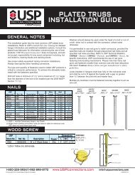
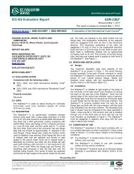
Laminated Beam Seats – KGLB, KGLBT, & KHGLB series<br />
Concrete & Masonry<br />
KGLB – Single bolt, bearing only.<br />
KGLBT – Double bolt with Structural Tee provides uplift and horizontal resistance.<br />
KHGLB – Double bolt design provides uplift and horizontal resistance.<br />
Materials: Flanges – 1/4˝ steel<br />
Bearing Plate – See chart<br />
Anchor dowels – 3⁄4˝ x 12˝ rebar<br />
Finish: <strong>USP</strong> primer<br />
Options: Consult <strong>USP</strong> for non-catalogue variations.<br />
Codes: Load values are derived from data<br />
submitted to various North American<br />
building code evaluators.<br />
Installation:<br />
• Use all specified fasteners. See Product<br />
Notes, page 10.<br />
• Bolt holes shall be a minimum of 1⁄ 32˝ to a<br />
maximum of 1⁄ 16˝ larger than the bolt diameter.<br />
• Concrete or masonry walls must be checked<br />
by a design professional for adequacy to resist<br />
lateral or uplift loads transferred from the beam<br />
seat anchor.<br />
<strong>USP</strong><br />
Stock<br />
No.<br />
Dimensions (in) Bolt Schedule Factored Bearing Resistance 1,4,5<br />
Masonry @ 375 psi 2 Concrete 3<br />
Dia.<br />
Ref. No. W L T D Qty<br />
(in)<br />
Lbs kN Lbs kN<br />
KGLB5A GLB5A 5-1/4 7 1/4 5 1 5/8 16980 75.53 16980 75.53<br />
KGLB5B GLB5B 5-1/4 7 3/8 6 1 5/8 20370 90.61 20370 90.61<br />
KGLB5C GLB5C 5-1/4 7 3/8 7 1 5/8 23765 105.72 23765 105.72<br />
KGLB5D GLB5D 5-1/4 7 3/8 8 1 5/8 27160 120.82 27160 120.82<br />
KGLB7A GLB7A 6-7/8 9 1/4 5 1 3/4 22355 99.44 22355 99.44<br />
KGLB7B GLB7B 6-7/8 9 3/8 6 1 3/4 26825 119.33 26825 119.33<br />
KGLB7C GLB7C 6-7/8 9 3/8 7 1 3/4 31300 139.23 31300 139.23<br />
KGLB7D GLB7D 6-7/8 9 3/8 8 1 3/4 35770 159.12 35770 159.12<br />
1) Beams must fully bear on plates.<br />
2) Factored bearing resistances are based on the bearing value listed times the bearing area equal to W x D. (Note that full<br />
bearing plate area is not used.) Factored bearing resistances shall be reduced where limited by wood bearing on the plate.<br />
3) Factored bearing resistances on concrete are based on factored wood bearing stress perpendicular to the grain of 460 psi<br />
and actual beam width times beam bearing length.<br />
4) Designer shall specify minimum edge and spacing requirements in masonry or concrete structure.<br />
5) Concrete or masonry support structure is assumed adequate to support loads listed.<br />
<strong>USP</strong><br />
Stock No.<br />
KHGLBA<br />
KHGLBB<br />
KHGLBC<br />
KHGLBD<br />
KGLBT512<br />
KGLBT612<br />
KGLBT516<br />
KGLBT616<br />
KGLBT520<br />
KGLBT620<br />
T<br />
L<br />
3˝<br />
3 1 /2˝<br />
KGLB<br />
W<br />
D<br />
12˝<br />
Bearing Plate<br />
Concrete pilaster<br />
Rebar welded to<br />
bearing plate<br />
Dimensions (in)<br />
Bolt<br />
Factored Bearing Resistance 1,5<br />
Schedule<br />
Masonry On Concrete with Beam Width 1 F2 3,4 Min. 3-1/8<br />
Range<br />
Dia.<br />
@<br />
Beam Width (W)<br />
Ref. No. W D L T Qty (in) Unit 375 psi 5-1/8 6-3/4 8-3/4 10-3/4 100% Uplift 115% 3<br />
HGLBA<br />
HGLBB<br />
HGLBC<br />
HGLBD<br />
GLBT512<br />
GLBT612<br />
GLBT516<br />
GLBT616<br />
GLBT520<br />
GLBT620<br />
3-1/4 to 9<br />
3-1/4 to 9<br />
3-1/4 to 9<br />
3-1/4 to 9<br />
3-1/4 to 11<br />
3-1/4 to 11<br />
3-1/4 to 15<br />
3-1/4 to 15<br />
3-1/4 to 19<br />
3-1/4 to 19<br />
5<br />
6<br />
7<br />
8<br />
5-1/2<br />
6-1/2<br />
5-1/2<br />
6-1/2<br />
5-1/2<br />
6-1/2<br />
10<br />
10<br />
10<br />
10<br />
12<br />
12<br />
16<br />
16<br />
20<br />
20<br />
3/8<br />
3/8<br />
3/8<br />
3/8<br />
1/3<br />
3/8<br />
1/3<br />
3/8<br />
1/3<br />
3/8<br />
2<br />
2<br />
2<br />
2<br />
2<br />
2<br />
2<br />
2<br />
2<br />
2<br />
3/4<br />
3/4<br />
3/4<br />
3/4<br />
3/4<br />
3/4<br />
3/4<br />
3/4<br />
3/4<br />
3/4<br />
Lbs<br />
Lbs<br />
Lbs<br />
Lbs<br />
Lbs<br />
Lbs<br />
Lbs<br />
Lbs<br />
Lbs<br />
Lbs<br />
27000<br />
32400<br />
37800<br />
43200<br />
35640<br />
42120<br />
39170<br />
46290<br />
39170<br />
46290<br />
16980<br />
20370<br />
23765<br />
27160<br />
18670<br />
22070<br />
18670<br />
22070<br />
18670<br />
22070<br />
22355<br />
26825<br />
31300<br />
35770<br />
24595<br />
29065<br />
24595<br />
29065<br />
24595<br />
29065<br />
28980<br />
34775<br />
40570<br />
46370<br />
31880<br />
37680<br />
31880<br />
37680<br />
31880<br />
37680<br />
-- --<br />
-- --<br />
-- --<br />
-- --<br />
39170<br />
46290<br />
39170<br />
46290<br />
39170<br />
46290<br />
9445<br />
9445<br />
9445<br />
9445<br />
9445<br />
9445<br />
9445<br />
9445<br />
9445<br />
9445<br />
4045<br />
4045<br />
4045<br />
4045<br />
4045<br />
4045<br />
4045<br />
4045<br />
4045<br />
4045<br />
kN<br />
kN<br />
kN<br />
kN<br />
kN<br />
kN<br />
kN<br />
kN<br />
kN<br />
kN<br />
120.11<br />
144.13<br />
168.15<br />
192.17<br />
158.54<br />
187.37<br />
174.24<br />
205.92<br />
174.24<br />
205.92<br />
75.53<br />
90.61<br />
105.72<br />
120.82<br />
83.05<br />
98.18<br />
83.05<br />
98.18<br />
83.05<br />
98.18<br />
99.44<br />
119.33<br />
139.23<br />
159.12<br />
109.41<br />
129.29<br />
109.41<br />
129.29<br />
109.41<br />
129.29<br />
128.91<br />
154.69<br />
180.47<br />
206.27<br />
141.81<br />
167.62<br />
141.81<br />
167.62<br />
141.81<br />
167.62<br />
-- --<br />
-- --<br />
-- --<br />
-- --<br />
174.24<br />
205.92<br />
174.24<br />
205.92<br />
174.24<br />
205.92<br />
42.02<br />
42.02<br />
42.02<br />
42.02<br />
42.02<br />
42.02<br />
42.02<br />
42.02<br />
42.02<br />
42.02<br />
17.99<br />
17.99<br />
17.99<br />
17.99<br />
17.99<br />
17.99<br />
17.99<br />
17.99<br />
17.99<br />
17.99<br />
1) Beams must fully bear on plates.<br />
2) Factored bearing resistances on concrete are based on factored bearing stress perpendicular to the grain of 460 psi and<br />
actual beam width times beam bearing length.<br />
3) The 115% values are short-term loads such as wind and earthquake and are based on bolt in wood values only.<br />
Factored resistances assume concrete or masonry structure is adequate to resist loads in those directions.<br />
4) Factored resistances must be be reduced if the allowable lateral load (F2) for masonry or concrete column governs.<br />
5) Designer shall specify minimum edge and spacing requirements in masonry or concrete structure.<br />
1/2˝ Min.<br />
clearance<br />
Uplift<br />
F2<br />
Typical KGLB installation<br />
D<br />
L<br />
3˝<br />
L<br />
3 1 /2˝<br />
1 1 /2˝<br />
3˝<br />
2 1 /2˝<br />
1 1 /2˝<br />
W<br />
Structural<br />
tee<br />
KGLBT<br />
W<br />
2 1 /2˝<br />
KHGLB<br />
1 1 /4˝<br />
T<br />
1 1 /4˝<br />
D<br />
T<br />
3˝<br />
4˝ 12˝<br />
3˝<br />
© Copyright 2013 <strong>USP</strong> Structural <strong>Connectors</strong> ®<br />
36<br />
1-800-328-5934 • www.<strong>USP</strong>connectors.com