Hangers - USP Connectors
Hangers - USP Connectors Hangers - USP Connectors
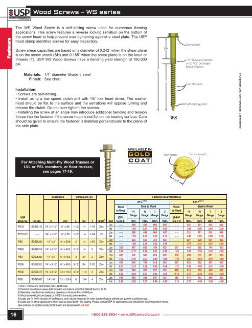
Wood Screws – WS series Fasteners The WS Wood Screw is a self-drilling screw used for numerous framing applications. This screw features a reverse locking serration on the bottom of the screw head to help prevent over tightening against a steel plate. The USP head stamp identifies screws for easy inspection. Screw shear capacities are based on a diameter of 0.242˝ when the shear plane is on the screw shank (SH) and 0.185˝ when the shear plane is on the knurl or threads (T). USP WS Wood Screws have a bending yield strength of 180,000 psi. Materials: Finish: 1/4˝ diameter Grade 5 steel See chart Installation: • Screws are self-drilling. • Install using a low speed clutch drill with 3/8˝ hex head driver. The washer head should be flat to the surface and the serrations will oppose turning and release the clutch. Do not over-tighten the screws. • Installing the screw at an angle may introduce additional bending and tension forces into the fastener if the screw head is not flat on the bearing surface. Care should be given to ensure the fastener is installed perpendicular to the plane of the side plate. L SH T WS Serrations 1/4˝ Beveled reamer on 2 1 /2˝ or longer Wood Screws Cut threads Self drilling point © Copyright 2013 USP Structural Connectors® USP name Screw length For Attaching Multi-Ply Wood Trusses or LVL or PSL members, or floor trusses, see pages 17-19. 3/8˝ USP Stock No. WS15 WS15-GC WS2 WS25 WS3 WS35 WS45 WS6 Description Dimensions (in) Wood to Wood Factored Shear Resistance 14 10 7 3 10 7 3 (DF-L Gauge Gauge Gauge Gauge (S-P-F Gauge Gauge Gauge Gauge Ref. No. in mm L SH T Finish 1 Unit to DF-L) 100% 100% 100% 100% to S-P-F) 100% 100% 100% 100% SDS25112 -- -- SDS25200 SDS25212 SDS25300 SDS25312 SDS25412 SDS25600 6.1 x 38 6.1 x 38 6.1 x 50.8 6.1 x 63.5 6.1 x 76.2 6.1 x 88.9 6.1 x 114.3 6.1 x 152.4 1-1/2 1-1/2 2 2-1/2 3 3-1/2 4-1/2 6 1/4 1/4 1/4 1/4 3/4 3/4 1-1/4 1-3/4 1-1/4 1-1/4 1-3/4 2 2 2-1/2 3 4 Zinc GC Zinc Zinc Zinc Zinc Zinc Zinc Lbs Lbs Lbs Lbs Lbs Lbs Lbs Lbs -- -- -- -- -- -- 323 387 452 543 543 358 358 423 487 552 616 680 680 496 496 561 625 690 754 825 825 660 660 724 789 853 918 997 997 807 807 1031 1031 1031 1031 1031 1031 -- -- -- -- -- -- 277 332 387 480 480 332 332 387 443 498 553 618 618 471 471 526 582 637 692 763 763 635 635 691 746 801 857 890 890 692 692 900 900 900 900 900 900 kN kN kN kN kN kN kN kN -- -- -- -- -- -- 1.44 1.72 2.01 2.42 2.42 1.59 1.59 1.88 2.17 2.46 2.74 3.02 3.02 2.21 2.21 2.49 2.78 3.07 3.36 3.67 3.67 2.93 2.93 3.22 3.51 3.80 4.08 4.44 4.44 3.59 3.59 4.58 4.58 4.58 4.58 4.58 4.58 -- -- -- -- -- -- 1.23 1.48 1.72 2.14 2.14 1.48 1.48 1.72 1.97 2.21 2.46 2.75 2.75 2.09 2.09 2.34 2.59 2.83 3.08 3.40 3.40 2.83 2.83 3.07 3.32 3.56 3.81 3.96 3.96 3.08 3.08 4.00 4.00 4.00 4.00 4.00 4.00 DF-L 2,3,4,5 Steel to Wood 1) Zinc = Yellow zinc dichromate; GC = Gold Coat. 2) Factored Resistance values determined in accordance with CSA O86-09 Section 10.11. 3) Steel side plate factored resistance based on a minimum Fu = 45,000 psi. 5) Loads are for 100% duration of load factors, and may be increased for other duration factors allowed per governing building code. 6) Loads are for shear applications when used as described in this catalog. Please contact USP for applications and installations involving tension forces. New products or updated product information are designated in red font. Wood to Wood 14 S-P-F 2,3,4,5 Steel to Wood 16 1-800-328-5934 • www.USPconnectors.com
Wood Screw Applications – WS series Joining 2, 3, or 4 Ply Wood Trusses © Copyright 2013 USP Structural Connectors® The installation instructions and design example shown below are intended for a design professional who will be responsible for determining the location and number of wood screws to adequately transfer all loads on the truss. Installation: • Screw spacing shall not be greater than 24˝ on centre and less than 4˝ on centre. However, the location of any individual screw may be adjusted up to one-half the required screw spacing to avoid lumber defects or interference with other hardware. • Load or hanger spacing shall not be greater than 24˝ centre-to-centre. • The last truss ply must have a minimum of 11/4˝ of screw penetration and no more than 1/8˝ gap between each ply. • Screws cannot be installed through metal truss plates unless the Truss Engineer approves predrilling. • On 2x4 members, use one row of wood screws. On 2x6 and 2x8 use two rows, and on 2x10 use three rows. Stagger all rows. • The truss bottom chord shall have lateral bracing installed as called out by the Truss Engineer to prevent any displacement from torsional forces. • Install screws from one side without flipping the truss. • Top and bottom chords require screws and in some cases the webs may require screws. • All lateral bracing should be attached to each truss ply. • Increase edge and end distances if wood splitting occurs. 2 1 /2˝ Min. 1 1 /2˝ Min. Start screws on face that carries hanger on load Spacing 4˝ min. – 24˝ max. 1˝ min. Recommended (Typ) Spacing 4˝ min. – 24˝ max. 4˝ min 1 1 /2˝ Min. End of chord Fasteners Description Length (in) Factored Shear Loads (100%.) 1,2,3 Shear S-P-F USP Plane DF-L Stock No. Ref. No. in mm L SH T Finish Location Lbs kN Lbs kN WS3 SDS25300 3 3/4 2 Zinc SH, T 387 1.72 332 1.48 WS45 SDS25412 3 Zinc SH, T 543 2.42 480 2.14 WS6 SDS25600 6 4 Zinc SH, T 543 2.42 480 2.14 2) The Truss Engineer shall apply all applicable adjustment factors. New products or updated product information are designated in red font. 3 Ply with Mixed Wood Species: Bottom Chord: 2x6 Douglas Fir-Larch Top Chord: 2x4 Spruce-Pine-Fir WS45 Wood Screw Factored Resistance: (Assume shear plane across the screw shank) Douglas Fir-Larch: 543 Ibs. each at 100% Spruce-Pine-Fir: 480 lbs. each at 100% Design Example Truss top chord Required Loads: Bottom Chord Load: 500 plf Top Chord Load: 60 plf Bottom Chord Wood Screw Spacing: Using 2 rows of WS45 Wood Screws in 2x6 2 x 543/500 x # Plies = 3.26 ft. # Plies - 1 Use maximum spacing of 24˝. Top Chord Wood Screw Spacing: Only 1 row of WS45 Wood Screws in 2x4 member 1 x 480/60 x # Plies = 12.0 ft. # Plies - 1 Use maximum spacing of 24˝. Truss bottom chord Truss span Typical Truss Profile (profile may vary) continued on next page 1-800-328-5934 • www.USPconnectors.com 17 USP2240-131
- Page 1 and 2: Product Catalog 57 th Edition
- Page 3 and 4: The Original Connector Company! HA
- Page 5 and 6: USP Index © Copyright 2013 USP Str
- Page 7 and 8: Corrosion Information © Copyright
- Page 9 and 10: Product Information U.S. Standard S
- Page 11 and 12: Design Notes © Copyright 2013 USP
- Page 13 and 14: Fasteners © Copyright 2013 USP Str
- Page 15: Nails - N & NA series continued NA1
- Page 19 and 20: Wood Screw Applications - WS series
- Page 21 and 22: Concrete & Masonry © Copyright 201
- Page 23 and 24: ADHESIVE ANCHORING SYSTEMS CIA-GEL
- Page 25 and 26: Undercut Anchoring Systems - DUC Du
- Page 27 and 28: Steel Angle Lintels - SAL series St
- Page 29 and 30: Threaded Rods - THR series USP has
- Page 31 and 32: Anchor Bolts - STB & STBL series Em
- Page 33 and 34: Anchor Bolts - AB & ABP series Anch
- Page 35 and 36: Foundation Anchors - ST series ST1-
- Page 37 and 38: Adjustable Support Posts - JP serie
- Page 39 and 40: Type 2 Top Plates - T2TP Series ©
- Page 41 and 42: Predeflected Holdowns - PHD & PHDA
- Page 43 and 44: Holdowns - TD & TDX series continue
- Page 45 and 46: Tension Ties - HTT, LTS series & LT
- Page 47 and 48: Foundation Straps - LSTAD & STAD Se
- Page 49 and 50: Foundation Straps - HPAHD & PAHD42
- Page 51 and 52: Caps & Bases Post Anchors . . . . .
- Page 53 and 54: Wet Post Anchors - WAS & WE series
- Page 55 and 56: © Copyright 2013 USP Structural Co
- Page 57 and 58: Post Caps - EPCM & PCM series © Co
- Page 59 and 60: Post Beam Corner - PBC series The P
- Page 61 and 62: Column Caps - KCCQ & KECCQ series c
- Page 63 and 64: Column Caps - KCCQ & KECCQ series c
- Page 65 and 66: Angles & Straps Coiled Strapping .
Wood Screws – WS series<br />
Fasteners<br />
The WS Wood Screw is a self-drilling screw used for numerous framing<br />
applications. This screw features a reverse locking serration on the bottom of<br />
the screw head to help prevent over tightening against a steel plate. The <strong>USP</strong><br />
head stamp identifies screws for easy inspection.<br />
Screw shear capacities are based on a diameter of 0.242˝ when the shear plane<br />
is on the screw shank (SH) and 0.185˝ when the shear plane is on the knurl or<br />
threads (T). <strong>USP</strong> WS Wood Screws have a bending yield strength of 180,000<br />
psi.<br />
Materials:<br />
Finish:<br />
1/4˝ diameter Grade 5 steel<br />
See chart<br />
Installation:<br />
• Screws are self-drilling.<br />
• Install using a low speed clutch drill with 3/8˝ hex head driver. The washer<br />
head should be flat to the surface and the serrations will oppose turning and<br />
release the clutch. Do not over-tighten the screws.<br />
• Installing the screw at an angle may introduce additional bending and tension<br />
forces into the fastener if the screw head is not flat on the bearing surface. Care<br />
should be given to ensure the fastener is installed perpendicular to the plane of<br />
the side plate.<br />
L<br />
SH<br />
T<br />
WS<br />
Serrations<br />
1/4˝ Beveled reamer<br />
on 2 1 /2˝ or longer<br />
Wood Screws<br />
Cut threads<br />
Self drilling point<br />
© Copyright 2013 <strong>USP</strong> Structural <strong>Connectors</strong>®<br />
<strong>USP</strong> name<br />
Screw length<br />
For Attaching Multi-Ply Wood Trusses or<br />
LVL or PSL members, or floor trusses,<br />
see pages 17-19.<br />
3/8˝<br />
<strong>USP</strong><br />
Stock No.<br />
WS15<br />
WS15-GC<br />
WS2<br />
WS25<br />
WS3<br />
WS35<br />
WS45<br />
WS6<br />
Description<br />
Dimensions (in)<br />
Wood<br />
to Wood<br />
Factored Shear Resistance<br />
14 10 7 3<br />
10 7 3<br />
(DF-L<br />
Gauge Gauge Gauge Gauge<br />
(S-P-F<br />
Gauge Gauge Gauge Gauge<br />
Ref. No. in mm L SH T Finish 1 Unit to DF-L) 100% 100% 100% 100% to S-P-F) 100% 100% 100% 100%<br />
SDS25112<br />
-- --<br />
SDS25200<br />
SDS25212<br />
SDS25300<br />
SDS25312<br />
SDS25412<br />
SDS25600<br />
<br />
<br />
<br />
<br />
<br />
<br />
<br />
<br />
6.1 x 38<br />
6.1 x 38<br />
6.1 x 50.8<br />
6.1 x 63.5<br />
6.1 x 76.2<br />
6.1 x 88.9<br />
6.1 x 114.3<br />
6.1 x 152.4<br />
1-1/2<br />
1-1/2<br />
2<br />
2-1/2<br />
3<br />
3-1/2<br />
4-1/2<br />
6<br />
1/4<br />
1/4<br />
1/4<br />
1/4<br />
3/4<br />
3/4<br />
1-1/4<br />
1-3/4<br />
1-1/4<br />
1-1/4<br />
1-3/4<br />
2<br />
2<br />
2-1/2<br />
3<br />
4<br />
Zinc<br />
GC<br />
Zinc<br />
Zinc<br />
Zinc<br />
Zinc<br />
Zinc<br />
Zinc<br />
Lbs<br />
Lbs<br />
Lbs<br />
Lbs<br />
Lbs<br />
Lbs<br />
Lbs<br />
Lbs<br />
-- --<br />
-- --<br />
-- --<br />
323<br />
387<br />
452<br />
543<br />
543<br />
358<br />
358<br />
423<br />
487<br />
552<br />
616<br />
680<br />
680<br />
496<br />
496<br />
561<br />
625<br />
690<br />
754<br />
825<br />
825<br />
660<br />
660<br />
724<br />
789<br />
853<br />
918<br />
997<br />
997<br />
807<br />
807<br />
1031<br />
1031<br />
1031<br />
1031<br />
1031<br />
1031<br />
-- --<br />
-- --<br />
-- --<br />
277<br />
332<br />
387<br />
480<br />
480<br />
332<br />
332<br />
387<br />
443<br />
498<br />
553<br />
618<br />
618<br />
471<br />
471<br />
526<br />
582<br />
637<br />
692<br />
763<br />
763<br />
635<br />
635<br />
691<br />
746<br />
801<br />
857<br />
890<br />
890<br />
692<br />
692<br />
900<br />
900<br />
900<br />
900<br />
900<br />
900<br />
kN<br />
kN<br />
kN<br />
kN<br />
kN<br />
kN<br />
kN<br />
kN<br />
-- --<br />
-- --<br />
-- --<br />
1.44<br />
1.72<br />
2.01<br />
2.42<br />
2.42<br />
1.59<br />
1.59<br />
1.88<br />
2.17<br />
2.46<br />
2.74<br />
3.02<br />
3.02<br />
2.21<br />
2.21<br />
2.49<br />
2.78<br />
3.07<br />
3.36<br />
3.67<br />
3.67<br />
2.93<br />
2.93<br />
3.22<br />
3.51<br />
3.80<br />
4.08<br />
4.44<br />
4.44<br />
3.59<br />
3.59<br />
4.58<br />
4.58<br />
4.58<br />
4.58<br />
4.58<br />
4.58<br />
-- --<br />
-- --<br />
-- --<br />
1.23<br />
1.48<br />
1.72<br />
2.14<br />
2.14<br />
1.48<br />
1.48<br />
1.72<br />
1.97<br />
2.21<br />
2.46<br />
2.75<br />
2.75<br />
2.09<br />
2.09<br />
2.34<br />
2.59<br />
2.83<br />
3.08<br />
3.40<br />
3.40<br />
2.83<br />
2.83<br />
3.07<br />
3.32<br />
3.56<br />
3.81<br />
3.96<br />
3.96<br />
3.08<br />
3.08<br />
4.00<br />
4.00<br />
4.00<br />
4.00<br />
4.00<br />
4.00<br />
DF-L 2,3,4,5<br />
Steel to Wood<br />
1) Zinc = Yellow zinc dichromate; GC = Gold Coat.<br />
2) Factored Resistance values determined in accordance with CSA O86-09 Section 10.11.<br />
3) Steel side plate factored resistance based on a minimum Fu = 45,000 psi.<br />
<br />
5) Loads are for 100% duration of load factors, and may be increased for other duration factors allowed per governing building code.<br />
6) Loads are for shear applications when used as described in this catalog. Please contact <strong>USP</strong> for applications and installations involving tension forces.<br />
New products or updated product information are designated in red font.<br />
Wood<br />
to Wood 14<br />
S-P-F 2,3,4,5<br />
Steel to Wood<br />
16<br />
1-800-328-5934 • www.<strong>USP</strong>connectors.com


