MANUFACTURING TOLERANCES - harley-davidson-sweden.se
MANUFACTURING TOLERANCES - harley-davidson-sweden.se
MANUFACTURING TOLERANCES - harley-davidson-sweden.se

You also want an ePaper? Increase the reach of your titles
YUMPU automatically turns print PDFs into web optimized ePapers that Google loves.
HOME<br />
SPECIFICATIONS 3.1<br />
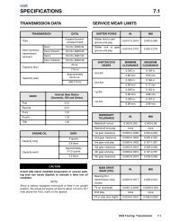
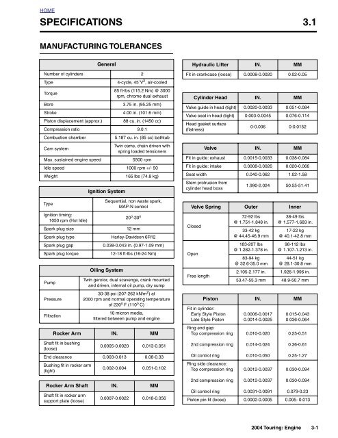
<strong>MANUFACTURING</strong> <strong>TOLERANCES</strong><br />
General<br />
Number of cylinders 2<br />
Type<br />
4-cycle, 45˚V 2 , air-cooled<br />
Torque<br />
85 ft-lbs (115.2 Nm) @ 3000<br />
rpm, chrome dual exhaust<br />
Bore<br />
3.75 in. (95.25 mm)<br />
Stroke<br />
4.00 in. (101.6 mm)<br />
Piston displacement (approx.) 88 cu. in. (1450 cc)<br />
Compression ratio 9.0:1<br />
Hydraulic Lifter IN. MM<br />
Fit in crankca<strong>se</strong> (loo<strong>se</strong>) 0.0008-0.0020 0.02-0.05<br />
Cylinder Head IN. MM<br />
Valve guide in head (tight) 0.0020-0.0033 0.051-0.084<br />
Valve <strong>se</strong>at in head (tight) 0.003-0.0045 0.076-0.114<br />
Head gasket surface<br />
(flatness)<br />
0-0.006 0-0.0152<br />
Combustion chamber<br />
5.187 cu. in. (85 cc) bathtub<br />
Cam system<br />
Twin cams, chain driven with<br />
spring loaded tensioners<br />
Max. sustained engine speed<br />
5500 rpm<br />
Idle speed 1000 rpm +/- 50<br />
Weight<br />
165 lbs (74.8 kg)<br />
Type<br />
Ignition timing:<br />
1050 rpm (Hot Idle)<br />
Spark plug size<br />
Spark plug type<br />
Spark plug gap<br />
Spark plug torque<br />
Pump<br />
Ignition System<br />
Sequential, non waste spark,<br />
MAP-N control<br />
20 o -30 o<br />
12 mm<br />
Harley-Davidson 6R12<br />
0.038-0.043 in. (0.97-1.09 mm)<br />
12-18 ft-lbs (16-24 Nm)<br />
Oiling System<br />
Twin gerotor, dual scavenge, crank mounted<br />
and driven, internal oil pump, dry sump<br />
Valve IN. MM<br />
Fit in guide: exhaust 0.0015-0.0033 0.038-0.084<br />
Fit in guide: intake 0.0008-0.0026 0.020-0.066<br />
Seat width 0.040-0.062 1.02-1.58<br />
Stem protrusion from<br />
cylinder head boss<br />
1.990-2.024 50.55-51.41<br />
Valve Spring Outer Inner<br />
Clo<strong>se</strong>d<br />
Open<br />
Free length<br />
72-92 lbs<br />
@ 1.751-1.848 in.<br />
33-42 kg<br />
@ 44.45-46.9 mm<br />
183-207 lbs<br />
@ 1.282-1.378 in.<br />
83-94 kg<br />
@ 32.6-35.0 mm<br />
38-49 lbs<br />
@ 1.577-1.683 in.<br />
17-22 kg<br />
@ 40.1-42.8 mm<br />
98-112 lbs<br />
@ 1.107-1.213 in.<br />
44-51 kg<br />
@ 28.1-30.8 mm<br />
2.105-2.177 in. 1.926-1.996 in.<br />
53.47-55.3 mm 48.9-50.7 mm<br />
Pressure<br />
Filtration<br />
30-38 psi (207-262 kN/m 2 ) at<br />
2000 rpm and normal operating temperature<br />
of 230 o F (110 o C)<br />
10 micron media,<br />
filtered between pump and engine<br />
Piston IN. MM<br />
Fit in cylinder:<br />
Early Style Piston<br />
Late Style Piston<br />
0.0006-0.0017<br />
0.0014-0.0025<br />
0.015-0.043<br />
0.036-0.064<br />
Rocker Arm IN. MM<br />
Ring end gap:<br />
Top compression ring<br />
0.010-0.020<br />
0.25-0.51<br />
Shaft fit in bushing<br />
(loo<strong>se</strong>)<br />
0.0005-0.0020 0.013-0.051<br />
2nd compression ring<br />
0.014-0.024<br />
0.36-0.61<br />
End clearance 0.003-0.013 0.08-0.33<br />
Oil control ring<br />
0.010-0.050<br />
0.25-1.27<br />
Bushing fit in rocker arm<br />
(tight)<br />
0.002-0.004 0.051-0.102<br />
Ring side clearance:<br />
Top compression ring<br />
0.0012-0.0037<br />
0.030-0.094<br />
Rocker Arm Shaft IN. MM<br />
Shaft fit in rocker arm<br />
support plate (loo<strong>se</strong>)<br />
0.0007-0.0022 0.018-0.056<br />
2nd compression ring 0.0012-0.0037 0.030-0.094<br />
Oil control ring<br />
0.0031-0.0091 0.079-0.23<br />
Piston pin fit (loo<strong>se</strong>) 0.0002-0.0005 0.005- 0.013<br />
2004 Touring: Engine 3-1
HOME<br />
<strong>MANUFACTURING</strong> <strong>TOLERANCES</strong> (CONT.)<br />
Connecting Rod IN. MM<br />
Piston pin fit (loo<strong>se</strong>) 0.0007-0.0012 0.018-0.030<br />
Side play between<br />
flywheels<br />
0.005-0.015 0.13-0.38<br />
Connecting rod to<br />
crankpin (loo<strong>se</strong>)<br />
0.0004-0.0017 0.0102-0.0432<br />
Flywheel IN. MM<br />
Runout<br />
(flywheels at rim)<br />
0.000-0.010 0.000-0.254<br />
Runout<br />
(shaft at flywheel)<br />
0.000-0.002 0.000-0.051<br />
End play 0.003-0.010 0.076-0.254<br />
Crankshaft/Sprocket<br />
Shaft Bearings<br />
IN.<br />
MM<br />
Bearing fit (loo<strong>se</strong>) 0.0002-0.0015 0.005-0.038<br />
Crankshaft runout 0.0-0.003 0.0-0.076<br />
Bearing fit in<br />
crankca<strong>se</strong> (tight)<br />
0.0038-0.0054 0.097-0.137<br />
Bearing inner race on<br />
crankshaft (tight)<br />
0.0004-0.0014 0.010-0.036<br />
TORQUE VALUES<br />
Item ft/in-lbs NM<br />
Breather as<strong>se</strong>mbly bolts 90-120 in-lbs 10-14 Nm<br />
Cam cover screws 125-155 in-lbs 14-18 Nm<br />
Cam cover plate screws 20-30 in-lbs 2.3-3.4 Nm<br />
Cam support plate screws 90-120 in-lbs 10-14 Nm<br />
Bearing retainer plate<br />
screws<br />
20-30 in-lbs 2-3 Nm<br />
Crank sprocket flange bolt<br />
Primary cam sprocket<br />
flange bolt<br />
15 ft-lbs,<br />
loo<strong>se</strong>n one full<br />
turn, 24 ft-lbs<br />
15 ft-lbs,<br />
loo<strong>se</strong>n one full<br />
turn, 34 ft-lbs<br />
20.3 Nm,<br />
loo<strong>se</strong>n one full<br />
turn, 32.5 Nm<br />
20.3 Nm,<br />
loo<strong>se</strong>n one<br />
full turn, 46.1<br />
Nm<br />
Crank position <strong>se</strong>nsor<br />
screw<br />
90-120 in-lbs 10.2-13.6 Nm<br />
Piston jet screws 25-35 in-lbs 2.8-4.0 Nm<br />
Transmission housing to<br />
crankca<strong>se</strong> bolts<br />
Crankca<strong>se</strong> to front engine<br />
mounting bracket bolts<br />
Crankca<strong>se</strong> bolts<br />
Cylinder head bolts<br />
15 ft-lbs,<br />
30-35 ft-lbs<br />
20 Nm,<br />
41-48 Nm<br />
33-38 ft-lbs 45-52 Nm<br />
10 ft-lbs,<br />
15-19 ft-lbs<br />
120-144 in-lbs,<br />
15-17 ft-lbs<br />
+ 90 o turn<br />
14 Nm,<br />
20-26 Nm<br />
13.6-16.3 Nm,<br />
20.3-23.1 Nm<br />
+ 90 o turn<br />
Cylinder studs 10-20 ft-lbs 14-27 Nm<br />
Engine oil drain plug 14-21 ft-lbs 19-28 Nm<br />
Lifter cover screws 90-120 in-lbs 10-14 Nm<br />
Oil pan screws 84-108 in-lbs 9-12 Nm<br />
Oil filter<br />
1/2-3/4 turn after gasket contact<br />
Oil filter mount 12-16 ft-lbs 16-22 Nm<br />
Crankca<strong>se</strong> oil fittings/plugs 120-168 in-lbs 13.6-18.9 Nm<br />
Oil ho<strong>se</strong> cover screws 84-108 in-lbs 10-12 Nm<br />
Oil pressure switch/<strong>se</strong>nder 96-120 in-lbs 11-14 Nm<br />
Rocker arm support<br />
plate bolts<br />
18-22 ft-lbs 24-30 Nm<br />
Rocker cover bolts 15-18 ft-lbs 20-24 Nm<br />
Rocker housing bolts 120-168 in-lbs 13.6-18.9 Nm<br />
Spark plugs 12-18 ft-lbs 16-24 Nm<br />
Stator screws 55-75 in-lbs 6.2-8.5 Nm<br />
Upper engine mounting<br />
bracket:<br />
To cylinder heads<br />
To top stabilizer link<br />
Engine temperature<br />
<strong>se</strong>nsor<br />
Intake flange adapter<br />
screws<br />
Exhaust flange adapter<br />
nuts<br />
35-40 ft-lbs<br />
18-22 ft-lbs<br />
48-54 Nm<br />
24-30 Nm<br />
120-180 in-lbs 13.6-20.3 Nm<br />
96-144 in-lbs 10.9-16.3 Nm<br />
100-120 in-lbs 11.3-13.6 Nm<br />
3-2 2004 Touring: Engine
HOME<br />
SERVICE WEAR LIMITS 3.2<br />
GENERAL<br />
Wear limits can be u<strong>se</strong>d as a guide when deciding whether to<br />
reu<strong>se</strong> engine parts. Replace u<strong>se</strong>d parts whenever the following<br />
wear limits are exceeded.<br />
REPLACE IF<br />
Cylinder Bore<br />
IN.<br />
MM<br />
Standard More than 3.752 More than 95.301<br />
Rocker Arm/<br />
Rocker Arm Shaft<br />
IN.<br />
REPLACE IF<br />
MM<br />
0.005 in. oversize More than 3.757 More than 95.428<br />
0.010 in. oversize More than 3.762 More than 95.555<br />
Shaft fit in bushing (loo<strong>se</strong>) More than 0.0035 More than 0.089<br />
End clearance More than 0.025 More than 0.635<br />
Shaft fit in rocker arm<br />
support plate (loo<strong>se</strong>)<br />
More than 0.0035 More than 0.089<br />
REPLACE IF<br />
Piston<br />
IN.<br />
MM<br />
Fit in cylinder (loo<strong>se</strong>) More than 0.003 More than 0.076<br />
Hydraulic Lifter<br />
IN.<br />
REPLACE IF<br />
MM<br />
Piston pin fit (loo<strong>se</strong>) More than 0.0008 More than 0.020<br />
Ring end gap<br />
Top compression More than 0.030 More than 0.76<br />
2nd compression More than 0.034 More than 0.86<br />
Fit in crankca<strong>se</strong> More than 0.003 More than 0.08<br />
Roller fit More than 0.0015 More than 0.038<br />
Roller end clearance More than 0.015 More than 0.38<br />
Oil control ring rails More than 0.050 More than 1.27<br />
Ring side clearance<br />
Top compression More than 0.0045 More than 0.11<br />
2nd compression More than 0.0045 More than 0.11<br />
Cam Support Plate<br />
Cam chain<br />
tensioner shoe wear<br />
Crankshaft bushing fit<br />
in cam support plate<br />
Crankshaft bushing<br />
maximum ID<br />
REPLACE IF<br />
IN.<br />
MM<br />
More than 0.090 More than 2.29<br />
1/2 thickness of shoe<br />
Less than 0.0008 Less than 0.0203<br />
More than 0.8545 More than 21.704<br />
Oil control ring rails More than 0.010 More than 0.25<br />
Connecting Rod<br />
IN.<br />
REPLACE IF<br />
MM<br />
Piston pin fit (loo<strong>se</strong>) More than 0.002 More than 0.051<br />
Side play between<br />
flywheels<br />
More than 0.020 More than 0.508<br />
Fit on crankpin (loo<strong>se</strong>) More than 0.002 More than 0.051<br />
REPLACE IF<br />
Cylinder Head<br />
IN.<br />
MM<br />
Valve guide in head (tight) Less than 0.002 Less than 0.051<br />
Valve <strong>se</strong>at in head (tight) Less than 0.002 Less than 0.051<br />
Head warpage More than 0.006 More than 0.152<br />
REPLACE IF<br />
Flywheel<br />
IN.<br />
MM<br />
Runout (flywheels at rim) More than 0.015 More than 0.381<br />
Runout (shaft at flywheel) More than 0.003 More than 0.076<br />
End play More than 0.010 More than 0.254<br />
REPLACE IF<br />
Cylinder<br />
IN.<br />
MM<br />
Taper More than 0.002 More than 0.051<br />
Crankshaft/Sprocket<br />
Shaft Bearings<br />
Bearing to shaft<br />
clearance<br />
REPLACE IF<br />
IN.<br />
MM<br />
More than 0.0015 More than 0.038<br />
Out of round More than 0.002 More than 0.051<br />
Shaft runout More than 0.003 More than 0.076<br />
Warpage of gasket or<br />
O-ring surfaces: top<br />
More than 0.006 More than 0.152<br />
Bearing fit in<br />
crankca<strong>se</strong> (tight)<br />
Less than 0.0038 Less than 0.097<br />
Warpage of gasket or<br />
O-ring surfaces: ba<strong>se</strong><br />
More than 0.004 More than 0.102<br />
Bearing inner race<br />
on shaft (tight)<br />
Less than 0.0004 Less than 0.010<br />
2004 Touring: Engine 3-3
HOME<br />
SERVICE WEAR LIMITS (CONT.)<br />
Breather As<strong>se</strong>mbly<br />
IN.<br />
REPLACE IF<br />
MM<br />
Breather cover warpage More than 0.005 More than 0.13<br />
Breather baffle warpage More than 0.005 More than 0.13<br />
Valve Stem to<br />
Guide Clearance<br />
IN.<br />
REPLACE IF<br />
MM<br />
Intake More than 0.0035 More than 0.089<br />
Exhaust More than 0.0040 More than 0.102<br />
3-4 2004 Touring: Engine
HOME<br />
GENERAL INFORMATION 3.3<br />
FUEL<br />
U<strong>se</strong> a good quality leaded or unleaded gasoline (91 pump<br />
octane or higher). Octane rating is usually posted on the<br />
pump.<br />
CAUTION<br />
Using gasolines with alcohol additives (such as methanol)<br />
can cau<strong>se</strong> rubber components within the fuel system<br />
to fail or result in engine damage.<br />
GASOLINE/ALCOHOL BLENDS<br />
Harley-Davidson motorcycles were designed to give the best<br />
performance using unleaded gasoline. Some fuel suppliers<br />
<strong>se</strong>ll gasoline/alcohol blends as a fuel. The type and amount<br />
of alcohol added to the fuel is important.<br />
●<br />
●<br />
DO NOT USE GASOLINES CONTAINING METHANOL.<br />
Using gasoline/methanol blends will result in starting<br />
and driveablility deterioration and damage to critical fuel<br />
system components.<br />
ETHANOL is a mixture of 10% ethanol (Grain alcohol)<br />
and 90% unleaded gasoline. Gasoline/ethanol blends<br />
can be u<strong>se</strong>d in your motorcycle if the ethanol content<br />
does not exceed 10%.<br />
● REFORMULATED OR OXYGENATED GASOLINES<br />
(RFG): “Reformulated gasoline” is a term u<strong>se</strong>d to<br />
describe gasoline blends that are specifically designed<br />
to burn cleaner than other types of gasoline. Your motorcycle<br />
will run normally using this type of gas.<br />
You may find that some gasoline blends adver<strong>se</strong>ly affect the<br />
starting, driveability or fuel efficiency of your bike. If you<br />
experience one or more of the<strong>se</strong> problems, we recommend<br />
you try a different brand of gasoline or gasoline with a higher<br />
octane rating.<br />
LUBRICATION<br />
CHECKING ENGINE OIL LEVEL<br />
CAUTION<br />
Oil level cannot be accurately measured on a cold<br />
engine. For preride inspection, with motorcycle leaning<br />
on jiffy stand on level ground, oil should register on dipstick<br />
between arrows when engine is cold. Do NOT add<br />
oil to bring the level to the FULL mark on a COLD engine.<br />
1. Perform engine oil level COLD CHECK as follows:<br />
a. With the vehicle resting on the jiffy stand on level<br />
ground, wipe off the dipstick and in<strong>se</strong>rt it back into<br />
the oil pan with the plug pushed completely into the<br />
fill spout.<br />
b. Remove the dipstick and note the level of the oil. Oil<br />
level should register between the two arrows on the<br />
dipstick. See Figure 3-1. If oil level is at or below the<br />
lower arrow, add only enough oil to bring the level<br />
between the two arrows on the dipstick.<br />
2. Perform engine oil level HOT CHECK as follows:<br />
a. Ride vehicle until engine is at normal operating temperature.<br />
b. With the vehicle resting on the jiffy stand on level<br />
ground, allow engine to idle for 1-2 minutes. Turn<br />
engine off.<br />
c. Wipe off the dipstick and in<strong>se</strong>rt it back into the oil<br />
pan with the plug pushed completely into the fill<br />
spout.<br />
d. Remove the dipstick and note the level of the oil.<br />
Add only enough oil to bring the level to the FULL<br />
mark on the dipstick. See Figure 3-1. Do not overfill.<br />
COLD CHECK<br />
HOT CHECK<br />
f1254b3x<br />
Figure 3-1. Engine Oil Dipstick<br />
2004 Touring: Engine 3-5
HOME<br />
5. Remove the oil filter as follows:<br />
a. Obtain the OIL FILTER WRENCH (HD-42311). The<br />
tool allows easy removal of the oil filter without risk<br />
of damage to the crankshaft position <strong>se</strong>nsor or<br />
cable.<br />
b. Place the jaws of the wrench over the oil filter with<br />
the tool oriented vertically. See Figure 3-3.<br />
c. Using a 3/8 inch drive with a 4 inch extension, turn<br />
wrench in a counterclockwi<strong>se</strong> direction. Do not u<strong>se</strong><br />
with air tools.<br />
Figure 3-2. Oil Filter Wrench (Part No. HD-42311)<br />
f1641x3x<br />
NOTE<br />
U<strong>se</strong> OIL FILTER WRENCH (HD-44067) if HD-42311 is not<br />
available.<br />
6. Clean the oil filter mount flange of any old gasket material.<br />
7. Lubricate gasket with clean engine oil and install new oil<br />
filter on filter mount. Hand tighten oil filter 1/2-3/4 turn<br />
after gasket first contacts filter mounting surface. Do<br />
NOT u<strong>se</strong> OIL FILTER WRENCH for oil filter installation.<br />
NOTE<br />
U<strong>se</strong> of the Premium 10 micron synthetic media oil filter is<br />
highly recommended, Part No. 63798-99 (Chrome) or 63731-<br />
99 (Black).<br />
8. Install engine oil drain plug with O-ring. Tighten plug to<br />
14-21 ft-lbs (19-28 Nm).<br />
9. With vehicle resting on jiffy stand, add 3-1/2 quarts (3.3<br />
liters) engine oil as specified in Table 3-1. U<strong>se</strong> the proper<br />
grade of oil for the lowest temperature expected before<br />
the next oil change.<br />
Figure 3-3. Remove Engine Oil Filter<br />
Table 3-1. Recommended Engine Oils<br />
CHANGING ENGINE OIL AND FILTER<br />
NOTE<br />
Harley-Davidson<br />
Type<br />
Viscosity<br />
Harley-<br />
Davidson<br />
Rating<br />
Lowest<br />
Ambient<br />
Temperature<br />
Cold Weather<br />
Starts Below<br />
50˚F (10˚C)<br />
At the 1000 mile (1600 km) <strong>se</strong>rvice interval, and at every<br />
5000 mile (8000 km) <strong>se</strong>rvice interval thereafter, change the<br />
engine oil and engine oil filter. If motorcycle is ridden hard,<br />
under dusty conditions or in cold weather, change engine oil<br />
and filter more often.<br />
HD Multi-grade<br />
HD Multi-grade<br />
HD Regular Heavy<br />
SAE<br />
10W40<br />
SAE<br />
20W50<br />
SAE<br />
50<br />
HD 360<br />
HD 360<br />
HD 360<br />
Below 40˚F<br />
(4˚C)<br />
Above 40˚F<br />
(4˚C)<br />
Above 60˚F<br />
(16˚C)<br />
Excellent<br />
Good<br />
Poor<br />
1. Ride vehicle until engine is at normal operating temperature.<br />
HD Extra Heavy<br />
SAE<br />
60<br />
HD 360<br />
Above 80˚F<br />
(27˚C)<br />
Poor<br />
2. Locate oil filler plug/dipstick on right side of vehicle at top<br />
of transmission ca<strong>se</strong>. To remove the oil filler plug, pull<br />
steadily while moving plug back and forth.<br />
3. Locate oil drain plug at front left side of the oil pan.<br />
Remove the oil drain plug and allow oil to drain completely.<br />
4. Inspect the oil drain plug O-ring for cuts, tears or signs of<br />
deterioration. Replace as necessary.<br />
CAUTION<br />
Oil level cannot be accurately measured on a cold<br />
engine. For preride inspection, with motorcycle leaning<br />
on jiffy stand on level ground, oil should register on dipstick<br />
between arrows when engine is cold. Do NOT add<br />
oil to bring the level to the FULL mark on a COLD engine.<br />
10. Perform engine oil level COLD CHECK as follows:<br />
3-6 2004 Touring: Engine
HOME<br />
a. With the vehicle resting on the jiffy stand on level<br />
ground, wipe off the dipstick and in<strong>se</strong>rt it back into<br />
the oil pan with the plug pushed completely into the<br />
fill spout.<br />
b. Remove the dipstick and note the level of the oil. Oil<br />
level should register between the two arrows on the<br />
dipstick. See Figure 3-1. If oil level is at or below the<br />
lower arrow, add only enough oil to bring the level<br />
between the two arrows on the dipstick.<br />
11. Perform engine oil level HOT CHECK as follows:<br />
a. Ride vehicle until engine is at normal operating temperature.<br />
b. With the vehicle resting on the jiffy stand on level<br />
ground, allow engine to idle for 1-2 minutes. Turn<br />
engine off.<br />
c. Wipe off the dipstick and in<strong>se</strong>rt it back into the oil<br />
pan with the plug pushed completely into the fill<br />
spout.<br />
d. Remove the dipstick and note the level of the oil.<br />
Add only enough oil to bring the level to the FULL<br />
mark on the dipstick. See Figure 3-1. Do not overfill.<br />
12. Start engine and carefully check for oil leaks around<br />
drain plug and oil filter.<br />
WINTER LUBRICATION<br />
Combustion in an engine produces water vapor. During starting<br />
and warm-up in cold weather, especially in freezing temperatures,<br />
the vapor conden<strong>se</strong>s to water before the<br />
crankca<strong>se</strong> is hot enough to exhaust it through the breather<br />
system. If the engine is run long enough for the crankca<strong>se</strong> to<br />
become thoroughly heated, the water returns to vapor and is<br />
then exhausted.<br />
An engine u<strong>se</strong>d for only short trips, and <strong>se</strong>ldom allowed to<br />
thoroughly warm up, accumulates increasing amounts of<br />
water in the oil pan. Water mixed with oil forms a sludge that<br />
cau<strong>se</strong>s accelerated engine wear. In freezing temperatures,<br />
the water becomes slush or ice, which may clog oil lines and<br />
result in engine failure.<br />
Always change the engine oil more often in winter. If the<br />
engine is u<strong>se</strong>d for short runs, change the oil even more frequently.<br />
The farther below freezing the temperature drops the<br />
more often the oil should be changed.<br />
OIL PRESSURE INDICATOR LAMP<br />
The red OIL PRESSURE indicator lamp illuminates to indicate<br />
improper circulation of the engine oil. The lamp illuminates<br />
when the ignition is first turned on (before the engine is<br />
started), but should be extinguished once the engine is running.<br />
CAUTION<br />
Check the engine oil level if the oil pressure indicator<br />
lamp remains illuminated. If the oil level is normal, stop<br />
the engine immediately. Do not ride the vehicle until the<br />
probem is located and corrected.<br />
If the indicator lamp is not extinguished, it may be the result<br />
of a low oil level or diluted oil supply. In freezing weather, the<br />
oil feed and return lines can clog with ice or sludge. A defect<br />
in the lamp wiring, faulty oil pressure switch/<strong>se</strong>nder, damaged<br />
oil pump, plugged oil filter element, incorrect oil viscosity,<br />
broken or weak spring in the oil pressure relief valve and/<br />
or damaged or incorrectly installed O-rings in the engine may<br />
also cau<strong>se</strong> the indicator lamp to remain on.<br />
To troubleshoot the problem, always check the engine oil<br />
level first. If the oil level is OK, determine if oil returns to the<br />
pan from the oil return ho<strong>se</strong>. If oil does not return, shut off the<br />
engine until the problem is located and corrected.<br />
To check the engine oil pressure, proceed as follows:<br />
1. Verify engine oil level. See CHECKING ENGINE OIL<br />
LEVEL in this <strong>se</strong>ction.<br />
2. Locate the oil pressure switch/<strong>se</strong>nder at the front right<br />
side of the crankca<strong>se</strong>.<br />
3. On FLHR/C/S models, pull elbow from post of oil pressure<br />
switch. On FLHT/C/U and FLTR models, pull external<br />
latch outward and u<strong>se</strong> rocking motion to remove<br />
Packard connector from oil pressure <strong>se</strong>nder.<br />
4. On FLHR/C/S models, u<strong>se</strong> a 15/16 inch Open End Crow<br />
Foot (Snap-On FC30B) to remove oil pressure switch<br />
from crankca<strong>se</strong>. On FLHT/C/U and FLTR models, u<strong>se</strong> 1-<br />
1/16 inch Open End Crow Foot (Snap-On FC34A) to<br />
remove oil pressure <strong>se</strong>nder.<br />
5. Start OIL PRESSURE GAUGE ADAPTER (HD-96921-<br />
110) into crankca<strong>se</strong> bore. Using a 5/8 inch open end<br />
wrench, turn adapter until snug. See Figure 3-4.<br />
6. Moving to left side of vehicle, route banjo fitting and ho<strong>se</strong><br />
of OIL PRESSURE GAUGE (HD-96921-52B) over<br />
shifter lever and oil filter to right side of engine. See Figure<br />
3-5.<br />
7. Slide washer on banjo bolt and in<strong>se</strong>rt through banjo fitting<br />
on gauge. Install <strong>se</strong>cond washer on bolt and thread<br />
into adapter until snug.<br />
8. Run vehicle or simulate road running until engine is at<br />
normal operating temperature, approximately 230 o F.<br />
(110 o C.). Gauge reading will not be accurate if engine is<br />
not completely warmed.<br />
9. Verify that oil pressure is 30-38 psi (207-262 kN/m 2 ) at<br />
2000 rpm.<br />
10. Remove banjo bolt (and washers) from adapter. Remove<br />
gauge from vehicle and then remove adapter from<br />
crankca<strong>se</strong>.<br />
2004 Touring: Engine 3-7
HOME<br />
ENGINE OIL FLOW<br />
Gauge<br />
Adapter<br />
Washers<br />
Banjo<br />
Bolt<br />
Figure 3-4. Oil Pressure Gauge<br />
(Part No. HD-96921-52B)<br />
Adapter<br />
Part No. HD-96921-110<br />
Oil<br />
Filter<br />
f1646x3x<br />
Figure 3-5. Install Adapter and Oil Pressure Gauge<br />
NOTE<br />
If reusing oil pressure switch/<strong>se</strong>nder, apply Loctite Pipe Sealant<br />
with Teflon 565 to threads.<br />
11. Start oil pressure switch/<strong>se</strong>nder into crankca<strong>se</strong> bore.<br />
12. On FLHR/C/S models, u<strong>se</strong> a 15/16 inch Open End Crow<br />
Foot (Snap-On FC30B) to tighten oil pressure switch to<br />
96-120 in-lbs (11-14 Nm). On FLHT/C/U and FLTR<br />
models, u<strong>se</strong> 1-1/16 inch Open End Crow Foot (Snap-On<br />
FC34A) to tighten oil pressure <strong>se</strong>nder to same torque.<br />
13. On FLHR/C/S models, install elbow on post of oil pressure<br />
switch. On FLHT/C/U and FLTR models, install<br />
Packard connector to oil pressure <strong>se</strong>nder.<br />
NOTE<br />
If wire socket terminal requires replacement, <strong>se</strong>e APPENDIX<br />
B.5 SEALED BUTT SPLICE CONNECTORS.<br />
14. Test oil pressure switch/<strong>se</strong>nder for proper operation.<br />
CAUTION<br />
The oiling system is carefully designed for optimum efficiency.<br />
All oil holes and passageways are specially<br />
sized. Exerci<strong>se</strong> caution to avoid enlarging oil holes during<br />
cleaning. Any modification of the oiling system will<br />
adver<strong>se</strong>ly affect oil pressure or cooling and lubrication<br />
efficiency.<br />
Oil Feed (Figures 3-6, 3-7)<br />
Oil flows from the oil pan through a passageway at the front<br />
of the transmission housing into a flexible ho<strong>se</strong> clamped to<br />
the lower fitting (A1) at the rear right side of the crankca<strong>se</strong>.<br />
Running through a passageway in the crankca<strong>se</strong>, the oil exits<br />
a hole in the crankca<strong>se</strong> flange (B2) and enters a hole on the<br />
inboard side of the cam support plate. Passing through a<br />
channel in the cam support plate (A3), the oil enters the feed<br />
side of the oil pump. See OIL PUMP OPERATION. The feed<br />
gerotors of the pump direct the flow up a <strong>se</strong>cond channel in<br />
the cam support plate (A4).<br />
A drilling in this channel connects to a pressure relief valve<br />
mounted in the bypass port of the cam support plate (A5).<br />
When the oil pressure exceeds the <strong>se</strong>tting of the valve spring<br />
(35 psi), the orifice opens to bypass excess oil back to the<br />
feed side of the pump (A3).<br />
Oil not returned to the feed side exits a hole on the inboard<br />
side of the cam support plate and pas<strong>se</strong>s through a hole in<br />
the crankca<strong>se</strong> flange (B6). Flowing through a passageway in<br />
the crankca<strong>se</strong>, where a reading is taken by the oil pressure<br />
<strong>se</strong>nder (B7), the oil exits the lower hole in the oil filter mount<br />
(D8).<br />
After circulating through the oil filter, the flow of oil is directed<br />
back into the crankca<strong>se</strong> through the upper hole in the oil filter<br />
mount (D9). Exiting a passageway in the crankca<strong>se</strong> through<br />
a hole in the crankca<strong>se</strong> flange (B10), the flow of oil reenters<br />
the cam support plate.<br />
Filtered oil is then routed to the top and bottom ends of the<br />
engine, as described below.<br />
Top End (Figures 3-6, 3-7)<br />
Oil pas<strong>se</strong>s through a channel in the cam support plate exiting<br />
the inboard side through two holes near the top (A11, A12).<br />
Entering two holes in the crankca<strong>se</strong> flange (B13, B14), one<br />
leading to the front cylinder and the other to the rear, the oil<br />
travels through passageways in the crankca<strong>se</strong> to the hydraulic<br />
lifter bores (D15).<br />
Exiting a hole in each lifter bore (E16), the oil flows around<br />
the lifter and enters a hole at the side of the lifter body. As the<br />
chamber inside the lifter body is filled, the push rod socket<br />
ri<strong>se</strong>s to achieve the no-lash fit of the valve train components.<br />
The flow of oil then exits a hole centered in the lifter socket<br />
and runs up the hollow push rods.<br />
3-8 2004 Touring: Engine
HOME<br />
A<br />
12 11<br />
Cam Support Plate<br />
f1581b3x<br />
26<br />
4<br />
38<br />
36<br />
1<br />
3<br />
5<br />
Crankshaft<br />
Bushing<br />
B<br />
14<br />
13<br />
10<br />
24 23<br />
37<br />
7<br />
6<br />
2<br />
f1573b3x<br />
Oil Pump<br />
35<br />
25<br />
Cam Needle Bearings<br />
C<br />
Crankshaft<br />
Bearing<br />
34<br />
f1580b3x<br />
Figure 3-6. Engine Oil Flow - Cam Support Plate/Right Crankca<strong>se</strong> Half<br />
2004 Touring: Engine 3-9
HOME<br />
NOTE<br />
Note that there is one additional hole drilled into the inside<br />
lifter bores- while the oblong hole circulates oil around the<br />
lifter body as described, the round hole (E17) feeds oil to the<br />
piston jets in the flywheel compartment.<br />
Exiting holes at the top of the hollow push rods, oil enters a<br />
hole at the bottom of the intake and exhaust rocker arms.<br />
Lubricating the rocker arm bushings, oil flows down the<br />
rocker arm shafts and exits a pin hole in the outboard side of<br />
each rocker arm housing (F18) where it sprays the valve<br />
springs and the top of the valve stem.<br />
Oil runs down to the low side of the rocker housing and<br />
enters the exhaust valve spring pocket where a drain hole<br />
(G19) leads to a passageway in the cylinder head casting.<br />
Oil exits the bottom of the cylinder head and pas<strong>se</strong>s through<br />
a ring dowel (H20) on the “down side” of the cylinder flange.<br />
The oil runs through a vertical passageway in the cylinder,<br />
pas<strong>se</strong>s through a <strong>se</strong>cond ring dowel on the “down side” of<br />
the cylinder deck (I21) and enters the left crankca<strong>se</strong> half.<br />
Flowing through a horizontal passageway in the left crankca<strong>se</strong><br />
half (J22), oil runs through a third ring dowel (K23) to<br />
the right crankca<strong>se</strong> half where it travels through another passageway<br />
before emptying into the cam compartment (B23,<br />
B24).<br />
Oil collecting in the cam compartment is picked up by one of<br />
two scavenge lobes on the oil pump (B25).<br />
Bottom End (Figures 3-6, 3-7, 3-8)<br />
Oil travels down the center passage of the cam support plate<br />
(A26) and sprays out through pin holes on each side of the<br />
casting to lubricate both the primary and <strong>se</strong>condary cam<br />
chains. Oil also pas<strong>se</strong>s through a hole in the crankshaft<br />
bushing where the flow enters a drilling in the crankshaft<br />
(L27).<br />
Oil runs down the center of the crankshaft and then up a<br />
cross drilling into the right side of the flywheel. The flow exits<br />
a drilling in the crank pin bore, enters the crank pin and then<br />
sprays out through three holes to lubricate the lower rod<br />
bearing <strong>se</strong>t.<br />
The oil splash and mist created by the action of the flywheel<br />
lubricates the crankshaft bearing and the camshaft needle<br />
bearings in the right crankca<strong>se</strong> half. This same action <strong>se</strong>rves<br />
to lubricate the sprocket shaft bearing in the left crankca<strong>se</strong><br />
half (M28).<br />
Since the oil mist also lubricates the cylinder walls, three<br />
holes on each side of the piston (in the area of the third ring<br />
land) evacuate excess oil scraped from the walls on the piston<br />
downstroke.<br />
The piston jets (N29), which receive a supply of oil from the<br />
intake lifter bores, spray the underside of the piston for cooling<br />
of the piston crown and skirt area. A check valve in each<br />
jet opens only when the oil pressure reaches 12-15 psi, at<br />
which point the engine is operating above idle speed. At idle<br />
speeds (9-12 psi), the valve remains clo<strong>se</strong>d to prevent over<br />
oiling and to ensure proper system operating pressure.<br />
Oil spray from each piston jet also enters a hole at the bottom<br />
of each pin boss (O30) for lubrication of the piston pin.<br />
Another hole at the top of the connecting rod (D31) allows a<br />
portion of the oil to reach the upper rod bushing.<br />
Surplus oil falls back to the bottom of the flywheel compartment<br />
where it collects in the sump area (P32). Oil in the<br />
sump is drawn to the cam compartment through an internal<br />
channel (P33, C34) that connects with the <strong>se</strong>cond scavenge<br />
lobe of the oil pump (B35).<br />
Oil Return (Figures 3-6, 3-8)<br />
The “dual kidney” designation given to the oil pump refers to<br />
its two scavenging functions, whereby it simultaneously<br />
draws oil from both the cam and flywheel compartments.<br />
Oil sucked up by the scavenge lobes pas<strong>se</strong>s through the<br />
scavenge gerotors of the oil pump and is directed through a<br />
return channel in the cam support plate (A36). See OIL<br />
PUMP OPERATION.<br />
Exiting a hole on the inboard side of the cam support plate,<br />
the oil enters a hole in the crankca<strong>se</strong> flange (B37).<br />
The oil flows through a passageway in the crankca<strong>se</strong> and<br />
exits the upper fitting at the rear right side of the crankca<strong>se</strong><br />
(A38). Passing through a flexible ho<strong>se</strong> connection, the flow of<br />
oil runs through a passageway at the front of the transmission<br />
housing (Q39) before emptying into the oil pan at the<br />
front of the baffle (R40).<br />
The oil flows to the rear of the oil pan along each side of the<br />
baffle. Spring tension holds the unit tight against the bottom<br />
of the pan to prevent oil from entering or escaping around the<br />
perimeter of the baffle. At the back of the oil pan, the oil<br />
enters the open side of the baffle where it is redirected forward.<br />
The baffle plates slow the circulation of the oil through<br />
the pan to enhance cooling.<br />
Oil pickup occurs in the front compartment of the baffle<br />
where a passageway in the casting (S41) directs the flow<br />
upward. Passing through a <strong>se</strong>cond passageway in the transmission<br />
housing (Q42), the flow of oil enters the flexible ho<strong>se</strong><br />
connection (A1) to repeat the circuit.<br />
Also note that a third flexible ho<strong>se</strong> clamped to a fitting behind<br />
the rear lifter cover connects the cam compartment with the<br />
oil filler spout. This crankca<strong>se</strong> breather connection provides<br />
the pressure balance necessary for oil circulation.<br />
Oil Pump Operation<br />
The oil pump consists of a housing containing two gerotor<br />
gear <strong>se</strong>ts, one feed and the other scavenge. Driven by the<br />
crankshaft, the feed gerotor <strong>se</strong>t distributes oil to the engine,<br />
while the scavenge gerotor <strong>se</strong>t draws oil from the cam and<br />
flywheel compartments and returns it to the oil pan.<br />
3-10 2004 Touring: Engine
HOME<br />
D<br />
15<br />
31<br />
H<br />
20<br />
9<br />
8<br />
E<br />
17<br />
I<br />
16<br />
21<br />
F<br />
18<br />
J 22<br />
G<br />
19<br />
K<br />
23<br />
Figure 3-7. Engine Oil Flow - Top End<br />
2004 Touring: Engine 3-11
HOME<br />
L<br />
P<br />
27<br />
32<br />
33<br />
M<br />
28<br />
Q<br />
42<br />
39<br />
N<br />
29<br />
R<br />
40<br />
O 30<br />
S<br />
41<br />
Figure 3-8. Engine Oil Flow - Bottom End<br />
3-12 2004 Touring: Engine
HOME<br />
Each gerotor gear <strong>se</strong>t has two parts, an inner and outer gerotor.<br />
The inner and outer gerotors have fixed centers that are<br />
slightly off<strong>se</strong>t to one another. Also, the inner gerotor has one<br />
less tooth.<br />
f1562x3x<br />
Seal<br />
As the crankshaft rotates, the cavity between the inner and<br />
outer gerotors on the inlet side of the pump increa<strong>se</strong>s in volume.<br />
This creates a vacuum causing oil to be drawn in. The<br />
cavity continues to increa<strong>se</strong> until the volume is equivalent to<br />
that of the missing tooth on the inner gerotor. Also note that<br />
the inlet and outlet sides of the pump are <strong>se</strong>aled by the tips<br />
and lobes of the inner and outer gerotors. See A of Figure 3-<br />
9.<br />
Continued rotation moves the pocket of oil to the outlet side<br />
of the pump. In this area, the cavity decrea<strong>se</strong>s in volume as<br />
the gerotor teeth mesh causing the oil to be squeezed out the<br />
discharge port. As the cavity on the outlet side is emptied, a<br />
<strong>se</strong>cond <strong>se</strong>al formed by the tips and lobes of the inner and<br />
outer gerotors prevents oil on the outlet side (high pressure)<br />
from being transferred to the inlet side (low pressure). See B<br />
of Figure 3-9.<br />
In operation, the gerotors provide a continuous flow of oil.<br />
See C of Figure 3-9.<br />
A<br />
Oil In<br />
Inner<br />
Gerotor<br />
Outer<br />
Gerotor<br />
Breather Operation<br />
NOTE<br />
The crankca<strong>se</strong> breather system relieves crankca<strong>se</strong> pressure<br />
produced by the downstroke of the pistons and allows crankca<strong>se</strong><br />
vapors vacated from each cylinder to be directed into<br />
the air filter element. Through effective recirculation of crankca<strong>se</strong><br />
vapors, the system <strong>se</strong>rves to eliminate the pollutants<br />
normally discharged from the crankca<strong>se</strong>.<br />
As each piston pushes downward on its power and intake<br />
stroke, displaced air in the flywheel compartment is vented<br />
through the crankshaft bearing into the cam compartment<br />
and then up the push rod covers into the rocker housing.<br />
Air rushes under the rocker arm support plate, which is elevated<br />
slightly, and pas<strong>se</strong>s through an opening at the bottom<br />
of the plate to enter the breather baffle compartment.<br />
In the baffle compartment, the flow of air pas<strong>se</strong>s upward<br />
through the oil filter gauze, where the oil is removed from the<br />
air. Two pin holes in the rocker arm support plate act as drain<br />
holes to rid the baffle compartment of the oil <strong>se</strong>parated from<br />
the air.<br />
Passing through the oil filter gauze, the flow of air pas<strong>se</strong>s<br />
through the umbrella valve into the breather compartment.<br />
The flaps of the umbrella valve only allow air to be vented<br />
one way, rising to allow the passage of air, but then falling<br />
back into place to <strong>se</strong>al the vent holes as the flow of air stops.<br />
In the breather compartment, the flow of air rever<strong>se</strong>s direction<br />
passing downward through holes aligned in the breather<br />
baffle, rocker arm support plate and rocker housing. Exiting<br />
the rocker housing, the air enters a passageway cast into the<br />
top of the cylinder head. Proper orientation of the rocker<br />
housing gasket is critical for effective <strong>se</strong>aling of this passageway.<br />
B<br />
C<br />
Seal<br />
Figure 3-9. Gerotor Operation<br />
Oil Out<br />
Flowing through the cylinder head passageway, the air<br />
pas<strong>se</strong>s through a drilling in the air cleaner backplate bolt and<br />
then through a breather tube into the air filter element.<br />
NOTE<br />
Air cleaner mounting without installation of the breather<br />
tubes allows crankca<strong>se</strong> vapors to be vented into the atmosphere<br />
in violation of legal emissions standards.<br />
2004 Touring: Engine 3-13
HOME<br />
HOW TO USE THIS SECTION 3.4<br />
GENERAL<br />
Three basic levels of <strong>se</strong>rvice are pre<strong>se</strong>nted in this <strong>se</strong>ction:<br />
top end overhaul, bottom end overhaul and subas<strong>se</strong>mbly <strong>se</strong>rvice<br />
and repair. The manner in which the<strong>se</strong> instructions are<br />
u<strong>se</strong>d depends upon the level of disas<strong>se</strong>mbly required.<br />
Top End Overhaul<br />
If <strong>se</strong>rvicing only cylinder head components, pistons, cylinders<br />
and/or upper rod bushings, <strong>se</strong>e Section 3.5 STRIPPING<br />
MOTORCYCLE FOR SERVICE, and then proceed to Section<br />
3.9 TOP END OVERHAUL, DISASSEMBLY. During top end<br />
disas<strong>se</strong>mbly, the engine may be left in the chassis for <strong>se</strong>rvice.<br />
NOTE<br />
If the engine is to be removed from the chassis, <strong>se</strong>e Section<br />
3.7 REMOVING ENGINE FROM CHASSIS in lieu of Section<br />
3.5 STRIPPING MOTORCYCLE FOR SERVICE.<br />
In the top end disas<strong>se</strong>mbly instructions, references are made<br />
to Section 3.11 SUBASSEMBLY SERVICE AND REPAIR for<br />
<strong>se</strong>rvice of all top end subas<strong>se</strong>mblies.<br />
To rebuild the engine after a top end overhaul is complete,<br />
perform the steps under Section 3.9 TOP END OVERHAUL,<br />
ASSEMBLY, immediately following the disas<strong>se</strong>mbly instructions.<br />
Then, refer to Section 3.6 ASSEMBLING MOTORCY-<br />
CLE AFTER STRIPPING to complete the project.<br />
NOTE<br />
For clarity, all artwork in this <strong>se</strong>ction shows the engine<br />
removed from the chassis for <strong>se</strong>rvice.<br />
Engine in Chassis<br />
Stripping<br />
Motorcycle for<br />
Service.<br />
Top End Overhaul,<br />
Disas<strong>se</strong>mbly.<br />
Subas<strong>se</strong>mbly<br />
Service and Repair-<br />
Top End.<br />
Top End Overhaul,<br />
As<strong>se</strong>mbly.<br />
As<strong>se</strong>mbling<br />
Motorcycle After<br />
Stripping.<br />
Cam<br />
Compartment.<br />
Removing Engine<br />
From Chassis.<br />
Top End Overhaul,<br />
Disas<strong>se</strong>mbly.<br />
Subas<strong>se</strong>mbly<br />
Service and Repair-<br />
Top End.<br />
Top End Overhaul,<br />
As<strong>se</strong>mbly.<br />
Installing Engine<br />
In Chassis.<br />
BOTTOM END SERVICE<br />
Engine in Chassis<br />
Stripping<br />
Motorcycle for<br />
Service.<br />
TOP END SERVICE<br />
Engine Removed<br />
Engine Removed<br />
Flywheel Compartment<br />
or Complete Engine<br />
Overhaul.<br />
Removing Engine<br />
From Chassis.<br />
Bottom End Overhaul<br />
Bottom end <strong>se</strong>rvice may require either partial or complete<br />
disas<strong>se</strong>mbly of the engine. Servicing components in the cam<br />
compartment requires only partial disas<strong>se</strong>mbly, while <strong>se</strong>rvicing<br />
tho<strong>se</strong> in the flywheel compartment requires complete disas<strong>se</strong>mbly.<br />
An easy rule to remember is that any time the<br />
crankca<strong>se</strong> halves must be split, complete disas<strong>se</strong>mbly needs<br />
to occur. The cam compartment can be acces<strong>se</strong>d through<br />
removal of the cam cover making complete engine disas<strong>se</strong>mbly<br />
unnecessary.<br />
During bottom end <strong>se</strong>rvice that requires complete disas<strong>se</strong>mbly,<br />
the engine must be removed from the chassis and placed<br />
in an engine stand. To begin, <strong>se</strong>e Section 3.7 REMOVING<br />
ENGINE FROM CHASSIS.<br />
After the motorcycle has been stripped and the engine<br />
removed, follow all of the steps under Section 3.9 TOP END<br />
OVERHAUL, DISASSEMBLY. When finished, continue with<br />
disas<strong>se</strong>mbly of the bottom half by performing tho<strong>se</strong> steps<br />
listed under Section 3.10 BOTTOM END OVERHAUL, DIS-<br />
ASSEMBLY.<br />
Top End Overhaul,<br />
Disas<strong>se</strong>mbly,<br />
Steps 1-11.<br />
Bottom End<br />
Overhaul,<br />
Disas<strong>se</strong>mbly,<br />
Steps 1-14.<br />
Subas<strong>se</strong>mbly<br />
Service and Repair-<br />
Bottom End.<br />
Bottom End<br />
Overhaul,<br />
As<strong>se</strong>mbly,<br />
Steps 6-25.<br />
Top End Overhaul,<br />
As<strong>se</strong>mbly,<br />
Steps 29-39.<br />
As<strong>se</strong>mbling<br />
Motorcycle After<br />
Stripping.<br />
Top End Overhaul,<br />
Disas<strong>se</strong>mbly.<br />
Bottom End<br />
Overhaul,<br />
Disas<strong>se</strong>mbly.<br />
Subas<strong>se</strong>mbly<br />
Service and Repair-<br />
Top End.<br />
Subas<strong>se</strong>mbly<br />
Service and Repair-<br />
Bottom End.<br />
Bottom End<br />
Overhaul,<br />
As<strong>se</strong>mbly.<br />
Top End Overhaul,<br />
As<strong>se</strong>mbly.<br />
Installing Engine<br />
In Chassis.<br />
Figure 3-10. Top/Bottom End Service<br />
3-14 2004 Touring: Engine
HOME<br />
As with the top end disas<strong>se</strong>mbly instructions, references are<br />
made to Section 3.11 SUBASSEMBLY SERVICE AND<br />
REPAIR for <strong>se</strong>rvice of bottom end subas<strong>se</strong>mblies.<br />
Since it is standard practice to inspect and clean all oil passages<br />
when the engine is completely disas<strong>se</strong>mbled, a<br />
detailed explanation of the engine oil circuit is pre<strong>se</strong>nted<br />
under Section 3.3 GENERAL INFORMATION, ENGINE OIL<br />
FLOW.<br />
To rebuild the engine after a bottom end overhaul is complete,<br />
perform the steps under Section 3.10 BOTTOM END<br />
OVERHAUL, ASSEMBLY, and then proceed to Section 3.9<br />
TOP END OVERHAUL, ASSEMBLY, to rebuild the upper<br />
end.<br />
Once the engine is as<strong>se</strong>mbled, refer to Section 3.8 INSTALL-<br />
ING ENGINE IN CHASSIS to complete the project.<br />
The flow charts on the preceding page show how the same<br />
sub<strong>se</strong>ctions are u<strong>se</strong>d for various levels of <strong>se</strong>rvice.<br />
For example, if just installing new cams, then refer to Section<br />
3.11 SUBASSEMBLY SERVICE AND REPAIR, CAM SUP-<br />
PORT PLATE.<br />
The steps under Section 3.9 TOP END OVERHAUL and Section<br />
3.10 BOTTOM END OVERHAUL that need to be followed<br />
for the removal and installation of the cam support<br />
plate are given.<br />
Furthermore, detailed instructions for disas<strong>se</strong>mbling, cleaning,<br />
inspecting, replacing and as<strong>se</strong>mbling cam support plate<br />
components are provided.<br />
Subas<strong>se</strong>mbly Service and Repair<br />
Finally, if the task entails <strong>se</strong>rvicing of only one particular subas<strong>se</strong>mbly,<br />
then move directly to Section 3.11 SUBASSEM-<br />
BLY SERVICE AND REPAIR for all <strong>se</strong>rvice instructions.<br />
2004 Touring: Engine 3-15
HOME<br />
STRIPPING MOTORCYCLE FOR SERVICE 3.5<br />
PROCEDURE<br />
NOTE<br />
If performing top end <strong>se</strong>rvice (or both cam compartment and<br />
top end), follow steps 1-21. If <strong>se</strong>rvicing cam compartment<br />
components only, perform steps 1-12.<br />
1. Drain and remove fuel tank. Proceed as follows:<br />
Carbureted: See Section 4.7 FUEL TANK (CARBU-<br />
RETED), COMPLETE REMOVAL, FLHT/C, or FLHR/S.<br />
Fuel Injected: See Section 9.4 FUEL TANK (FUEL<br />
INJECTED), COMPLETE REMOVAL, FLHT/C/U/I,<br />
FLTRI, or FLHR/C/S/I.<br />
2. Remove left side saddlebag. See Section 2.25 SAD-<br />
DLEBAG, REMOVAL.<br />
3. Gently pull left side cover from frame downtubes (no<br />
tools required).<br />
4. On Ultra models, hold locknut at bottom of left fairing<br />
lower, and using a T40 TORX drive head, turn inside<br />
screw to free as<strong>se</strong>mbly from engine guard clamp. Discard<br />
rubber washer.<br />
5. Repeat steps 2-4 to remove saddlebag, side cover and<br />
fairing lower on right side of vehicle.<br />
6. Remove the air cleaner and backplate. See Section 4.5<br />
AIR CLEANER, REMOVAL.<br />
7. Remove two allen head socket screws (with lockwashers<br />
and flat washers) to relea<strong>se</strong> right side front footboard<br />
brackets from frame weldment. For best results,<br />
approach from left side of vehicle using a 3/8 inch ball<br />
allen with extension.<br />
8. Remove exhaust system in two <strong>se</strong>ctions as follows:<br />
a. Open two worm drive clamps to relea<strong>se</strong> heat shield<br />
over rear header pipe to crossover pipe connection<br />
(above starter).<br />
b. Loo<strong>se</strong>n TORCA clamp between rear header pipe<br />
and crossover pipe. Remove Keps nut and pull<br />
bracket tab and stud from slots in TORCA clamp<br />
and exhaust support bracket.<br />
c. Spray PB Blaster or other suitable penetrating oil in<br />
and around joint between rear header pipe and<br />
crossover pipe.<br />
d. Moving to left side of vehicle, remove two bolts (with<br />
lockwashers) to detach left side muffler from the<br />
lower saddlebag support rail.<br />
e. Pull and twist on crossover pipe to remove left side<br />
exhaust from vehicle. For best results, be sure to<br />
allow sufficient time for the penetrating oil to work.<br />
f. Remove TORCA clamp as<strong>se</strong>mbly from crossover<br />
pipe and discard.<br />
NOTE<br />
To ensure <strong>se</strong>aling integrity of TORCA clamps and prevent the<br />
possibility of leakage, Harley-Davidson recommends that<br />
TORCA as<strong>se</strong>mblies be discarded and replaced each time<br />
they are removed.<br />
g. Moving to right side of vehicle, open two worm drive<br />
clamps and relea<strong>se</strong> heat shield from front header<br />
pipe. Using an impact wrench with long 1/2 inch<br />
swivel socket, remove two exhaust flange nuts to<br />
relea<strong>se</strong> front header pipe from studs of front cylinder<br />
head. Slide exhaust flange down header pipe to<br />
improve clearance around exhaust port.<br />
h. Open two worm drive clamps and relea<strong>se</strong> heat<br />
shield from rear header pipe. Remove two exhaust<br />
flange nuts to relea<strong>se</strong> rear header pipe from studs<br />
of rear cylinder head.<br />
i. Open two worm drive clamps to relea<strong>se</strong> heat shield<br />
over front header pipe to rear header pipe connection<br />
(outboard of transmission side door).<br />
j. Remove bolt (with flat washer and locknut) from<br />
transmission exhaust bracket clamp on front header<br />
pipe. U<strong>se</strong> a channel lock to open clamp and then<br />
remove from header pipe and transmission exhaust<br />
bracket.<br />
k. Remove two bolts (with lockwashers) to detach right<br />
side muffler from the lower saddlebag support rail.<br />
l. Depressing rear brake pedal, remove right side<br />
exhaust from vehicle.<br />
m. Remove and discard gaskets from front and rear<br />
exhaust ports.<br />
9. Moving to left side of vehicle, pull boots on spark plug<br />
cables to relea<strong>se</strong> from spark plug and ignition coil towers.<br />
Relea<strong>se</strong> cables from three cable clips at bottom of<br />
frame backbone.<br />
10. Remove spark plugs.<br />
11. Pull external latch outward and u<strong>se</strong> rocking motion to<br />
remove electrical connector from left side of ignition coil.<br />
12. Pull sides of ignition coil bracket outward to remove from<br />
bos<strong>se</strong>s of front fuel tank mount.<br />
13. Remove connections to carburetor or induction module.<br />
Proceed as follows:<br />
3-16 2004 Touring: Engine
HOME<br />
Carbureted:<br />
a. Standing on left side of vehicle, remove electrical<br />
connector from manifold absolute pressure (MAP)<br />
<strong>se</strong>nsor at top of intake manifold.<br />
b. Locate the fuel enrichener knob under the left side<br />
of the fuel tank, and loo<strong>se</strong>n hex nut at backside of<br />
mounting bracket. Slide cable as<strong>se</strong>mbly free of slot<br />
in mounting bracket.<br />
Fuel Injected:<br />
a. Standing on right side of vehicle, remove idle air<br />
control and manifold absolute pressure <strong>se</strong>nsor connectors.<br />
Pull external latch(es) outward and u<strong>se</strong><br />
rocking motion to <strong>se</strong>parate pin and socket halves.<br />
b. Depress wire form to remove electrical connectors<br />
from front and rear fuel injectors.<br />
c. Remove throttle position <strong>se</strong>nsor and intake air temperature<br />
<strong>se</strong>nsor connectors.<br />
d. Moving to left side of vehicle, pull back boot to<br />
reveal engine temperature <strong>se</strong>nsor at back of front<br />
cylinder. Pull external latch outward and remove<br />
connector. Cut cable strap to relea<strong>se</strong> conduit from<br />
horn bracket.<br />
a. Remove right side allen head socket screws from<br />
front and rear cylinder head flange adapters. For<br />
best results, u<strong>se</strong> a long 1/4 inch ball allen head<br />
socket with end driver 4 inches long.<br />
b. Moving to opposite side of vehicle, just loo<strong>se</strong>n left<br />
side allen head socket screws from flange adapters.<br />
Slots in flanges make removal of left side screws<br />
unnecessary.<br />
c. Remove intake manifold/carburetor or induction<br />
module from right side of vehicle.<br />
18. Standing on left side of vehicle, remove two hex head<br />
bolts (with flat washers) to relea<strong>se</strong> top engine mounting<br />
bracket from cylinder heads.<br />
19. Leaving ground wire ring terminal in place, detach<br />
socket terminal of yellow lead from spade contact at<br />
back of horn. Relea<strong>se</strong> wire conduit from J-clamp.<br />
20. Moving to right side of vehicle, turn hex head bolt to<br />
relea<strong>se</strong> stabilizer link from frame weldment.<br />
21. Remove horn, top engine mounting bracket and stabilizer<br />
link as an as<strong>se</strong>mbly.<br />
e. Tuck free ends of EFI wire harness under main wire<br />
harness on frame backbone to keep conduit and<br />
connectors out of the way.<br />
14. Remove idle and throttle control cables as follows:<br />
Carbureted: Using a needle no<strong>se</strong> pliers, carefully pull<br />
idle cable barrel from upper inboard hole in throttle<br />
wheel. Pull throttle cable barrel from remaining hole.<br />
Relea<strong>se</strong> idle and throttle cables from guides in throttle<br />
cable bracket.<br />
Fuel Injected: Using a needle no<strong>se</strong> pliers, carefully pull<br />
idle cable barrel from upper hole in throttle wheel. Pull<br />
throttle cable barrel from lower hole. Using slots, relea<strong>se</strong><br />
idle and throttle cables from guides in throttle cable<br />
bracket.<br />
15. Free idle and throttle control cables from J-clamp fastened<br />
to right side of frame backbone. Move cables up<br />
and out of the way.<br />
16. If equipped with crui<strong>se</strong> control, remove E-clip from<br />
sleeve at end of crui<strong>se</strong> cable housing. Using slot,<br />
remove cable housing from cable guide in throttle cable<br />
bracket. Push the plastic end fitting on the crui<strong>se</strong> cable<br />
to the outboard side to relea<strong>se</strong> from wheel pin. Move<br />
cable up and out of the way.<br />
17. Remove intake manifold/carburetor or induction module.<br />
Proceed as follows:<br />
2004 Touring: Engine 3-17
HOME<br />
ASSEMBLING MOTORCYCLE AFTER STRIPPING 3.6<br />
PROCEDURE<br />
NOTE<br />
If top end <strong>se</strong>rvice was performed (or both cam compartment<br />
and top end), follow steps 1-19. If only cam compartment<br />
components were <strong>se</strong>rviced, perform steps 8-18.<br />
1. Install intake manifold/carburetor or induction module.<br />
Proceed as follows:<br />
a. With the counterbore facing outward, slide cylinder<br />
head flange adapters onto outlet ports of intake<br />
manifold/induction module. The flange adapters are<br />
not interchangeable. Look next to the slotted bolt<br />
hole for a stamp that indicates F(ront) and R(ear)<br />
cylinder.<br />
b. Place a new <strong>se</strong>al in each flange adapter with the<br />
beveled side in against the counterbore.<br />
c. Standing on right side of engine, slide intake manifold/induction<br />
module toward installed position so<br />
that open-ended slots on flange adapters begin to<br />
engage allen head socket screws loo<strong>se</strong>ly installed<br />
on left side.<br />
d. Align fixed holes in flange adapters with tho<strong>se</strong> in<br />
cylinder heads and start allen head socket screws.<br />
For best results, u<strong>se</strong> a long 1/4 inch ball allen head<br />
socket with end driver 4 inches long.<br />
e. U<strong>se</strong> the air cleaner backplate or INDUCTION SYS-<br />
TEM ALIGNMENT BRACKET (P&A Part No.<br />
40054-01) to properly locate carburetor/induction<br />
module. Proceed as follows:<br />
Backplate: Install two breather bolts to fasten backplate<br />
to front and rear cylinder heads. Install three<br />
T27 TORX screws to <strong>se</strong>cure backplate to face of<br />
carburetor/induction module.<br />
Alignment bracket: Fitting pins on inboard side<br />
into holes in face of carburetor/induction module,<br />
install two breather bolts to fasten bracket to front<br />
and rear cylinder heads.<br />
f. Tighten allen head socket screw in fixed holes of<br />
flange adapters until snug. Moving to left side of<br />
engine, tighten screws in slotted holes to 96-144 inlbs<br />
(10.9-16.3 Nm).<br />
g. Remove breather bolts and T27 TORX screws to<br />
remove backplate, if installed.<br />
h. Tighten allen head socket screws in fixed holes of<br />
flange adapters to 96-144 in-lbs (10.9-16.3 Nm).<br />
i. Remove breather bolts to remove alignment<br />
bracket, if installed.<br />
2. Install horn, top engine mounting bracket and stabilizer<br />
link as an as<strong>se</strong>mbly. Proceed as follows:<br />
a. Moving to right side of vehicle, turn hex head bolt to<br />
<strong>se</strong>cure stabilizer link to frame weldment. Tighten<br />
bolt to 18-22 ft-lbs (24-30 Nm).<br />
b. Attach socket terminal of yellow lead to spade contact<br />
at back of horn. Capture wire conduit in J-<br />
clamp.<br />
c. Standing on left side of vehicle, install two hex head<br />
bolts (with flat washers) to <strong>se</strong>cure top engine<br />
mounting bracket to front and rear cylinder heads.<br />
Alternately tighten bolts to 35-40 ft-lbs (48-54 Nm).<br />
3. If equipped with crui<strong>se</strong> control, slide groove in crui<strong>se</strong><br />
cable end fitting over cap of wheel pin. Push on end fitting<br />
until it snaps in place. Using slot, slip crui<strong>se</strong> cable<br />
housing into cable guide in throttle cable bracket. Install<br />
new E-clip on sleeve at end of crui<strong>se</strong> cable housing.<br />
4. Route idle and throttle control cables through J-clamp<br />
fastened to right side of frame backbone.<br />
5. Install idle and throttle control cables as follows:<br />
Carbureted: Install sleeve on throttle cable housing into<br />
shorter cable guide in throttle cable bracket. Drawing<br />
throttle cable downward, fit barrel end into lower outboard<br />
hole in throttle wheel. Install sleeve and spring on<br />
idle cable housing into longer cable guide in<strong>se</strong>rting barrel<br />
end into upper inboard hole in throttle wheel.<br />
Induction Module:Install sleeve on throttle cable housing<br />
into shorter cable guide at top of throttle cable<br />
bracket. Drawing throttle cable downward, fit barrel end<br />
into lower hole in throttle wheel. Install sleeve and spring<br />
on idle cable housing into longer cable guide at bottom<br />
of throttle cable bracket in<strong>se</strong>rting barrel end into upper<br />
hole in throttle wheel.<br />
6. Adjust cables as necessary to keep barrel ends from dislodging.<br />
Verify that cables are <strong>se</strong>ated in channel of throttle<br />
wheel. Verify operation by turning throttle grip and<br />
ob<strong>se</strong>rving cable action.<br />
7. Install connections to carburetor or induction module.<br />
Standing on left side of vehicle, proceed as follows:<br />
Carbureted:<br />
a. Moving to left side of vehicle, install electrical connector<br />
to manifold absolute pressure (MAP) <strong>se</strong>nsor<br />
at top of intake manifold.<br />
b. Slide threaded portion of enrichener cable into slot<br />
of mounting bracket. Flat on threads must face rear<br />
of vehicle for script on enrichener knob to be right<br />
side up. With the external tooth lockwasher and hex<br />
nut positioned on the inboard side of the mounting<br />
bracket, tighten hex nut to 20-35 in-lbs (2.3-4.0<br />
Nm).<br />
3-18 2004 Touring: Engine
HOME<br />
Fuel Injected:<br />
a. Install electrical connectors on fuel injectors.<br />
b. Install manifold absolute pressure <strong>se</strong>nsor and idle<br />
air control connectors.<br />
c. Install intake air temperature <strong>se</strong>nsor and throttle<br />
position <strong>se</strong>nsor connectors.<br />
d. Moving to left side of vehicle, install connector to<br />
engine temperature <strong>se</strong>nsor at back of front cylinder.<br />
Pull boot over <strong>se</strong>nsor to keep out dirt and debris.<br />
Install new cable strap to <strong>se</strong>cure connector conduit<br />
to horn bracket.<br />
8. Install exhaust system as follows:<br />
a. Install new gaskets in both the front and rear cylinder<br />
head exhaust ports (with the tapered side out).<br />
b. Place right side exhaust into position on vehicle and<br />
start two exhaust flange nuts to <strong>se</strong>cure front header<br />
pipe to studs of front cylinder head.<br />
c. Start two bolts (with lockwashers) to <strong>se</strong>cure right<br />
side muffler to the lower saddlebag support rail.<br />
d. Start two exhaust flange nuts to <strong>se</strong>cure rear header<br />
pipe to studs of rear cylinder head.<br />
e. Engaging transmission exhaust bracket, capture<br />
front header pipe in transmission exhaust bracket<br />
clamp. U<strong>se</strong> a channel lock to clo<strong>se</strong> clamp, if necessary.<br />
Finger tighten clamp bolt (with flat washer and<br />
locknut).<br />
NOTE<br />
To ensure <strong>se</strong>aling integrity of TORCA clamps and prevent the<br />
possibility of leakage, Harley-Davidson recommends that<br />
TORCA as<strong>se</strong>mblies be discarded and replaced each time<br />
they are removed.<br />
f. Moving to left side of vehicle, slide new TORCA<br />
clamp as<strong>se</strong>mbly onto crossover pipe.<br />
g. Twist and push left side exhaust onto crossover<br />
pipe.<br />
h. Start two bolts (with lockwashers) to <strong>se</strong>cure left side<br />
muffler to the lower saddlebag support rail.<br />
i. Returning to left side of vehicle, position TORCA<br />
clamp between rear header pipe and crossover<br />
pipe. Fit bracket tab into slot of TORCA clamp<br />
engaging stud in slot of exhaust support bracket.<br />
Start Keps nut on stud.<br />
CAUTION<br />
Verify that the exhaust pipes do not contact the vehicle<br />
frame or any mounted components. Contact will cancel<br />
the effect of the rubber isolation mounts and transmit<br />
vibration to the rider via the vehicle frame.<br />
j. Tighten the exhaust system as follows:<br />
●<br />
●<br />
●<br />
●<br />
●<br />
●<br />
●<br />
●<br />
Using a long 1/2 inch swivel socket, tighten the top<br />
nut of the front cylinder head exhaust flange to 9-18<br />
in-lbs (1-2 Nm). Tighten the bottom nut to 100-120<br />
in-lbs (11.3-13.6 Nm). Final tighten the top nut to<br />
100-120 in-lbs (11.3-13.6 Nm).<br />
Tighten the bottom nut of the rear cylinder head<br />
exhaust flange to 9-18 in-lbs (1-2 Nm). Tighten the<br />
top nut to 100-120 in-lbs (11.3-13.6 Nm). Final<br />
tighten the bottom nut to 100-120 in-lbs (11.3-13.6<br />
Nm).<br />
Tighten the transmission exhaust bracket clamp bolt<br />
to 60-96 in-lbs (6.8-10.8 Nm).<br />
Tighten the two bolts (with lockwashers) to fasten<br />
the right side muffler to the lower saddlebag support<br />
rail.<br />
Tighten the two bolts (with lockwashers) to fasten<br />
the left side muffler to the lower saddlebag support<br />
rail.<br />
Verify that all exhaust pipes are in alignment and do<br />
not contact the vehicle frame or mounted components.<br />
Tighten the TORCA clamp between the rear header<br />
pipe and crossover pipe to 45-60 ft-lbs (61-81 Nm).<br />
Tighten Keps nut <strong>se</strong>curing bracket tab to exhaust<br />
support bracket.<br />
CAUTION<br />
Verify that the heat shields do not contact the vehicle<br />
frame or any mounted components. Contact will cancel<br />
the effect of the rubber isolation mounts and transmit<br />
vibration to the rider via the vehicle frame.<br />
NOTE<br />
Position worm drive clamps so that screws are on the outboard<br />
side in the most accessible position.<br />
k. Open worm drive clamps and install heat shields as<br />
follows:<br />
●<br />
●<br />
●<br />
●<br />
Over front header pipe (below exhaust port).<br />
Over rear header pipe (below exhaust port).<br />
Over front header pipe to rear header pipe connection<br />
(outboard of transmission side door).<br />
Over rear header pipe to crossover pipe connection<br />
(above starter).<br />
l. Position each worm drive clamp so that screw is on<br />
the outboard side in the most accessible position<br />
and then tighten to 20-40 in-lbs (2.3-4.5 Nm).<br />
9. In<strong>se</strong>rt two allen head socket screws (with lockwashers<br />
and flat washers) through frame weldment into right side<br />
front footboard brackets. For best results, approach from<br />
left side of vehicle using a 3/8 inch ball allen with extension.<br />
10. Install the backplate and air cleaner. See Section 4.5<br />
AIR CLEANER, INSTALLATION.<br />
2004 Touring: Engine 3-19
HOME<br />
11. On Ultra models, place fairing lower into position on right<br />
side of vehicle. Holding T40 TORX screw inside fairing<br />
lower, install new rubber washer, clamp and locknut to<br />
attach fairing bottom to engine guard. Do not tighten<br />
locknut.<br />
12. Align barbed studs in right side cover with grommets in<br />
frame downtubes and push firmly into place (no tools<br />
required).<br />
13. Install right side saddlebag. See Section 2.25 SADDLE-<br />
BAG, INSTALLATION.<br />
14. Repeat steps 11-13 to install side cover, saddlebag and<br />
fairing lower on left side of vehicle.<br />
15. Install spark plugs in front and rear cylinder heads.<br />
Install the plugs finger tight and then tighten to 12-18 ftlbs<br />
(16-24 Nm).<br />
16. Install ignition coil and spark plug cables as follows:<br />
a. With the coil towers facing rear of vehicle, hold ignition<br />
coil and bracket at bottom of frame backbone.<br />
Pull sides of bracket outward and install on bos<strong>se</strong>s<br />
of front fuel tank mount. See Figure 3-11.<br />
b. Install electrical connector on left side of ignition<br />
coil.<br />
c. Install spark plug cable to front cylinder onto left<br />
side coil tower. Verify that spark plug cable is captured<br />
in double-sided cable clip at bottom left side of<br />
frame backbone. Install new cable clip on T-stud if<br />
damaged or missing.<br />
d. Install spark plug cable to rear cylinder onto right<br />
side coil tower. Verify that spark plug cable is captured<br />
in two single-sided cable clips at bottom left<br />
side of frame backbone. Install new cable clips on T-<br />
studs if damaged or missing.<br />
17. Install the fuel tank. Proceed as follows:<br />
Carbureted: See Section 4.7 FUEL TANK (CARBU-<br />
RETED), INSTALLATION (AFTER COMPLETE<br />
REMOVAL), FLHT/C, or FLHR/S.<br />
Fuel Injected: See Section 9.4 FUEL TANK (FUEL<br />
INJECTED), INSTALLATION (AFTER COMPLETE<br />
REMOVAL), FLHT/C/U/I, FLTRI, or FLHR/C/S/I.<br />
18. On Ultra models, hold locknut at bottom of fairing lower,<br />
and using a T40 TORX drive head, turn inside screw to<br />
fasten as<strong>se</strong>mbly to engine guard clamp. Tighten screw<br />
to 90-100 in-lbs (10.2-11.3 Nm). Repeat step on opposite<br />
side of vehicle.<br />
19. Adjust idle and throttle control cables as follows:<br />
Non-Crui<strong>se</strong>: See Section 2.21 THROTTLE CABLES<br />
(NON-CRUISE), ADJUSTMENT.<br />
Crui<strong>se</strong> Equipped: See Section 8.30 CRUISE CON-<br />
TROL (FLHRC, FLTR, FLHTCU), CABLE ADJUST-<br />
MENT.<br />
3-20 2004 Touring: Engine
HOME<br />
REMOVING ENGINE FROM CHASSIS 3.7<br />
PROCEDURE<br />
1. Drain and remove fuel tank. Proceed as follows:<br />
Carbureted: See Section 4.7 FUEL TANK (CARBU-<br />
RETED), COMPLETE REMOVAL, FLHT/C, or FLHR/S.<br />
Fuel Injected: See Section 9.4 FUEL TANK (FUEL<br />
INJECTED), COMPLETE REMOVAL, FLHT/C/U/I,<br />
FLTRI, or FLHR/C/S/I.<br />
2. Remove the primary chainca<strong>se</strong>. See Section 6.5 PRI-<br />
MARY CHAINCASE, REMOVAL, steps 2-18.<br />
3. Remove left side saddlebag. See Section 2.25 SAD-<br />
DLEBAG, REMOVAL.<br />
4. Gently pull left side cover from frame downtubes (no<br />
tools required).<br />
5. On Ultra models, hold locknut at bottom of left fairing<br />
lower, and using a T40 TORX drive head, turn inside<br />
screw to free as<strong>se</strong>mbly from engine guard clamp. Discard<br />
rubber washer.<br />
6. Repeat steps 3-5 to remove saddlebag, side cover and<br />
fairing lower on right side of vehicle.<br />
7. Remove the air cleaner and backplate. See Section 4.5<br />
AIR CLEANER, REMOVAL.<br />
8. Remove two allen head socket screws (with lockwashers<br />
and flat washers) to relea<strong>se</strong> right side front footboard<br />
brackets from frame weldment. For best results,<br />
approach from left side of vehicle using a 3/8 inch ball<br />
allen with extension.<br />
9. Remove exhaust system in two <strong>se</strong>ctions as follows:<br />
a. Open two worm drive clamps to relea<strong>se</strong> heat shield<br />
over rear header pipe to crossover pipe connection<br />
(above starter).<br />
b. Loo<strong>se</strong>n TORCA clamp between rear header pipe<br />
and crossover pipe. Remove Keps nut and pull<br />
bracket tab and stud from slots in TORCA clamp<br />
and exhaust support bracket.<br />
c. Spray PB Blaster or other suitable penetrating oil in<br />
and around joint between rear header pipe and<br />
crossover pipe.<br />
d. Moving to left side of vehicle, remove two bolts (with<br />
lockwashers) to detach left side muffler from the<br />
lower saddlebag support rail.<br />
e. Pull and twist on crossover pipe to remove left side<br />
exhaust from vehicle. For best results, be sure to<br />
allow sufficient time for the penetrating oil to work.<br />
f. Remove TORCA clamp as<strong>se</strong>mbly from crossover<br />
pipe and discard.<br />
NOTE<br />
To ensure <strong>se</strong>aling integrity of TORCA clamps and prevent the<br />
possibility of leakage, Harley-Davidson recommends that<br />
TORCA as<strong>se</strong>mblies be discarded and replaced each time<br />
they are removed.<br />
g. Moving to right side of vehicle, open two worm drive<br />
clamps and relea<strong>se</strong> heat shield from front header<br />
pipe. Using an impact wrench with long 1/2 inch<br />
swivel socket, remove two exhaust flange nuts to<br />
relea<strong>se</strong> front header pipe from studs of front cylinder<br />
head. Slide exhaust flange down header pipe to<br />
improve clearance around exhaust port.<br />
h. Open two worm drive clamps and relea<strong>se</strong> heat<br />
shield from rear header pipe. Remove two exhaust<br />
flange nuts to relea<strong>se</strong> rear header pipe from studs<br />
of rear cylinder head.<br />
i. Open two worm drive clamps to relea<strong>se</strong> heat shield<br />
over front header pipe to rear header pipe connection<br />
(outboard of transmission side door).<br />
j. Remove bolt (with flat washer and locknut) from<br />
transmission exhaust bracket clamp on front header<br />
pipe. U<strong>se</strong> a channel lock to open clamp and then<br />
remove from header pipe and transmission exhaust<br />
bracket.<br />
k. Remove two bolts (with lockwashers) to detach right<br />
side muffler from the lower saddlebag support rail.<br />
l. Depressing rear brake pedal, remove right side<br />
exhaust from vehicle.<br />
m. Remove and discard gaskets from front and rear<br />
exhaust ports.<br />
10. Remove connections to carburetor or induction module.<br />
Proceed as follows:<br />
Carbureted:<br />
a. Moving to left side of vehicle, pull external latch outward<br />
and u<strong>se</strong> rocking motion to remove electrical<br />
connector from manifold absolute pressure (MAP)<br />
<strong>se</strong>nsor at top of intake manifold.<br />
b. Locate the fuel enrichener knob under the left side<br />
of the fuel tank, and loo<strong>se</strong>n hex nut at backside of<br />
mounting bracket. Slide cable as<strong>se</strong>mbly free of slot<br />
in mounting bracket.<br />
Fuel Injected:<br />
a. Standing on right side of vehicle, remove idle air<br />
control and manifold absolute pressure <strong>se</strong>nsor connectors.<br />
Pull external latch(es) outward and u<strong>se</strong><br />
rocking motion to <strong>se</strong>parate pin and socket halves.<br />
b. Depress wire form to remove electrical connectors<br />
from front and rear fuel injectors.<br />
2004 Touring: Engine 3-21
HOME<br />
8316<br />
16. Pull external latch outward and u<strong>se</strong> rocking motion to<br />
remove electrical connector from left side of ignition coil.<br />
17. Pull sides of ignition coil bracket outward to remove from<br />
bos<strong>se</strong>s of front fuel tank mount. See Figure 3-11.<br />
18. Moving to right side of vehicle, remove two allen head<br />
socket screws to relea<strong>se</strong> oil ho<strong>se</strong> cover.<br />
19. Using a side cutters, cut and remove clamps on engine<br />
side of oil ho<strong>se</strong>s. Pull ho<strong>se</strong>s from crankca<strong>se</strong> fittings.<br />
20. Cut and remove clamp on breather ho<strong>se</strong> behind rear<br />
lifter cover. Pull ho<strong>se</strong> from crankca<strong>se</strong> fitting and tuck<br />
behind transmisson to engine flange to keep out of the<br />
way.<br />
Figure 3-11. Remove Ignition Coil Bracket From Vehicle<br />
c. Remove throttle position <strong>se</strong>nsor and intake air temperature<br />
<strong>se</strong>nsor connectors.<br />
d. Moving to left side of vehicle, pull back boot to<br />
reveal engine temperature <strong>se</strong>nsor at back of front<br />
cylinder. Pull external latch outward and remove<br />
connector. Cut cable strap to relea<strong>se</strong> conduit from<br />
horn bracket.<br />
e. Tuck free ends of EFI wire harness under main wire<br />
harness on frame backbone to keep conduit and<br />
connectors out of the way.<br />
11. Remove idle and throttle control cables as follows:<br />
Carbureted: Using a needle no<strong>se</strong> pliers, carefully pull<br />
idle cable barrel from upper inboard hole in throttle<br />
wheel. Pull throttle cable barrel from remaining hole.<br />
Relea<strong>se</strong> idle and throttle cables from guides in throttle<br />
cable bracket.<br />
Fuel Injected: Using a needle no<strong>se</strong> pliers, carefully pull<br />
idle cable barrel from upper hole in throttle wheel. Pull<br />
throttle cable barrel from lower hole. Using slots, relea<strong>se</strong><br />
idle and throttle cables from guides in throttle cable<br />
bracket.<br />
12. Free idle and throttle control cables from J-clamp fastened<br />
to right side of frame backbone. Move cables up<br />
and out of the way.<br />
13. If equipped with crui<strong>se</strong> control, remove E-clip from<br />
sleeve at end of crui<strong>se</strong> cable housing. Using slot,<br />
remove cable housing from cable guide in throttle cable<br />
bracket. Push the plastic end fitting on the crui<strong>se</strong> cable<br />
to the outboard side to relea<strong>se</strong> from wheel pin. Move<br />
cable up and out of the way.<br />
14. Moving to left side of vehicle, pull boots on spark plug<br />
cables to relea<strong>se</strong> from spark plug and ignition coil towers.<br />
Relea<strong>se</strong> cables from three cable clips at bottom of<br />
frame backbone.<br />
15. Remove spark plugs.<br />
21. Remove the voltage regulator. See Section 8.9 VOLT-<br />
AGE REGULATOR, REMOVAL.<br />
22. To relea<strong>se</strong> stator cable conduit, remove P-clip from left<br />
side stud on lower frame crossmember. Remove P-clip<br />
from cable conduit. Draw stator connector and cable<br />
conduit to rear of engine stabilizer link and then up to<br />
area in front of primary chainca<strong>se</strong>.<br />
23. Depress tangs inside socket housing and back out sockets<br />
through wire end of connector. Proceed as follows:<br />
f1911x8x<br />
a. Looking into the socket housing, take note of the<br />
cavity on each side of the terminal.<br />
b. Gently in<strong>se</strong>rt pick (Snap-On TT600-3) into the cavity<br />
about 1/4 inch (6.4 mm) or until it stops, and pivot<br />
the side of the pick toward the terminal body.<br />
Repeat step on other cavity. See Figure 3-12.<br />
c. Gently tug on cable to pull terminal from chamber. If<br />
terminal is still locked, one or both tangs are not<br />
fully depres<strong>se</strong>d. Repeat steps 24(b) and 24(c) as<br />
necessary.<br />
d. Repeat procedure to relea<strong>se</strong> <strong>se</strong>cond terminal.<br />
Pick<br />
Figure 3-12. Remove Socket Terminals<br />
From Stator/Voltage Regulator Connector<br />
3-22 2004 Touring: Engine
HOME<br />
24. Remove conduit from stator cables. For best results, pull<br />
one cable and socket terminal through conduit at a time.<br />
Tape cables to crankca<strong>se</strong> so that they are out of the way<br />
and will not be pinched or cut during engine removal.<br />
25. Remove crankshaft position <strong>se</strong>nsor and oil pressure<br />
switch/<strong>se</strong>nder as follows:<br />
a. Locate crankshaft position <strong>se</strong>nsor connector [79], 2-<br />
place Mini-Deutsch, next to oil filter mount. Depress<br />
button on socket terminal side and pull apart pin<br />
and socket halves.<br />
b. Remove allen head socket screw to free crank position<br />
<strong>se</strong>nsor mount from crankca<strong>se</strong>. Pull <strong>se</strong>nsor from<br />
bore. Remove O-ring from groove on <strong>se</strong>nsor body.<br />
Discard O-ring.<br />
c. Locate the oil pressure switch/<strong>se</strong>nder at the front<br />
right side of the crankca<strong>se</strong>. On FLHR/C/S models,<br />
pull elbow from post of oil pressure switch. On<br />
FLHT/C/U and FLTR models, pull external latch outward<br />
and u<strong>se</strong> rocking motion to remove Packard<br />
connector from oil pressure <strong>se</strong>nder.<br />
d. On FLHR/C/S models, u<strong>se</strong> a 15/16 inch Open End<br />
Crow Foot (Snap-On FC30B) to remove oil pressure<br />
switch from crankca<strong>se</strong>. On FLHT/C/U and FLTR<br />
models, u<strong>se</strong> 1-1/16 inch Open End Crow Foot<br />
(Snap-On FC34A) to remove oil pressure <strong>se</strong>nder.<br />
26. Coil main harness conduit and allow to hang below<br />
lower frame tube at front of vehicle. If harness is not<br />
moved out of the way, it may be damaged during engine<br />
removal.<br />
27. Place jack under oil pan at rear of vehicle. Using a block<br />
of wood to distribute pressure across the length of the<br />
casting, rai<strong>se</strong> the jack until firm contact is made with the<br />
bottom of the oil pan.<br />
28. Standing on left side of vehicle, remove two hex head<br />
bolts (with flat washers) to relea<strong>se</strong> top engine mounting<br />
bracket from cylinder heads.<br />
29. Remove elbow terminals from spade contacts at back of<br />
horn. Relea<strong>se</strong> wire harness conduit from J-clamp.<br />
30. Moving to right side of vehicle, turn hex head bolt to<br />
relea<strong>se</strong> stabilizer link from frame weldment.<br />
31. Remove horn, top engine mounting bracket and stabilizer<br />
link as an as<strong>se</strong>mbly.<br />
32. Remove four bolts (with flat washers) to free rear of<br />
crankca<strong>se</strong> from transmission housing. Loo<strong>se</strong>n and<br />
remove bolts in a crosswi<strong>se</strong> pattern.<br />
33. Remove two bolts (with flat washers) to free front of<br />
crankca<strong>se</strong> from front engine mounting bracket.<br />
34. Wrap rear master cylinder re<strong>se</strong>rvoir with foam padding<br />
or bubble pack.<br />
Figure 3-13. Engine/Transmission Bench Stand<br />
(Part No. HD-42310)<br />
35. Cover lower frame tubes (both left and right side) with<br />
foam padding or bubble pack. Split loom conduit or a half<br />
shell of PVC tubing will also produce good results. Protection<br />
is necessary to prevent nicks or paint damage to<br />
left frame tube and chafing, cutting or kinking of the<br />
brake line, wire cables and conduit at the top of the right<br />
frame tube.<br />
36. Cover rocker covers of front and rear cylinders with foam<br />
padding or bubble pack.<br />
1CAUTION<br />
The engine weighs approximately 165 pounds (74.8 kg).<br />
U<strong>se</strong> a suitable lifting device, if necessary. Exerci<strong>se</strong> caution<br />
to avoid personal injury.<br />
37. Move engine forward far enough to clear two ring dowels<br />
in lower flange of transmission housing. Rai<strong>se</strong> engine<br />
and remove from right side of vehicle. Exerci<strong>se</strong> caution<br />
to avoid contact with rear brake master cylinder re<strong>se</strong>rvoir<br />
and brake line, wire cables and conduit at top of lower<br />
frame tube.<br />
38. Using the TWIN CAM 88 CRADLE (HD-42310-2), install<br />
engine in BENCH STAND (HD-42310) or ROLLING<br />
STAND (HD-43646A). See Figure 3-13.<br />
39. Remove intake manifold/carburetor or induction module.<br />
Proceed as follows:<br />
a. Remove right side allen head socket screws from<br />
front and rear cylinder head flange adapters. For<br />
best results, u<strong>se</strong> a long 1/4 inch ball allen head<br />
socket with end driver 4 inches long.<br />
b. Moving to opposite side of vehicle, just loo<strong>se</strong>n left<br />
side allen head socket screws from flange adapters.<br />
Slots in flanges make removal of left side screws<br />
unnecessary.<br />
c. Remove intake manifold/carburetor or induction<br />
module from right side of vehicle.<br />
2004 Touring: Engine 3-23
HOME<br />
40. Remove the rotor as follows:<br />
1CAUTION<br />
Capped<br />
Rib<br />
Stator<br />
f1634x8x<br />
The high-output rotor is u<strong>se</strong>d on fuel injected vehicles,<br />
FLHR/C/S/I excepted. Since the high-output rotor contains<br />
magnets that are considerably more powerful than<br />
tho<strong>se</strong> u<strong>se</strong>d on low-output rotors, the ROTOR REMOVER/<br />
INSTALLER and SHAFT PROTECTOR SLEEVE (HD-<br />
41771) must be u<strong>se</strong>d to prevent parts damage and possible<br />
hand injury during removal and installation.<br />
High Output Rotor - 45 Amp<br />
a. Verify that threads of engine sprocket shaft are<br />
clean, especially of old Loctite material. Thread the<br />
Shaft Protector Sleeve onto the shaft.<br />
b. Turn thumbscrews of Rotor Remover/Installer into<br />
threaded holes in rotor face.<br />
c. Rotate handle of forcing screw in a clockwi<strong>se</strong> direction<br />
to remove rotor from shaft.<br />
Awl<br />
Opening<br />
Figure 3-14. Remove Grommet From Crankca<strong>se</strong><br />
Low Output Rotor - 38 Amp<br />
CAUTION<br />
Do not strike or drop rotor. Damage to magnet adhesive<br />
may result in rotor failure.<br />
a. Fabricate wire hooks or u<strong>se</strong> the ends of two allen<br />
wrenches to carefully pull rotor at holes in rotor<br />
face.<br />
b. Pull rotor from stator. Magnets in rotor cau<strong>se</strong> some<br />
resistance during removal.<br />
41. Remove stator as follows:<br />
a. Using a T27 TORX drive head, remove four screws<br />
to free stator from crankca<strong>se</strong>. Discard screws.<br />
b. Using point of awl, carefully lift capped rib on grommet<br />
away from crankca<strong>se</strong> and then in<strong>se</strong>rt into bore<br />
between grommet and casting. See Figure 3-14. Tilt<br />
awl slightly squirting isopropyl alcohol or glass<br />
cleaner into opening. Repeat this step at one or two<br />
other locations around grommet.<br />
c. While pushing on capped rib from outside of crankca<strong>se</strong>,<br />
draw grommet through bore by pulling on<br />
cable stop with needle no<strong>se</strong> pliers. Rock grommet<br />
back and forth to facilitate removal, if necessary.<br />
Exerci<strong>se</strong> caution to avoid damaging ribs on grommet<br />
if stator is to be reu<strong>se</strong>d.<br />
42. Remove the oil filter as follows:<br />
a. Obtain the OIL FILTER WRENCH (HD-42311). The<br />
tool allows easy removal of the oil filter without risk<br />
of damage to the crankshaft position <strong>se</strong>nsor or<br />
cable.<br />
b. Place the jaws of the wrench over the oil filter with<br />
the tool oriented vertically.<br />
c. Using a 3/8 inch drive with a 4 inch extension, turn<br />
wrench in a counterclockwi<strong>se</strong> direction until loo<strong>se</strong>.<br />
Do not u<strong>se</strong> with air tools.<br />
NOTE<br />
U<strong>se</strong> OIL FILTER WRENCH (HD-44067) if HD-42311 is not<br />
available.<br />
43. Remove oil filter mount as follows:<br />
a. Carefully bend corners on lockplate away from<br />
heads of top and bottom bolts in oil filter mount.<br />
Remove top and bottom bolts, lockplate and flat<br />
washers. Discard lockplate.<br />
b. Remove middle bolt with flat washer to free filter<br />
mount from crankca<strong>se</strong>.<br />
c. Remove two O-rings from inboard side of filter<br />
mount. Discard O-rings.<br />
NOTES<br />
Remove and clean the oil pan under any of the following conditions:<br />
●<br />
●<br />
●<br />
●<br />
Metal debris is found in the engine or crankca<strong>se</strong>.<br />
Oil contamination is suspected.<br />
A complete engine overhaul is being performed as a<br />
result of a major engine failure.<br />
The engine is being replaced with a new one.<br />
44. To remove the oil pan, proceed as follows:<br />
3-24 2004 Touring: Engine
HOME<br />
RIGHT SIDE<br />
Strap<br />
f2025x3x<br />
Strap<br />
LEFT SIDE<br />
Frame<br />
Backbone<br />
Hook<br />
Rubber Coated<br />
Transmission<br />
Bracket<br />
f1791x2x<br />
Hook<br />
Rubber Coated<br />
Mainshaft<br />
Figure 3-15. Secure Transmission Using Transmission Exhaust Bracket and Mainshaft<br />
a. U<strong>se</strong> a tie down strap to hold the transmission. Lay<br />
strap over frame backbone placing one rubber<br />
coated hook through the transmission exhaust<br />
bracket on the right side of the vehicle and the other<br />
around the mainshaft on the left. Using buckle,<br />
tighten strap until taut. See Figure 3-15.<br />
b. Lower and remove jack under oil pan.<br />
c. Locate oil drain plug at front of the oil pan. See Figure<br />
3-16. Remove the plug and allow oil to drain<br />
completely.<br />
d. Locate transmission drain plug on right side of the<br />
oil pan. See Figure 3-16. Remove the plug and<br />
drain the transmission lubricant into a suitable container.<br />
e. Alternately loo<strong>se</strong>n and then remove the twelve allen<br />
head socket screws to relea<strong>se</strong> the oil pan from the<br />
transmission housing. Follow the pattern shown in<br />
Figure 3-16.<br />
f. Remove gasket from oil pan and discard.<br />
2004 Touring: Engine 3-25
HOME<br />
INSTALLING ENGINE IN CHASSIS 3.8<br />
PROCEDURE<br />
NOTE<br />
If oil pan was drained and removed, start at step 1. If oil pan<br />
was neither drained nor removed, move to step 13.<br />
1. Coat gasket surface of oil pan with a thin coat of HYLO-<br />
MAR® gasket <strong>se</strong>aler.<br />
2. Place gasket on oil pan and allow <strong>se</strong>aler to dry until<br />
tacky.<br />
3. Position oil pan under transmission housing and start the<br />
twelve allen head socket screws. Tighten each screw<br />
about two turns after initial thread engagement.<br />
4. Inspect the oil pan gasket to verify that it is properly positioned.<br />
5. Alternately tighten the oil pan screws to 84-108 in-lbs<br />
(9-12 Nm) following the pattern shown in Figure 3-16.<br />
6. Remove any foreign material from magnet of oil drain<br />
plug. Also check the O-ring for tears, cuts or general<br />
deterioration. Replace as necessary.<br />
7. Install the engine oil drain plug in front of the oil pan.<br />
Tighten plug to 14-21 ft-lbs (19-28 Nm).<br />
8. Remove the transmission filler plug from the clutch<br />
relea<strong>se</strong> cover on the right side of the transmission ca<strong>se</strong>.<br />
Check the O-ring for tears, cuts or general deterioration.<br />
Replace as necessary.<br />
9. Remove any foreign material from magnet of transmission<br />
drain plug. Also check the O-ring for tears, cuts or<br />
general deterioration. Replace as necessary.<br />
10. Install the transmission lubricant drain plug in right side<br />
of the oil pan and tighten to 14-21 ft-lbs (19-28 Nm).<br />
1WARNING<br />
When draining or adding lubricant, do not allow dirt,<br />
debris or other contaminants to enter the transmission<br />
ca<strong>se</strong>. Exerci<strong>se</strong> caution so that lubricant does not contact<br />
rear wheel, tire and brake components. Such contact<br />
can adver<strong>se</strong>ly affect traction and may lead to loss of<br />
vehicle control, which could result in death or <strong>se</strong>rious<br />
injury.<br />
11. Fill the transmission with 20-24 oz. (590-710 ml) of<br />
transmission lubricant or until the lubricant level on the<br />
dipstick of the filler plug is at the F(ULL) mark with the<br />
motorcycle in a level, upright position and the filler plug<br />
resting on the threads.<br />
U<strong>se</strong> only Harley-Davidson TRANSMISSION LUBRI-<br />
CANT: Part No.’s 99892-84 (quart), 98853-96 (ca<strong>se</strong> of<br />
quarts), 99891-84 (gallon), or 98852-96 (ca<strong>se</strong> of gallons).<br />
7<br />
5<br />
RIGHT<br />
SIDE<br />
11<br />
1<br />
4<br />
9<br />
Transmission<br />
Drain Plug<br />
Figure 3-16. Oil Pan Torque Sequence<br />
12. Install the transmission filler plug/dipstick in the clutch<br />
relea<strong>se</strong> cover. Tighten the plug to 25-75 in-lbs (2.8-8.5<br />
Nm).<br />
13. Place jack under oil pan at rear of vehicle. Using a block<br />
of wood to distribute pressure across the length of the<br />
casting, rai<strong>se</strong> the jack until firm contact is made with the<br />
bottom of the oil pan.<br />
14. Remove strap from frame backbone di<strong>se</strong>ngaging hooks<br />
from mainshaft and transmission exhaust bracket.<br />
15. Install spark plugs in front and rear cylinder heads.<br />
Install the plugs finger tight and then tighten to 12-18 ftlbs<br />
(16-24 Nm).<br />
16. Install oil filter mount as follows:<br />
a. Install two new O-rings on inboard side of filter<br />
mount.<br />
b. Place flat washers in reces<strong>se</strong>d bolt holes at top and<br />
bottom of filter mount flange.<br />
c. Align holes in lockplate with holes in flat washers.<br />
d. Slide two hex head bolts through lockplate, flat<br />
washers and filter mount flange. Apply Loctite<br />
Medium Strength Threadlocker 243 (blue) to<br />
threads of installed bolts.<br />
CAUTION<br />
To avoid cross threading tapped holes, exerci<strong>se</strong> care<br />
when starting hex head bolts in crankca<strong>se</strong>.<br />
3<br />
e. Align holes in filter mount flange with holes in crankca<strong>se</strong><br />
and tighten bolts until snug.<br />
10<br />
2<br />
6<br />
f1677x3x<br />
LEFT<br />
SIDE<br />
8<br />
12<br />
Engine Oil<br />
Drain Plug<br />
3-26 2004 Touring: Engine
HOME<br />
f. Install flat washer on remaining bolt, apply Loctite<br />
Medium Strength Threadlocker 243 (blue) to<br />
threads, and install in middle hole of filter mount<br />
flange.<br />
g. Starting at the top, alternately tighten three hex<br />
head bolts to 12-16 ft-lbs (16-22 Nm). Re-tighten<br />
middle bolt when done.<br />
h. To prevent rotation, carefully bend outside corners<br />
of lockplate against heads of top and bottom bolts.<br />
17. Clean oil filter mount flange of any old gasket material.<br />
Lubricate gasket of new oil filter with clean engine oil<br />
and install on filter mount. Hand tighten oil filter 1/2-3/4<br />
turn after gasket first contacts filter mounting surface. Do<br />
NOT u<strong>se</strong> OIL FILTER WRENCH for oil filter installation.<br />
NOTE<br />
U<strong>se</strong> of the Premium 10 micron synthetic media oil filter is<br />
highly recommended, Part No. 63798-99 (Chrome) or 63731-<br />
99 (Black).<br />
18. Install stator as follows:<br />
a. From inside crankca<strong>se</strong>, feed socket terminals and<br />
stator cable through hole in crankca<strong>se</strong>.<br />
b. Thoroughly lubricate grommet with isopropyl alcohol<br />
or glass cleaner. To avoid leakage, ribs of grommet<br />
must be free of dirt and oily residue.<br />
c. Carefully grasp cable stop behind grommet with a<br />
needle no<strong>se</strong> pliers. Push grommet into crankca<strong>se</strong><br />
bore while carefully pulling on outside cable. Installation<br />
is complete when cable stop contacts casting<br />
and capped rib of grommet exits crankca<strong>se</strong> bore.<br />
d. If necessary, carefully run awl around edge of<br />
capped rib so that it rests flat against <strong>se</strong>ating surface<br />
on crankca<strong>se</strong>.<br />
CAUTION<br />
Do not reu<strong>se</strong> T27 TORX screws. The threads of the<br />
screws contain a locking compound in pellet form. When<br />
the screw is started, the pellet breaks releasing the compound.<br />
e. Using a T27 TORX drive head, install four new<br />
screws to fasten stator to crankca<strong>se</strong>. Alternately<br />
tighten screws to 55-75 in-lbs (6.2-8.5 Nm).<br />
f. Coil stator connector cable lengths so that they are<br />
out of the way and will not be pinched or cut during<br />
engine installation.<br />
19. Install the rotor as follows:<br />
1CAUTION<br />
The high-output rotor is u<strong>se</strong>d on fuel injected vehicles,<br />
FLHR/C/S/I excepted. Since the high-output rotor contains<br />
magnets that are considerably more powerful than<br />
tho<strong>se</strong> u<strong>se</strong>d on low-output rotors, the ROTOR REMOVER/<br />
INSTALLER and SHAFT PROTECTOR SLEEVE (HD-<br />
41771) must be u<strong>se</strong>d to prevent parts damage and possible<br />
hand injury during removal and installation.<br />
High Output Rotor - 45 Amp<br />
a. Install the Shaft Protector Sleeve and Rotor<br />
Remover/Installer, if removed.<br />
NOTE<br />
The Shaft Protector Sleeve not only protects the threads from<br />
the splines of the rotor, but acts as a guide to ensure that the<br />
rotor is properly centered.<br />
b. Center ball on forcing screw in recess at end of<br />
engine sprocket shaft. Rotate the handle of the tool<br />
in a counterclockwi<strong>se</strong> direction to ea<strong>se</strong> rotor into<br />
position over stator.<br />
c. Loo<strong>se</strong>n thumbscrews and remove Rotor Remover/<br />
Installer. Remove Shaft Protector Sleeve.<br />
d. Install the shaft extension on the engine sprocket<br />
shaft. (No alternator rotor spacer is provided.)<br />
Low Output Rotor - 38 Amp<br />
a. Slide rotor over stator with the concave side<br />
inboard.<br />
1CAUTION<br />
When installing rotor, keep fingers away from edge that<br />
mates with crankca<strong>se</strong>. Since rotor is magnetized, as it<br />
nears the crankca<strong>se</strong> it may be pulled in with considerable<br />
force, resulting in pinched fingers or other hand<br />
injury.<br />
b. Install the 0.020 inch (0.508 mm) thick alternator<br />
rotor spacer and the shaft extension on the engine<br />
sprocket shaft.<br />
20. Install intake manifold/carburetor or induction module.<br />
Proceed as follows:<br />
a. With the counterbore facing outward, slide cylinder<br />
head flange adapters onto outlet ports of intake<br />
manifold/induction module. The flange adapters are<br />
not interchangeable. Look next to the slotted bolt<br />
hole for a stamp that indicates F(ront) and R(ear)<br />
cylinder.<br />
b. Place a new <strong>se</strong>al in each flange adapter with the<br />
beveled side in against the counterbore.<br />
2004 Touring: Engine 3-27
HOME<br />
f1684x3x<br />
2<br />
RIGHT<br />
SIDE<br />
3<br />
4<br />
1<br />
21. Cover rocker covers of front and rear cylinders with foam<br />
padding or bubble pack.<br />
22. Cover lower frame tubes (both left and right side) with<br />
foam padding or bubble pack. Split loom conduit or a half<br />
shell of PVC tubing will also produce good results. Protection<br />
is necessary to prevent nicks or paint damage to<br />
left frame tube and chafing, cutting or kinking of the<br />
brake line, wire cables and conduit at the top of the right<br />
frame tube.<br />
23. Wrap rear master cylinder re<strong>se</strong>rvoir with foam padding<br />
or bubble pack.<br />
24. Remove engine from BENCH STAND (HD-42310) or<br />
ROLLING STAND (HD-43646A) and <strong>se</strong>t on floor on right<br />
side of chassis.<br />
1CAUTION<br />
Figure 3-17. Transmission Housing to Crankca<strong>se</strong><br />
Torque Sequence<br />
c. Standing on right side of engine, slide intake manifold/induction<br />
module toward installed position so<br />
that open-ended slots on flange adapters begin to<br />
engage allen head socket screws loo<strong>se</strong>ly installed<br />
on left side.<br />
d. Align fixed holes in flange adapters with tho<strong>se</strong> in<br />
cylinder heads and start allen head socket screws.<br />
For best results, u<strong>se</strong> a long 1/4 inch ball allen head<br />
socket with end driver 4 inches long.<br />
e. U<strong>se</strong> the air cleaner backplate or INDUCTION SYS-<br />
TEM ALIGNMENT BRACKET (P&A Part No.<br />
40054-01) to properly locate carburetor/induction<br />
module. Proceed as follows:<br />
Backplate: Install two breather bolts to fasten backplate<br />
to front and rear cylinder heads. Install three<br />
T27 TORX screws to <strong>se</strong>cure backplate to face of<br />
carburetor/induction module.<br />
Alignment bracket: Fitting pins on inboard side<br />
into holes in face of carburetor/induction module,<br />
install two breather bolts to fasten bracket to front<br />
and rear cylinder heads.<br />
f. Tighten allen head socket screw in fixed holes of<br />
flange adapters until snug. Moving to left side of<br />
engine, tighten screws in slotted holes to 96-144 inlbs<br />
(10.9-16.3 Nm).<br />
g. Remove breather bolts and T27 TORX screws to<br />
remove backplate, if installed.<br />
h. Tighten allen head socket screws in fixed holes of<br />
flange adapters to 96-144 in-lbs (10.9-16.3 Nm).<br />
i. Remove breather bolts to remove alignment<br />
bracket, if installed.<br />
The engine weighs approximately 165 pounds (74.8 kg).<br />
U<strong>se</strong> a suitable lifting device, if necessary. Exerci<strong>se</strong> caution<br />
to avoid personal injury.<br />
25. Rai<strong>se</strong> engine and install in chassis from right side of<br />
vehicle <strong>se</strong>tting front of crankca<strong>se</strong> onto front engine<br />
mounting bracket. Engine must be <strong>se</strong>t forward far<br />
enough to clear two ring dowels in lower flange of transmission<br />
housing. Exerci<strong>se</strong> caution to avoid contact with<br />
rear brake master cylinder re<strong>se</strong>rvoir and brake line, wire<br />
cables and conduit at top of lower right frame tube.<br />
26. Move engine rearward to fully engage two ring dowels in<br />
lower flange of transmission housing.<br />
27. Secure the engine as follows:<br />
a. Hand tighten four bolts (with flat washers) to <strong>se</strong>cure<br />
transmission housing to rear of crankca<strong>se</strong>.<br />
b. Hand tighten two bolts (with flat washers) to <strong>se</strong>cure<br />
front of crankca<strong>se</strong> to front engine mounting bracket.<br />
c. Tighten the four transmission housing to crankca<strong>se</strong><br />
bolts to 15 ft-lbs (20.3 Nm) in the <strong>se</strong>quence shown<br />
in Figure 3-17.<br />
NOTE<br />
For best results, u<strong>se</strong> Open End Crowfoot (Snap-On FC018)<br />
on upper left and upper right transmission housing to<br />
crankca<strong>se</strong> bolts.<br />
d. Following the same <strong>se</strong>quence, final tighten the four<br />
transmission housing to crankca<strong>se</strong> bolts to 30-35 ftlbs<br />
(40.7-47.5 Nm).<br />
e. Tighten the two crankca<strong>se</strong> to front engine mounting<br />
bracket bolts to 33-38 ft-lbs (44.8-51.5 Nm).<br />
28. Install horn, top engine mounting bracket and stabilizer<br />
link as an as<strong>se</strong>mbly. Proceed as follows:<br />
a. Moving to right side of vehicle, turn hex head bolt to<br />
<strong>se</strong>cure stabilizer link to frame weldment. Tighten<br />
bolt to 18-22 ft-lbs (24-30 Nm).<br />
3-28 2004 Touring: Engine
HOME<br />
Tang<br />
X-Acto Knife<br />
b. On FLHR/C/S models, install elbow on post of oil<br />
pressure switch. On FLHT/C/U and FLTR models,<br />
install Packard connector to oil pressure <strong>se</strong>nder .<br />
c. Install new O-ring in groove on crank position <strong>se</strong>nsor<br />
body. Apply a very thin film of clean H-D 20W50<br />
engine oil to O-ring before installation.<br />
d. Push <strong>se</strong>nsor into bore aligning hole in <strong>se</strong>nsor mount<br />
with hole in spot face. Install allen head socket<br />
screw (1/4 x 1 inch) and tighten to 90-120 in-lbs<br />
(10.2-13.6 Nm).<br />
f1913x8x<br />
Figure 3-18. Bend Tangs Outward on Socket Terminals<br />
of Stator/Voltage Regulator Connector<br />
b. Install elbow terminals onto spade contacts at back<br />
of horn. Capture wire harness conduit in J-clamp.<br />
c. Standing on left side of vehicle, install two hex head<br />
bolts (with flat washers) to <strong>se</strong>cure top engine<br />
mounting bracket to front and rear cylinder heads.<br />
Alternately tighten bolts to 35-40 ft-lbs (48-54 Nm).<br />
29. Lower and remove jack under oil pan.<br />
30. Install conduit onto stator cables. For best results, feed<br />
one socket terminal and cable through conduit at a time.<br />
31. Install sockets into stator connector as follows:<br />
a. Using a fingernail or a thin flat blade, like that on an<br />
X-Acto knife, carefully bend the tangs outward away<br />
from each terminal body. See Figure 3-18.<br />
b. Feed each socket into wire end of stator connector<br />
until it “clicks” in place.<br />
c. Verify that sockets will not back out of chambers. A<br />
slight tug on each cable will confirm that it is locked.<br />
32. Install P-clip on stator cable conduit approximately five<br />
inches (127 mm) from socket housing. Slide P-clip over<br />
left side stud on lower frame crossmember. Properly oriented,<br />
P-clip is positioned at front of stud with the open<br />
side up and angled so that it is inline with the lower rail of<br />
the engine guard.<br />
33. Uncoil main harness conduit and allow to hang below<br />
lower frame tube at front of vehicle.<br />
34. Install oil pressure switch/<strong>se</strong>nder and crankshaft position<br />
<strong>se</strong>nsor as follows:<br />
a. Start oil pressure switch/<strong>se</strong>nder into crankca<strong>se</strong> bore<br />
at the front right side of the crankca<strong>se</strong>. On FLHR/C/<br />
S models, u<strong>se</strong> a 15/16 inch Open End Crow Foot<br />
(Snap-On FC30B) to tighten oil pressure switch to<br />
96-120 in-lbs (11-14 Nm). On FLHT/C/U and FLTR<br />
models, u<strong>se</strong> 1-1/16 inch Open End Crow Foot<br />
(Snap-On FC34A) to tighten oil pressure <strong>se</strong>nder to<br />
same torque.<br />
e. Locate crankshaft position <strong>se</strong>nsor connector [79], 2-<br />
place Mini-Deutsch, next to oil filter mount. Mate pin<br />
and socket halves of connector.<br />
35. Install the voltage regulator. See Section 8.9 VOLTAGE<br />
REGULATOR, INSTALLATION.<br />
36. Slide new clamp onto free end of breather ho<strong>se</strong> behind<br />
rear lifter cover. Install ho<strong>se</strong> onto crankca<strong>se</strong> fitting.<br />
Crimp clamp using HOSE CLAMP PLIERS (HD-97087-<br />
65B).<br />
37. Slide new clamps onto free ends of oil ho<strong>se</strong>s. Install<br />
ho<strong>se</strong>s onto crankca<strong>se</strong> fittings. Crimp clamps.<br />
38. Install two allen head socket screws to <strong>se</strong>cure oil ho<strong>se</strong><br />
cover to transmission and engine housings. Longer<br />
screw goes to engine housing. Alternately tighten<br />
screws to 84-108 in-lbs (10-12 Nm).<br />
39. Install ignition coil and spark plug cables as follows:<br />
a. With the coil towers facing rear of vehicle, hold ignition<br />
coil and bracket at bottom of frame backbone.<br />
Pull sides of bracket outward and install on bos<strong>se</strong>s<br />
of front fuel tank mount. See Figure 3-11.<br />
b. Install electrical connector on left side of ignition<br />
coil.<br />
c. Install spark plug cable to front cylinder onto left<br />
side coil tower. Verify that spark plug cable is captured<br />
in double-sided cable clip at bottom left side of<br />
frame backbone. Install new cable clip on T-stud if<br />
damaged or missing.<br />
d. Install spark plug cable to rear cylinder onto right<br />
side coil tower. Verify that spark plug cable is captured<br />
in two single-sided cable clips at bottom left<br />
side of frame backbone. Install new cable clips on T-<br />
studs if damaged or missing.<br />
40. If equipped with crui<strong>se</strong> control, slide groove in crui<strong>se</strong><br />
cable end fitting over cap of wheel pin. Push on end fitting<br />
until it snaps in place. Using slot, slip crui<strong>se</strong> cable<br />
housing into cable guide in throttle cable bracket. Install<br />
new E-clip on sleeve at end of crui<strong>se</strong> cable housing.<br />
41. Route idle and throttle control cables through J-clamp<br />
fastened to right side of frame backbone.<br />
42. Install idle and throttle control cables as follows:<br />
2004 Touring: Engine 3-29
HOME<br />
Carbureted: Install sleeve on throttle cable housing into<br />
shorter cable guide in throttle cable bracket. Drawing<br />
throttle cable downward, fit barrel end into lower outboard<br />
hole in throttle wheel. Install sleeve and spring on<br />
idle cable housing into longer cable guide in<strong>se</strong>rting barrel<br />
end into upper inboard hole in throttle wheel.<br />
Induction Module: Install sleeve on throttle cable housing<br />
into shorter cable guide at top of throttle cable<br />
bracket. Drawing throttle cable downward, fit barrel end<br />
into lower hole in throttle wheel. Install sleeve and spring<br />
on idle cable housing into longer cable guide at bottom<br />
of throttle cable bracket in<strong>se</strong>rting barrel end into upper<br />
hole in throttle wheel.<br />
43. Tighten cables as necessary to keep barrel ends from<br />
dislodging. Verify that cables are <strong>se</strong>ated in channel of<br />
throttle wheel. Verify operation by turning throttle grip<br />
and ob<strong>se</strong>rving cable action.<br />
44. Install connections to carburetor or induction module.<br />
Standing on left side of vehicle, proceed as follows:<br />
Carbureted:<br />
a. Moving to left side of vehicle, install electrical connector<br />
to manifold absolute pressure (MAP) <strong>se</strong>nsor<br />
at top of intake manifold.<br />
b. Slide threaded portion of enrichener cable into slot<br />
of mounting bracket. Flat on threads must face rear<br />
of vehicle for script on enrichener knob to be right<br />
side up. With the external tooth lockwasher and hex<br />
nut positioned on the inboard side of the mounting<br />
bracket, tighten hex nut to 20-35 in-lbs (2.3-4.0<br />
Nm).<br />
Fuel Injected:<br />
a. Install electrical connectors on fuel injectors.<br />
b. Install manifold absolute pressure <strong>se</strong>nsor and idle<br />
air control connectors.<br />
c. Install intake air temperature <strong>se</strong>nsor and throttle<br />
position <strong>se</strong>nsor connectors.<br />
d. Moving to left side of vehicle, install connector to<br />
engine temperature <strong>se</strong>nsor at back of front cylinder.<br />
Pull boot over <strong>se</strong>nsor to keep out dirt and debris.<br />
Install new cable strap to <strong>se</strong>cure connector conduit<br />
to horn bracket.<br />
45. Install the primary chainca<strong>se</strong>. See Section 6.5 PRI-<br />
MARY CHAINCASE, INSTALLATION, steps 1-29.<br />
46. Install exhaust system as follows:<br />
a. Install new gaskets in both the front and rear cylinder<br />
head exhaust ports (with the tapered side out).<br />
b. Place right side exhaust into position on vehicle and<br />
start two exhaust flange nuts to <strong>se</strong>cure front header<br />
pipe to studs of front cylinder head.<br />
c. Start two bolts (with lockwashers) to <strong>se</strong>cure right<br />
side muffler to the lower saddlebag support rail.<br />
d. Start two exhaust flange nuts to <strong>se</strong>cure rear header<br />
pipe to studs of rear cylinder head.<br />
e. Engaging transmission exhaust bracket, capture<br />
front header pipe in transmission exhaust bracket<br />
clamp. U<strong>se</strong> a channel lock to clo<strong>se</strong> clamp, if necessary.<br />
Finger tighten clamp bolt (with flat washer and<br />
locknut).<br />
NOTE<br />
To ensure <strong>se</strong>aling integrity of TORCA clamps and prevent the<br />
possibility of leakage, Harley-Davidson recommends that<br />
TORCA as<strong>se</strong>mblies be discarded and replaced each time<br />
they are removed.<br />
f. Moving to left side of vehicle, slide new TORCA<br />
clamp as<strong>se</strong>mbly onto crossover pipe.<br />
g. Twist and push left side exhaust onto crossover<br />
pipe.<br />
h. Start two bolts (with lockwashers) to <strong>se</strong>cure left side<br />
muffler to the lower saddlebag support rail.<br />
i. Returning to left side of vehicle, position TORCA<br />
clamp between rear header pipe and crossover<br />
pipe. Fit bracket tab into slot of TORCA clamp<br />
engaging stud in slot of exhaust support bracket.<br />
Start Keps nut on stud.<br />
CAUTION<br />
Verify that the exhaust pipes do not contact the vehicle<br />
frame or any mounted components. Contact will cancel<br />
the effect of the rubber isolation mounts and transmit<br />
vibration to the rider via the vehicle frame.<br />
j. Tighten the exhaust system as follows:<br />
● Using a long 1/2 inch swivel socket, tighten the top<br />
nut of the front cylinder head exhaust flange to 9-18<br />
in-lbs (1-2 Nm). Tighten the bottom nut to 100-120<br />
in-lbs (11.3-13.6 Nm). Final tighten the top nut to<br />
100-120 in-lbs (11.3-13.6 Nm).<br />
● Tighten the bottom nut of the rear cylinder head<br />
exhaust flange to 9-18 in-lbs (1-2 Nm). Tighten the<br />
top nut to 100-120 in-lbs (11.3-13.6 Nm). Final<br />
tighten the bottom nut to 100-120 in-lbs (11.3-13.6<br />
Nm).<br />
● Tighten the transmission exhaust bracket clamp bolt<br />
to 60-96 in-lbs (6.8-10.8 Nm).<br />
● Tighten the two bolts (with lockwashers) to fasten<br />
right side muffler to lower saddlebag support rail.<br />
● Tighten the two bolts (with lockwashers) to fasten<br />
left side muffler to lower saddlebag support rail.<br />
● Verify that all exhaust pipes are in alignment and do<br />
not contact the vehicle frame or mounted components.<br />
● Tighten the TORCA clamp between the rear header<br />
pipe and crossover pipe to 45-60 ft-lbs (61-81 Nm).<br />
● Tighten Keps nut <strong>se</strong>curing bracket tab to exhaust<br />
support bracket.<br />
3-30 2004 Touring: Engine
HOME<br />
COLD CHECK<br />
HOT CHECK<br />
f1254b3x<br />
Figure 3-19. Engine Oil Dipstick<br />
CAUTION<br />
Verify that the heat shields do not contact the vehicle<br />
frame or any mounted components. Contact will cancel<br />
the effect of the rubber isolation mounts and transmit<br />
vibration to the rider via the vehicle frame.<br />
NOTE<br />
Position worm drive clamps so that screws are on the outboard<br />
side in the most accessible position.<br />
k. Open worm drive clamps and install heat shields as<br />
follows:<br />
●<br />
●<br />
●<br />
●<br />
Over front header pipe (below exhaust port).<br />
Over rear header pipe (below exhaust port).<br />
Over front header pipe to rear header pipe connection<br />
(outboard of transmission side door).<br />
Over rear header pipe to crossover pipe connection<br />
(above starter).<br />
l. Position each worm drive clamp so that screw is on<br />
the outboard side in the most accessible position<br />
and then tighten to 20-40 in-lbs (2.3-4.5 Nm).<br />
47. In<strong>se</strong>rt two allen head socket screws (with lockwashers<br />
and flat washers) through frame weldment into right side<br />
front footboard brackets. For best results, approach from<br />
left side of vehicle using a 3/8 inch ball allen with extension.<br />
Alternately tighten screws to 30-35 ft-lbs (41-48<br />
Nm).<br />
48. Install the backplate and air cleaner. See Section 4.5<br />
AIR CLEANER, INSTALLATION.<br />
49. On Ultra models, place fairing lower into position on right<br />
side of vehicle. Holding T40 TORX screw inside fairing<br />
lower, install new rubber washer, clamp and locknut to<br />
attach fairing bottom to engine guard. Do not tighten<br />
locknut.<br />
50. Align barbed studs in right side cover with grommets in<br />
frame downtubes and push firmly into place (no tools<br />
required).<br />
51. Install right side saddlebag. See Section 2.25 SADDLE-<br />
BAG, INSTALLATION.<br />
52. Repeat steps 49-51 to install side cover, saddlebag and<br />
fairing lower on left side of vehicle.<br />
53. Install the fuel tank. Proceed as follows:<br />
Carbureted: See Section 4.7 FUEL TANK (CARBU-<br />
RETED), INSTALLATION (AFTER COMPLETE<br />
REMOVAL), FLHT/C, or FLHR/S.<br />
Fuel Injected: See Section 9.4 FUEL TANK (FUEL<br />
INJECTED), INSTALLATION (AFTER COMPLETE<br />
REMOVAL), FLHT/C/U/I, FLTRI, or FLHR/C/S/I.<br />
54. On Ultra models, hold locknut at bottom of fairing lower,<br />
and using a T40 TORX drive head, turn inside screw to<br />
fasten as<strong>se</strong>mbly to engine guard clamp. Tighten screw<br />
to 90-100 in-lbs (10.2-11.3 Nm). Repeat step on opposite<br />
side of vehicle.<br />
55. Adjust idle and throttle control cables as follows:<br />
Non-Crui<strong>se</strong>: See Section 2.21 THROTTLE CABLES<br />
(NON-CRUISE), ADJUSTMENT.<br />
Crui<strong>se</strong> Equipped: See Section 8.30 CRUISE CON-<br />
TROL (FLHRC, FLTR, FLHTCU), CABLE ADJUST-<br />
MENT.<br />
NOTE<br />
If oil pan was not drained, move to step 60.<br />
56. With vehicle resting on jiffy stand, add 3-1/2 quarts (3.3<br />
liters) engine oil as specified in Table 3-2. U<strong>se</strong> the proper<br />
grade of oil for the lowest temperature expected before<br />
the next oil change.<br />
Table 3-2. Recommended Engine Oils<br />
Harley-Davidson<br />
Type<br />
HD Multi-grade<br />
HD Multi-grade<br />
HD Regular Heavy<br />
HD Extra Heavy<br />
Viscosity<br />
SAE<br />
10W40<br />
SAE<br />
20W50<br />
SAE<br />
50<br />
SAE<br />
60<br />
Harley-<br />
Davidson<br />
Rating<br />
HD 360<br />
HD 360<br />
HD 360<br />
HD 360<br />
Lowest<br />
Ambient<br />
Temperature<br />
Below 40˚F<br />
(4˚C)<br />
Above 40˚F<br />
(4˚C)<br />
Above 60˚F<br />
(16˚C)<br />
Above 80˚F<br />
(27˚C)<br />
Cold Weather<br />
Starts Below<br />
50˚F (10˚C)<br />
Excellent<br />
Good<br />
Poor<br />
Poor<br />
2004 Touring: Engine 3-31
HOME<br />
CAUTION<br />
Oil level cannot be accurately measured on a cold<br />
engine. For preride inspection, with motorcycle leaning<br />
on jiffy stand on level ground, oil should register on dipstick<br />
between arrows when engine is cold. Do NOT add<br />
oil to bring the level to the FULL mark on a COLD engine.<br />
57. Perform engine oil level COLD CHECK as follows:<br />
a. With the vehicle resting on the jiffy stand on level<br />
ground, wipe off the dipstick and in<strong>se</strong>rt it back into<br />
the oil pan with the plug pushed completely into the<br />
fill spout.<br />
b. Remove the dipstick and note the level of the oil. Oil<br />
level should register between the two arrows on the<br />
dipstick. See Figure 3-19. If oil level is at or below<br />
the lower arrow, add only enough oil to bring the<br />
level between the two arrows on the dipstick.<br />
58. Perform engine oil level HOT CHECK as follows:<br />
a. Ride vehicle until engine is at normal operating temperature.<br />
b. With the vehicle resting on the jiffy stand on level<br />
ground, allow engine to idle for 1-2 minutes. Turn<br />
engine off.<br />
c. Wipe off the dipstick and in<strong>se</strong>rt it back into the oil<br />
pan with the plug pushed completely into the fill<br />
spout.<br />
d. Remove the dipstick and note the level of the oil.<br />
Add only enough oil to bring the level to the FULL<br />
mark on the dipstick. See Figure 3-19. Do not overfill.<br />
59. Start engine and carefully check for oil leaks around<br />
drain plug and oil filter.<br />
3-32 2004 Touring: Engine