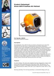
Gasmizer Manual - Submarine Manufacturing and Products Ltd
Gasmizer Manual - Submarine Manufacturing and Products Ltd
Gasmizer Manual - Submarine Manufacturing and Products Ltd

Create successful ePaper yourself
Turn your PDF publications into a flip-book with our unique Google optimized e-Paper software.
March 09<br />
If the adjusting Screw (19) or Spring Cap (13) should need lubrication or replacement,<br />
the following procedure may be followed.<br />
1. Refer to O-Ring, seat <strong>and</strong> seal replacement, Dis-assembly para (b) (1) to (4).<br />
2. Remove screw (23) <strong>and</strong> the Adjusting screw Assembly <strong>and</strong> Thrust Bearing 915 will<br />
drop out.<br />
3. Lubricate using Chrisolube MCG 111 compound <strong>and</strong> re-assemble, paying attention<br />
to para (4) of the Assembly procedure in Servicing, O-ring, Seat <strong>and</strong> Seal<br />
Replacement.<br />
6.6.9 Sensor Dismantling <strong>and</strong> Re-assembly<br />
Dis-assembly<br />
1. Unscrew Spring Pad (6) from sensor 91) using a 1/2" open end wrench or a vise jaw<br />
to hold Spring Pad (6) <strong>and</strong> a 1/2" wide screwdriver (or a 1” open end wrench depending<br />
upon sensor) to loosen Sensor (1) <strong>and</strong> Sensor back up are then merely pushed<br />
apart.<br />
2. To expose Vent valve (7) <strong>and</strong> Spring (2) it is necessary to forcefully remove Vent<br />
Valve Seat (8) which quite possibly will cause permanent damage to this seat <strong>and</strong><br />
require replacement. The removal can be made with any sharp pointed instrument.<br />
Assembly<br />
1. If sensor O-ring (4) requires lubricant, apply Christolube MCG 111 or other suitable<br />
non-hydrocarbon grease.<br />
2. Re-assemble O-ring (4), Back up Ring (5), Sensor Back –up (3) <strong>and</strong> sensor.<br />
3. Hold both members in a vertical position <strong>and</strong> carefully thread Spring Pad (6) onto<br />
Sensor (1) <strong>and</strong> tighten to a maximum torque loading of 75-90 ft. lbs.<br />
6.6.10 Main valve Dis-assembly <strong>and</strong> Re-assembly<br />
Dis-assembly<br />
1. Clamp valve Body (26) in smooth jawed vice or hold with pliers. Claming is done on<br />
shoulders that hold O-ring (32) <strong>and</strong> Back-up Ring (31). If pliers are used, a protecting<br />
cover should be placed over the jaws. Remove Seat Retainer (30) with 1/2" wrench<br />
(left-h<strong>and</strong> thread).<br />
2. To remove Spring (36) <strong>and</strong> main Valve (35), unscrew Filter Assembly (37) from<br />
body (34). This is a finger tight engagement.<br />
3. Remove Seat (33) with a sharp pointed tool.<br />
Re-assembly<br />
1. Install new seat (33) in Retainer (30) with chamfer of Seat toward Valve (35).<br />
2. Fit seat Retainer (30) <strong>and</strong> torque tighten to a recommended 100-110 in. lbs.<br />
3. Refit Valve Spring (36) <strong>and</strong> Filter Assembly (37).<br />
Trouble Shooting<br />
OM002 Rev 5 Page 66 of 168 Chap 6