Gasmizer Manual - Submarine Manufacturing and Products Ltd
Gasmizer Manual - Submarine Manufacturing and Products Ltd
Gasmizer Manual - Submarine Manufacturing and Products Ltd

You also want an ePaper? Increase the reach of your titles
YUMPU automatically turns print PDFs into web optimized ePapers that Google loves.
March 09<br />
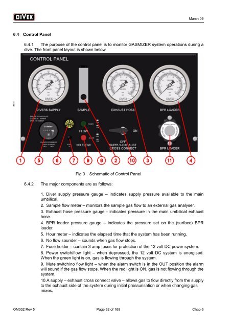
6.4 Control Panel<br />
6.4.1 The purpose of the control panel is to monitor GASMIZER system operations during a<br />
dive. The front panel layout is shown below.<br />
Fig 3<br />
Schematic of Control Panel<br />
6.4.2 The major components are as follows:<br />
1. Diver supply pressure gauge – indicates supply pressure available to the main<br />
umbilical.<br />
2. Sample flow meter – monitors the sample gas flow to an external gas analyser.<br />
3. Exhaust hose pressure gauge - indicates pressure in the main umbilical exhaust<br />
hose.<br />
4. BPR loader pressure gauge – indicates the pressure set on the (surface) BPR<br />
loader.<br />
5. Hour meter – indicates the elapsed time that the system has been running.<br />
6. No flow sounder – sounds when gas flow stops.<br />
7. Fuse holder – contain 3 amp fuses for protection of the 12 volt DC power system.<br />
8. Power switch/flow light – when depressed, the 12 volt DC system is energised.<br />
When the green light is on, gas is flowing through the system.<br />
9. Mute switch/no flow light – when the alarm switch is in the OUT position the alarm<br />
will sound if the gas flow stops. When the red light is ON, gas is not flowing through the<br />
system.<br />
10.A supply – exhaust cross connect valve – allows gas to flow directly from the supply<br />
to the exhaust side of the system during initial pressurisation or when changing gas<br />
mixes.<br />
OM002 Rev 5 Page 62 of 168 Chap 6