HGQ & HGS Energy Meter - Brunata
HGQ & HGS Energy Meter - Brunata
HGQ & HGS Energy Meter - Brunata

Create successful ePaper yourself
Turn your PDF publications into a flip-book with our unique Google optimized e-Paper software.
Installation<br />
Preparation for installation<br />
Please note that the installation must be done in such a way that it meets the requirements<br />
for internal fitting, distances that have to be respected, etc. Straight pipe sections<br />
before or after the meter are not required.<br />
NB! It is recommended that stop valves are fitted before and after the meter to<br />
make it easier to remove and re-install the meter if service and verification are<br />
required. To ensure that there are no foreign bodies in the pipe section, it is recommended<br />
that the pipes are flushed through before the meter is installed. A<br />
adapter pipe can be used for this purpose. After installation, the valves should be<br />
opened in the order which provides correct flow through the meter.<br />
The HG-meter has been approved for installation in industrial areas, but it is recommended<br />
that installation close to components that may cause strong electro-magnetic<br />
interference is avoided.<br />
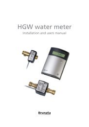
Installation of the flow sensor<br />
The flowsensor is installed with the arrow in the flow direction. The flow sensor can<br />
be installed in any direction (vertically, horizontally etc), only the flow sensor must always<br />
be filled with water when running. Do not insulate the housing of the flow sensor.<br />
The meter’s type label will indicate whether the flow sensor should be fitted on the return<br />
pipe (low temperature) or the supply pipe (high temperature). Please note that if the meter<br />
is used in a cooling system, the supply pipe is low temperature.<br />
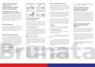
Fitting and connection of display unit<br />
The display unit must be fitted on a flat surface with 3 screws. All connections to the<br />
meter must be fitted before mains voltage is connected.<br />
The connection cable from the flow sensor is fitted with a 4-pole plug [1] in fig.1, which<br />
is connected with its opposite [1] in fig.1. Turn the plug the right way round. The cable<br />
is squeezed into the strain relief and the rubber cable guide on the cable is pushed into<br />
place in the box. The other cables that need to be connected are led through rubber<br />
membrane and bypass and connected with their respective terminals. Temperature sensors<br />
are connected with terminal [2] and [3], pulse inputs with terminal [9] and [10],<br />
and the remote read-ing with terminal [5] and [6]. A small screwdriver or the like can be<br />
used to perforate the rubber membrane.<br />
A power supply cable for 230 Volt (possibly 24 Volt) is led through the rubber membrane<br />
and connected with terminal [4] in fig.1, then the strain relief is tightened moderately.<br />
Earth connection is not required.