HGQ & HGS Energy Meter - Brunata
HGQ & HGS Energy Meter - Brunata
HGQ & HGS Energy Meter - Brunata

Create successful ePaper yourself
Turn your PDF publications into a flip-book with our unique Google optimized e-Paper software.
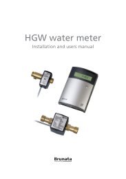
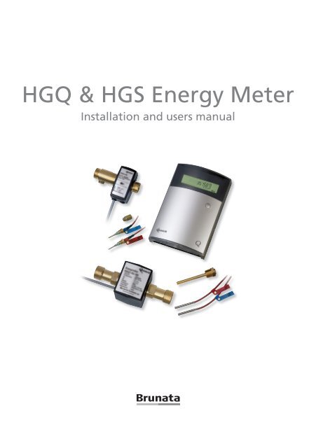
<strong>HGQ</strong> & <strong>HGS</strong> <strong>Energy</strong> <strong>Meter</strong><br />
Installation and users manual
Please read this before installation<br />
This manual is intended for skilled personal having a formal knowledge to meters.<br />
The <strong>Brunata</strong> <strong>HGQ</strong> / <strong>HGS</strong> energy meter must only be used and installed as described in<br />
the manual.<br />
The working data of the meter are shown on the label of the meter. For further information<br />
we refer to the data sheet.<br />
IMPORTANT: Seals and void labels must not be removed or damaged. This will infringe<br />
the warranty of the meter.<br />
The meter contains of following parts:<br />
1. Flow sensor<br />
2. Display unit<br />
3. Two paired temperature sensors<br />
- <strong>HGQ</strong>: Direct sensors with fittings<br />
- <strong>HGS</strong>: pocket sensors with pockets<br />
4. Installation and users manual<br />
When unpacking the meter, please check that all parts are enclosed. The serial numbers<br />
of the flow sensor, the electronic units, and the temperature sensors must be identical,<br />
since the parts are calibrated. The serial number is also programmed into the memory<br />
of the meter, the Service Menu.<br />
Versions and ordering code<br />
xx: <strong>Meter</strong>:<br />
Q1: 1,6 m 3 /h<br />
Q3: 3,0 m 3 /h<br />
S5: 5,0 m 3 /h<br />
S9: 9,0 m 3 /h<br />
S16: 16,0 m 3 /h<br />
y: Connection size:<br />
R0: G¾B x 110 mm<br />
R3: G1B x 130 mm<br />
R4: G1B x 190 mm<br />
R6: G1¼B x 260 mm<br />
z: Menu/display:<br />
182: Standardversion<br />
184: Standardversion<br />
with peak values<br />
185: Heat- / cooling meter<br />
188: Tariff meter<br />
HGxx-yy-18z/ABCDEF<br />
A: Power supply:<br />
1: 230 VAC<br />
2: 24 VAC<br />
B: Display backlight:<br />
B: With/-: Without<br />
C: External meters:<br />
0, 1 or 2<br />
D: Communication module:<br />
M-Bus / LonWorks / RS232<br />
/ - ingen<br />
E: No. of accounting periods:<br />
0 / 6 / 12 / 24<br />
F: Programmered for Glycol<br />
(% in service menu)
Installation<br />
Preparation for installation<br />
Please note that the installation must be done in such a way that it meets the requirements<br />
for internal fitting, distances that have to be respected, etc. Straight pipe sections<br />
before or after the meter are not required.<br />
NB! It is recommended that stop valves are fitted before and after the meter to<br />
make it easier to remove and re-install the meter if service and verification are<br />
required. To ensure that there are no foreign bodies in the pipe section, it is recommended<br />
that the pipes are flushed through before the meter is installed. A<br />
adapter pipe can be used for this purpose. After installation, the valves should be<br />
opened in the order which provides correct flow through the meter.<br />
The HG-meter has been approved for installation in industrial areas, but it is recommended<br />
that installation close to components that may cause strong electro-magnetic<br />
interference is avoided.<br />
Installation of the flow sensor<br />
The flowsensor is installed with the arrow in the flow direction. The flow sensor can<br />
be installed in any direction (vertically, horizontally etc), only the flow sensor must always<br />
be filled with water when running. Do not insulate the housing of the flow sensor.<br />
The meter’s type label will indicate whether the flow sensor should be fitted on the return<br />
pipe (low temperature) or the supply pipe (high temperature). Please note that if the meter<br />
is used in a cooling system, the supply pipe is low temperature.<br />
Fitting and connection of display unit<br />
The display unit must be fitted on a flat surface with 3 screws. All connections to the<br />
meter must be fitted before mains voltage is connected.<br />
The connection cable from the flow sensor is fitted with a 4-pole plug [1] in fig.1, which<br />
is connected with its opposite [1] in fig.1. Turn the plug the right way round. The cable<br />
is squeezed into the strain relief and the rubber cable guide on the cable is pushed into<br />
place in the box. The other cables that need to be connected are led through rubber<br />
membrane and bypass and connected with their respective terminals. Temperature sensors<br />
are connected with terminal [2] and [3], pulse inputs with terminal [9] and [10],<br />
and the remote read-ing with terminal [5] and [6]. A small screwdriver or the like can be<br />
used to perforate the rubber membrane.<br />
A power supply cable for 230 Volt (possibly 24 Volt) is led through the rubber membrane<br />
and connected with terminal [4] in fig.1, then the strain relief is tightened moderately.<br />
Earth connection is not required.
Connecting terminals<br />
Ledningsförbindelser och anslutningsklämmer<br />
Displayenhet Display unit<br />
1<br />
13<br />
12<br />
11<br />
10<br />
9<br />
2 3 4<br />
5 6 7 8<br />
NR. MÄRKNING ANSLUTNING<br />
Fig. 1 Connecting terminals Display Unit<br />
1 FLÖDESSENSOR .. 4-polig, skärmad stickkontakt till flödessensorkabel<br />
2 HIGH No. TEMP. Indication ........... Temperatursensor, Installation<br />
PULSVÄRDEN:<br />
varma rör (röd)<br />
3 LOW 1TEMP............. FLOWSENSOR Temperatursensor, 4-legged kalla shielded rör (blå) plug for flow sensor cable Mätarens volymp<br />
4 230 VAC.................. Strömspänning (Kan vara 24 VAC)<br />
är beroende av<br />
5 A1 B1. 2 ................... HIGH TEMP. 1. Anslutning Temp. av datakommunikation, sensor, high M-Bus, Lon eller RS232 mätarens storlek.<br />
6 A2 B2. 3 ................... LOW TEMP. 2. Anslutning Temp. av datakommunikation, sensor, low M-Bus, Lon eller RS232 Framgår av<br />
7 - VOL. +................... Öppen kollektor pulsutgång, volym<br />
typmärket.<br />
8 - ENERGI 4 230 +. ............ V AC. Öppen kollektor Power pulsutgång, (24VAC is energi possible)<br />
Energipuls har<br />
9 - AUX2 +. ................ Extern pulsingång från t ex elmätare<br />
5 A1 B1. 1<br />
10 - AUX1 +. ................ Extern pulsingång st Installation of datacommunication, MBus, Lon or RS232 samma värde som<br />
från t ex kallvattenmätare<br />
sista siffran i<br />
11 Kontakter 6 1 A2 & 2 B2. ....... Kontakter för 2 nd tillkoppling Installation av of intern datacommunication, +5 V till AUX- ingångarna MBus, Lon or RS232<br />
displayen.<br />
12 0 V +5 V. ................ Genemsam noll och +5 V DC utgång<br />
Har t ex MWh-display<br />
13 M52. ........................<br />
7 - VOL. +.<br />
Stickkontakt<br />
Open<br />
för datakommunikationskort,<br />
collector pulse out, volume<br />
M-Bus, Lon eller RS232<br />
siffror efter kommat, ä<br />
8 - ENERGI +. Open collector pulse out, energy<br />
9 - AUX2 +. External incoming pulse from f.inst. electricity meter<br />
Pulsutgångar 10 - för AUX1 volym +. och energi External incoming pulse from f.inst. cold water meter<br />
Pulsutgångens optokopplare strömförsörjs via belastningsmotstånd R, som dimensioneras enl. tabell<br />
11 Kontakter 1 & 2 Switches for connection of internal +5V to AUX terminals<br />
12 0 V +5 V. Common zero and +5V DC exit<br />
Inställning av extern<br />
+Vmax<br />
V<br />
1.5V<br />
28 V<br />
Motstånd R<br />
strömförsörjning 13 M52. R Connector for Imaxdata 20 communication mA module, MBus, Lon or RS232<br />
5mA<br />
(från mätare: 5 VDC)<br />
Von max 1,5 V<br />
+V R för I=5 mA<br />
ton=toff=140 ms är standardinställning<br />
Pulsperiod T= ton + toff = 280 ms.<br />
5 Values 700 of pulse<br />
+Voff<br />
10 The pulse 1,7 k value depends on size of the meter. Please consult the type sign.<br />
15 <strong>Energy</strong> 2,7 pulse k has the same value as the last digit in display.<br />
20 3,7 k<br />
Von toff ton<br />
F.inst. MWh-display shows 3 digits after comma, the value is 1 kWh/pulse<br />
24<br />
GND (0V)<br />
4,5 k<br />
Fig. 2 Anslutningsexempel för<br />
Pulsperioder från 40 till 1560 ms kan förekomma<br />
volympulsutgång med intern 5 V<br />
28 5,3 k<br />
försörjning<br />
<br />
+
Specification of Output Pulses:<br />
Pulse output for volume and energy<br />
The open collector pulse out is power supplied with load resistance R, whic<br />
The open collector pulse out is power supplied with load resistance R, which is dimensioned<br />
according to table<br />
table below.<br />
below.<br />
Setting of external <br />
voltage supply <br />
(from meter: 5 VDC) <br />
+ V −1.5V<br />
R =<br />
5mA<br />
+V R for I=5 mA <br />
5 700 Ω Ω<br />
<br />
10 1,7 k Ω Ω <br />
15 2,7 k Ω Ω <br />
<br />
20 3,7 k Ω Ω<br />
Ω<br />
24 4,5 k Ω<br />
pplied with load resistance R, which is Ω dimensioned according to<br />
28 5,3 k Ω<br />
<br />
<br />
<br />
<br />
<br />
<br />
<br />
<br />
<br />
<br />
<br />
<br />
<br />
1.5V<br />
mA<br />
<br />
<br />
<br />
<br />
<br />
<br />
<br />
Insertion og communication module<br />
A communication module RS262, M-Bus or LON is plugged into the display<br />
nected to the terminals A1+B1 and A2+B2, [5] and [6] in fig 2.<br />
+<br />
Connection of external meters with pulse outlet<br />
NB only valid for meters, which has been programmed for connection<br />
The meter accepts active as well as passive signal source. The most comm<br />
<br />
which are connected to the terminals AUX 1 or AUX 2 and the switch in pos<br />
Fig. 2 Example of connection for volume pulse out with internal 5V<br />
fig. 6. <br />
<br />
Insertion of<br />
Connection<br />
communication<br />
of meters<br />
module<br />
with active signal source is done as illustrated in pictu<br />
position OFF.<br />
A communication module RS262, M-Bus or LON is plugged into the display unit, and<br />
le the signal cable Each is con-nected of the 2 input to the AUX1 terminals and A1+B1 AUX2 and can A2+B2, be set [5] separately. and [6] in fig Please 1. note th<br />
s or LON is plugged into the display unit, and the signal cable is con-<br />
2, [5] and [6] in fig 2.<br />
<br />
Connection of external meters with pulse outlet<br />
(only valid for meters, which has been programmed for connection of external meters)<br />
<br />
h pulse outlet<br />
een programmed for connection of external meters.<br />
sive signal position source. ON as The shown most in common picture B, fig. is passive 3. signal source,<br />
X 1 or AUX 2 and the switch in position ON as shown in picture B,<br />
The meter accepts active as well as passive signal source. The most common is passive<br />
signal source, which are connected to the terminals AUX 1 or AUX 2 and the switch in<br />
Connection of meters with active signal source is done as illustrated in picture B, fig. 6<br />
with the switch in position OFF.<br />
Each of the 2 input AUX1 and AUX2 can be set separately. Please note the polarity,<br />
source is see done fig. as 3. illustrated in picture B, fig. 6 with the switch in<br />
be set separately. Please note the polarity, see fig. 6.
Connection of meters with active signal source is done as illustrated in picture B, fig. 6 with the switch in<br />
position OFF.<br />
Each of the 2 input AUX1 and AUX2 can be set separately. Please note the polarity, see fig. 6.<br />
<br />
+V on<br />
<br />
+ -<br />
<br />
AUX1 (Flödesmätare) AUX2<br />
Minus<br />
<br />
AUX1 (Flödesmätare) AUX2<br />
A. Aktiv signalkälla B. Passiv signalkälla<br />
<br />
Kontakter 1 & 2: OFF<br />
Kontakter 1 & 2: ON<br />
Galvaniskt A. Active åtskilt signal source B. Ej Passive galvaniskt signal åtskilt source<br />
Switch 1 & 2: OFF<br />
Switch 1 & 2: ON<br />
Galvanic separated NOT galvanic separated<br />
<br />
V off t on t off<br />
GND (0V)<br />
<br />
<br />
<br />
Input-specifikation<br />
<br />
Von<br />
V<br />
>2,5 V<br />
on<br />
>2,5 V<br />
Voff 50 ms<br />
Fig. 3 Anslutning av externa mätare<br />
<br />
<br />
Sealing<br />
<br />
Vesterlundvej 14 DK-2730 Herlev Denmark Tel:+45 7777 7000 Fax: +45 7777 7001<br />
E-mail: brunata@brunata.com Internet: www.brunata.com<br />
<br />
Fig. 3 Connection of external meters<br />
The flow electronic unit is from the factory sealed through the transparent lid and<br />
the screw allowing access to the terminals. After mounting and connecting the unit the<br />
black lid is screwed on and the unit can be sealed using sealing wire and a seal.<br />
The display unit is sealed electronically when delivered. The box is closed and sealed<br />
with <strong>Brunata</strong> special seal made of plastic, which is pushed into the narrow hole on the<br />
bottom of the box. The seal can be removed with a screwdriver. The broken piece of<br />
the seal is to be pushed into the box with the screwdriver and hereafter the box can be<br />
opened. Alternatively the box can be closed with the enclosed screw and sealed with<br />
thread through the hole next to the screw for the lid.<br />
The temperature sensors are sealed in their pockets using sealing wire and a seal.<br />
Head sensors are sealed through the hole in the locking screw.<br />
energi-IV-BV-DK4/08.05.2006 Copyright © <strong>Brunata</strong> a/s 2006 Sida 4<br />
<strong>Brunata</strong> a/s • Kapplöpningsg. 14 • Box 5066 • S-250 05 Helsingborg • Sverige • Tel:+46 (0)42-13 37 59<br />
Fax: +46 (0)42-18 74 65 • E-mail: brunata@brunata.se • Internet: www.brunata.se<br />
Putting the meter into operation<br />
Mains voltage is connected and the meters starts registration at once if you have flow.<br />
The meter does not sustain damage if there is no water in the system, but it may register<br />
a random flow in case the flow sensor is not completely filled with water.<br />
When the meter is connected and water is running through the flow sensor a square in<br />
the display is flashing concurrently with the water pulses.<br />
Attention: The meter’s counter cannot be zeroed after delivery.
PERATING MANUAL<br />
Operating manual<br />
he menu of the meter is structured in 3-4 menus, and you navigate from one display to another using the<br />
ush button on The the menu display of unit. the meter The following is structured illustration in 3-4 shows menus, the standard you menu navigate structure from one a <strong>Brunata</strong> display<br />
G energy meter to another using the push button on the display unit. The following illustration shows<br />
the standard menu structure on a <strong>Brunata</strong> HG energy meter<br />
<br />
3)<br />
<br />
<br />
<br />
<br />
<br />
<br />
<br />
<br />
2)<br />
<br />
<br />
<br />
<br />
<br />
<br />
<br />
<br />
<br />
<br />
<br />
<br />
<br />
<br />
<br />
<br />
2)<br />
<br />
<br />
<br />
<br />
<br />
<br />
<br />
<br />
<br />
<br />
1)<br />
1)<br />
<br />
<br />
<br />
<br />
Operating<br />
hours h<br />
<br />
<br />
<br />
<br />
<br />
<br />
<br />
<br />
<br />
<br />
<br />
<br />
<br />
1)<br />
1)<br />
4)<br />
<br />
<br />
<br />
<br />
<br />
<br />
<br />
<br />
<br />
<br />
<br />
<br />
<br />
<br />
<br />
<br />
<br />
2)<br />
2)<br />
<br />
<br />
<br />
<br />
<br />
<br />
<br />
<br />
<br />
<br />
<br />
<br />
<br />
<br />
<br />
<br />
<br />
<br />
2)<br />
4)<br />
<br />
<br />
<br />
<br />
<br />
<br />
<br />
<br />
<br />
HG-serial<br />
number<br />
<br />
<br />
<br />
<br />
Remarks<br />
Fig. 4 Display structure<br />
emarks<br />
1) Only 1) in meter Only in programmed meter programmed for pulse input for pulse from external input from meters external meters<br />
2) Only 2) in meter Only in type meter -188 type programmed -188 programmed with tariff functions with tariff functions<br />
3) File menu 3) File is menu included is included only if meter only is if programmed meter is programmed for storage of for data storage of data<br />
4) Only 4) in meter Only in programmed meter programmed for remote for reading remote reading
Operating the meter<br />
Introduction<br />
The meter is operated using the push button on the front<br />
of the electronic unit. Pressing once you step down in<br />
the actual menu you are in. By pressing the button in<br />
a few seconds, you can step from one menu to the<br />
next.<br />
Except for the User Menu the No. of the actual<br />
menu is shown in the display.<br />
Push<br />
button<br />
In case the meter is delivered with Storage Menu, the meter read itself and stores data<br />
as default on the 1st each month or at an optional selected date, see the order confirmation<br />
or consult the Service Menu. Until the first date occur the menu will be empty,<br />
displaying _ _._ _._ _._ _ Peak values are registered in the period from the 1st in actual<br />
month. Values are reset (zeroed) at each turn of the storing date e.g. for standard meters<br />
each month.<br />
In addition to registration of the highest return temperature (Peak tL) the concurrent<br />
flow temperature (Peak tH) is registered.<br />
With meters supplied with module for remote reading, the user himself in the User<br />
Menu can check the time where the meter has been read. The communication address<br />
of the meter appears in the Service Menu.<br />
Normal operation – User menu<br />
By pushing the button once there will be light in the display, and you will see the accumulated<br />
energy (MWh). When pushing once again the display will change to different<br />
pictures (see above). After the last display picture in the menu the display will show the<br />
accumulated energy (MWh) again.<br />
When the pushbutton has not been activated for approx. 1 minute the display will automatically<br />
return to accumulated volume (MWh) and the light will turn off.<br />
Advanced operation – all menus<br />
When holding down the button for a short while, the display will change from one<br />
menu to the next. The menu reached is indicated in the upper part of the display (except<br />
Menu 1). The order of the menus is therefore [none], 2, 3 and 4<br />
When you reach the needed menu, release the pushbutton and the menu is now activated.<br />
By pushing once the different display pictures in the chosen menu will show (as<br />
mentioned above).<br />
Display pictures containing peak values - f.inst. peak flow, peak power etc., will automatically<br />
alternate be-tween peak value and date/time of registration.
For meters delivered with tariff function the consumption is displayed in Tariff <strong>Energy</strong><br />
$ and Tariff volume $, according to the criteria’s selected. The selected criteria can be<br />
seen in the service menu.<br />
Stored data menu<br />
If the meter is programmed for storage of data, in menu 3 you find data stored for 24<br />
accounting periods, and you can step through the different periods by pressing the button<br />
quickly twice. The date and time when the data has been stored is shown as first<br />
display in each accounting period. The first period showed are the most recent. You<br />
can step through the information stored by pressing the button once.<br />
By pressing the button quickly twice you step to the next period, and after having<br />
reached the latest reading (register 24) you will again see the most recent readings.<br />
Information and error codes<br />
Should an error occur in the meter, the display will be flashing ”Error” followed by one<br />
of following error codes:<br />
1. Interruption of power supply. The information is logged in the error register, and not<br />
showed in the display.<br />
2. No registration of flow pulses within the last 24 hours, provided that the temperature<br />
difference has exceeded 20 °C.<br />
3. Error, temperature sensorT H<br />
, warmest pipe [-30 °C > T H<br />
> 200 °C].<br />
4. Error, temperature sensor T L<br />
, coldest pipe [-30 °C > T L<br />
> 200 °C].<br />
5. Low voltage in back-up battery [V Bat<br />
< V Treshold<br />
].<br />
6. Short circuit of magnet coil in the flowsensor [Coil current exceeds limit value for<br />
more than 8 sec].<br />
7. Error in the programming of the meter [RAM not initialised].<br />
8. The temperature sensors in flow pipe and return pipe are reversed [Negative temperature<br />
difference exceeds limit value for more than 10 sec].<br />
9. Wrong time/date in the meter (see Service Menu) – clock must be adjusted.<br />
In case of error the meter automatically will registers when (date and time) the error has<br />
occurred and also the accumulated error time.<br />
When two errors occur at the same time, both codes are shown. Example: Error code<br />
36 indicates problems with the temperature sensor in the warmest pipe and with the<br />
flow sensor.<br />
At code nos. 2, 3, 4, 6 and 8 the error message is shown in the display as long as the<br />
error occurs. The hours with error are registered in the register for Accumulated error
hours. If the power supply is terminated, the time without power is registered in the<br />
error hours register.<br />
At code 5, 7 and 9 the error message is shown in the display as long as the error occurs,<br />
but will not be reg-istered in the register for Accumulated error hours.<br />
By interruption of the power supply the display will be blank. When the power is reestablished<br />
the meter will immediately start registering again.<br />
By error code 5, low battery-supply, the meter will continue the normal registration as<br />
long as it is powered but the battery must be replaced as soon as possible.<br />
By error code 9, the meter has been without power supply, and battery-supply. The<br />
meter will continue the normal registration when power is restored, but the internal<br />
clock should be adjusted.<br />
At temperature difference below 0.1 K, the energy calculation will seize. The register<br />
“Accumulated flow sen-sor volume” will continue registering the flow.<br />
The meter’s operating hours counter starts registration as soon as the meter is connected<br />
to the mains.<br />
In case of questions, you are always welcome to contact your local <strong>Brunata</strong> service<br />
department, or send an e-mail to service@brunata.dk.<br />
10
Notes<br />
11
Notes<br />
<strong>Brunata</strong> a/s · Vesterlundvej 14 · DK-2730 Herlev · tel. +45 77 77 70 00<br />
fax +45 77 77 70 01 · www.brunata.com · brunata@brunata.com<br />
UK-QB 10.1483/04.09.2006<br />
12