Fused-Core⢠Particles for Very Fast HPLC Separations
Fused-Core⢠Particles for Very Fast HPLC Separations
Fused-Core⢠Particles for Very Fast HPLC Separations

Create successful ePaper yourself
Turn your PDF publications into a flip-book with our unique Google optimized e-Paper software.
GUIDE TO ULTRA-FAST <strong>HPLC</strong><br />
Quick Tips <strong>for</strong> Converting<br />
Conventional Reversed-Phase<br />
<strong>HPLC</strong> <strong>Separations</strong><br />
to Ultra-<strong>Fast</strong> <strong>Separations</strong>
GUIDE TO ULTRA-FAST <strong>HPLC</strong><br />
Quick Tips <strong>for</strong> Converting<br />
Conventional Reversed-Phase<br />
<strong>HPLC</strong> <strong>Separations</strong><br />
to Ultra-<strong>Fast</strong> <strong>Separations</strong><br />
T<br />
here has been enormous interest recently in so-called “ultra-fast”<br />
<strong>HPLC</strong> columns that can reduce run times by 70% or more. These<br />
ultra-fast columns are typically packed with particles considerably<br />
smaller than what is packed in conventional columns, giving them the<br />
advantage of equivalent separating power in much shorter length columns<br />
as well as the advantage that they maintain their separating power at higher<br />
mobile phase flow rates. The ability to use shorter columns and higher<br />
flow rates offers an opportunity to reduce analysis time and increase sample<br />
throughput significantly by substituting an ultra-fast column <strong>for</strong> a<br />
conventional column in an established method.<br />
To facilitate converting conventional reversed-phase separations to ultrafast<br />
separations, we have created this quick tips guide. It is intended to<br />
assist you in selecting an ultra-fast column and modifying conditions <strong>for</strong> a<br />
faster run time. In addition, this guide will help you estimate how the new<br />
ultra-fast conditions will affect run time, resolution, and back pressure.<br />
First, one qualification: An important chromatographic parameter that<br />
seems to be ignored in most discussions of ultra-fast <strong>HPLC</strong> is selectivity.<br />
Although selectivity is beyond the scope of this guide, you should be aware<br />
that converting from a conventional column to an ultra-fast column will<br />
sometimes be accompanied by a change in selectivity <strong>for</strong> one or more peak<br />
pairs in your chromatogram. This may be true if you continue to use the<br />
same bonded phase chemistry, such as C18, and even true if the ultra-fast<br />
column you choose is the same brand as the conventional column that it<br />
is replacing. However, in most cases the change in selectivity will be minor<br />
enough that the estimation models used in this guide will still be useful.<br />
— 1 —
Suggested Steps <strong>for</strong> Converting a<br />
Conventional Reversed-Phase Separation<br />
to an Ultra-<strong>Fast</strong> Separation<br />
1. Select the shortest ultra-fast column that can provide resolution<br />
equivalent to or better than the conventional column. See Figure A.<br />
2. Estimate the back pressure <strong>for</strong> the selected “ultra-fast” column. See<br />
Figure B. If the pressure exceeds the maximum acceptable pressure <strong>for</strong><br />
your system, select an alternate column with lower back pressure, most<br />
likely one packed with larger particles. You could elect to operate at a<br />
lower flow rate to keep the pressure acceptable, but this would also<br />
increase the run time, negating the purpose of converting to an ultrafast<br />
column.<br />
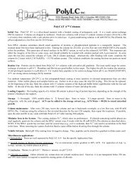
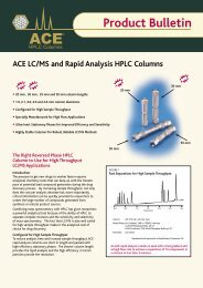
Figure A: Resolving Power as a Function of Particle Size and Column Length<br />
Instructions: This chart plots Resolving Power (the ability of a column to separate<br />
components in a mixture) versus column length <strong>for</strong> 7 different columns. Three of<br />
the columns are packed with conventional particles (5.0 μm, 3.5 μm, and 3.0 μm)<br />
and four are packed with ultra-fast particles (2.2 μm, 2.7 μm <strong>Fused</strong>-Core ® , 1.8 μm,<br />
and 1.7 μm). As column length increases, so does Resolving Power, but run time<br />
also increases. Notice that the ultra-fast columns provide greater Resolving Power<br />
in much shorter column lengths compared to the conventional columns. When<br />
converting a conventional separation to an ultra-fast separation, choose the shortest<br />
ultra-fast column that provides Resolving Power equal to or better than the<br />
conventional column it is replacing. This will allow you to minimize run time and<br />
maintain acceptable resolution.<br />
1.7 μm<br />
1.8 μm<br />
2.7 μm <strong>Fused</strong>-Core<br />
2.2 μm<br />
3.0 μm<br />
3.5 μm<br />
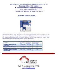
Figure B: Relative Back Pressure versus Particle Size<br />
Instructions: For the ultra-fast column configuration selected in Step 1 (length,<br />
particle size), estimate the expected back pressure on this column by multiplying the<br />
pressure observed on the conventional column by the ratio of the “Relative<br />
Pressure” of the ultra-fast column to the conventional column and then by the ratio<br />
of the column lengths.<br />
Note: This calculation assumes that the mobile phase velocity is the same <strong>for</strong> both the<br />
conventional column and the ultra-fast column.<br />
P 2 = P 1 x<br />
RP 2 L<br />
x 2<br />
RP 1<br />
L 1<br />
P 2 : Estimated back pressure of the<br />
ultra-fast column<br />
RP 2 : Relative back pressure of the<br />
ultra-fast column<br />
L 2 : Length of the ultra-fast column<br />
P 1 : Measured back pressure of<br />
conventional column<br />
RP 1 : Relative back pressure of the<br />
conventional column<br />
L 1 : Length of the conventional column<br />
RESOLVING POWER<br />
5.0 μm<br />
PARTICLE SIZE<br />
1.7 μm 8.7<br />
1.8 μm<br />
7.7<br />
2.2 μm<br />
5.2<br />
2.7 μm <strong>Fused</strong>-Core<br />
3.4<br />
3 μm<br />
2.8<br />
3.5 μm 2<br />
0<br />
50 100 150 200 250<br />
COLUMN LENGTH (mm)<br />
5 μm 1<br />
0 2 4 6 8 10<br />
RELATIVE BACK PRESSURE<br />
Example: A 100 mm ultra-fast column packed with 2.7 μm <strong>Fused</strong>-Core particles<br />
meets the criteria of providing equal or better Resolving Power compared to a<br />
250 mm column packed with conventional 5 μm particles. This ultra-fast column is<br />
an appropriate choice <strong>for</strong> replacing the 250 mm length conventional column in an<br />
ultra-fast method.<br />
Example: A 100 mm ultra-fast column packed with 1.8 μm particles will generate<br />
approximately 3 times the back pressure of a 250 mm conventional column packed<br />
with 5 μm particles.<br />
7.7 100 mm<br />
P ULTRA-FAST COLUMN<br />
= P 1<br />
x x = 3.08 x P<br />
1 250 mm<br />
CONVENTIONAL COLUMN<br />
— 2 —<br />
— 3 —
3. Confirm that the selectivity and resolution of the ultra-fast column is<br />
adequate. Since the selectivity of the ultra-fast column may be different<br />
from the selectivity of the conventional column (this may be true even<br />
if both the conventional column and the ultra-fast column are the same<br />
brand), run your separation with the ultra-fast column and calculate<br />
resolution. If the resolution does not meet the minimum required<br />
resolution, you may have to choose a longer column, or possibly even<br />
a different brand of ultra-fast column (with a different selectivity) to<br />
achieve acceptable resolution. If the resolution exceeds the required<br />
resolution, you may be able to use an even shorter ultra-fast column, or<br />
at least operate at a higher mobile phase flow rate to reduce the run time<br />
even further.<br />
4. Once a column has been selected that provides acceptable resolution<br />
and pressure, increase the flow rate to minimize the run time while<br />
maintaining acceptable resolution and pressure. Considerable time<br />
savings and greater sample throughput can be achieved by operating at<br />
higher flow rates with an ultra-fast column, as long as you don’t exceed<br />
your system’s maximum back pressure. See Figure C.<br />
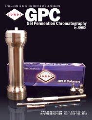
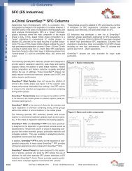
Figure C: Resolution versus Mobile Phase Flow Rate<br />
Instructions: : If the resolution on the selected ultra-fast column exceeds the<br />
minimum required resolution <strong>for</strong> the separation and does not exceed the pressure<br />
limit, you will be able to reduce analysis time further by increasing the flow rate.<br />
Since the optimum flow velocity (<strong>for</strong> maximum resolution) of an ultra-fast column is<br />
3 to 4 times faster than <strong>for</strong> a conventional column, you may actually be able to both<br />
reduce the run time and increase resolution by operating at a higher flow rate.<br />
This chart estimates change in resolution with changes in mobile phase velocity.<br />
Not only do ultra-fast columns have their optimum efficiency at higher mobile phase<br />
velocities, they also sacrifice less of their efficiency as mobile phase velocity is<br />
increased beyond their optimum.<br />
LOSS IN RESOLUTION<br />
20%<br />
15%<br />
10%<br />
5%<br />
Change in Resolution with Flow Rate<br />
5.0 μm<br />
2.7 μm <strong>Fused</strong>-Core<br />
3.5 μm<br />
3 μm<br />
2.2 μm<br />
1.8 μm<br />
1.7 μm<br />
0%<br />
0.1 0.2 0.3 0.4 0.5 0.6 0.7 0.8 0.9 1.0<br />
FLOW VELOCITY (cm/sec.)<br />
Example: An ultra-fast column packed with 2.7 μm <strong>Fused</strong>-Core particles can be<br />
operated at a relatively fast mobile phase velocity of 0.7 cm/sec and still retain over<br />
96% of its resolving power. A conventional column packed with 5 μm particles run<br />
at the same flow velocity would retain only about 82% of its resolving power.<br />
Converting Mobile Phase Velocity (cm/sec) to Column Flow Rate (ml/min)<br />
Mobile<br />
Phase<br />
Velocity<br />
Column ID (mm)<br />
1.0 2.1 3.0 4.6<br />
0.1 0.030 0.13 0.27 0.63<br />
0.2 0.059 0.26 0.53 1.3<br />
0.3 0.089 0.39 0.80 1.9<br />
0.4 0.12 0.52 1.1 2.5<br />
0.5 0.15 0.65 1.3 3.1<br />
Mobile<br />
Phase<br />
Velocity<br />
Column ID (mm)<br />
1.0 2.1 3.0 4.6<br />
0.6 0.18 0.79 1.6 3.8<br />
0.7 0.21 0.92 1.9 4.4<br />
0.8 0.24 1.0 2.1 5.0<br />
0.9 0.27 1.2 2.4 5.7<br />
1.0 0.30 1.3 2.7 6.3<br />
— 4 —<br />
— 5 —
5. If the separation uses gradient elution, you will need to adjust the<br />
gradient time (t G<br />
) to the volume of the ultra-fast column and <strong>for</strong> any<br />
changes in flow rate. See Figure D.<br />
6. Adjust the injection volume to the ultra-fast<br />
column’s volume. See Figure E.<br />
Figure D: Adjusting Gradient Time (t G<br />
) <strong>for</strong> Changes in Column Volume and<br />
Flow Rate<br />
Figure E: Adjust Sample Injection Volume <strong>for</strong><br />
Changes in Column Dimension<br />
t G2<br />
= t G1<br />
x<br />
V m2<br />
x F 1<br />
V m1<br />
F 2<br />
t G2 : Gradient time <strong>for</strong> the ultra-fast<br />
separation<br />
V m2 : Column volume of the ultra-fast<br />
column (see Table 1)<br />
F 2 : Flow rate <strong>for</strong> the ultra-fast<br />
separation<br />
t G1 : Gradient time <strong>for</strong> the<br />
conventional separation<br />
V m1 : Column volume of the<br />
conventional column (see Table 1)<br />
F 1 : Flow rate <strong>for</strong> the conventional<br />
separation<br />
S v2<br />
= S v1<br />
x V m2<br />
V m1<br />
S v2 : Injected sample volume <strong>for</strong> the ultra-fast column<br />
S v1 :<br />
Injected sample volume <strong>for</strong> the conventional<br />
column<br />
V m2 : Volume of the ultra-fast column (see Table 1)<br />
See Table on page 12 <strong>for</strong> estimates of column volumes <strong>for</strong> most commercially<br />
available column dimensions.<br />
Important Note: The system dwell volume (gradient mixing volume) can have a<br />
significant effect on the chromatography when using gradients because it adds an<br />
isocratic hold to the beginning of the gradient. The time of this “hold” is equal to the<br />
dwell volume divided by the flow rate. When the flow rate is changed, this isocratic<br />
hold will also change. This change in gradient hold will generally have more of an<br />
effect on early eluting peaks, but it will also affect all peaks in the chromatogram to<br />
some extent. To minimize the effect on your separation, keep the dwell volume as<br />
small as possible by using micro gradient mixers and keeping the tubing volume in<br />
the system to a minimum.<br />
V m1 : Volume of the conventional column (see Table 1)<br />
Example: A conventional method uses a sample<br />
injection volume of 20 μl on a column 4.6 x 150 mm.<br />
The sample volume that should be injected on to a<br />
4.6 x 50 mm ultra-fast column (2.7 μm <strong>Fused</strong>-Core) is:<br />
S v ULTRA-FAST<br />
= 20 μl x<br />
0.42 ml<br />
1.57 ml<br />
= 5 μl<br />
Example: A conventional method uses a column 4.6 x 150 mm (1.57 ml), a flow rate<br />
of 1.0 ml/min, and a gradient of 15% B to 35% B in 20.0 minutes. The gradient time<br />
<strong>for</strong> an ultra-fast method that uses a column 4.6 x 50 mm (2.7 μm <strong>Fused</strong>-Core,<br />
0.42 ml) and a flow rate of 2.0 ml/min is:<br />
t = 20 minutes x 0.42ml 1.0ml/min<br />
G ULTRA-FAST 1.57ml<br />
x 2.0ml/min<br />
= 2.7 min.<br />
— 6 —<br />
— 7 —
An Example of Converting a Conventional<br />
Separation to an Ultra-<strong>Fast</strong> Separation.<br />
Conventional <strong>HPLC</strong> Separation Conditions<br />
COLUMN: 4.6 x 250 mm, 5 μm<br />
FLOW RATE: 1.5 ml/min<br />
MOBILE PHASE: Isocratic<br />
RUN TIME: 10 minutes<br />
PRESSURE: 1,580 psi, 109 bar<br />
Maximum acceptable pressure = 4,000 psi, 275 bar<br />
RESOLUTION: 3.0<br />
SAMPLE INJECTION VOLUME: 20 μl<br />
Converting to Ultra-<strong>Fast</strong> Separation Conditions<br />
1. Select the shortest ultra-fast column that provides resolution<br />
equivalent to or better than the conventional column. (See Relative<br />
Resolution chart in Figure A.)<br />
A column 4.6 x 100 mm packed with 1.7 μm particles is selected<br />
<strong>for</strong> further investigation.<br />
2. Estimate back pressure. (See relative pressure table in Figure B.)<br />
8.7 100 mm<br />
P Ultra-<strong>Fast</strong> Column<br />
= 1,580 psi x x = 5,498 psi<br />
1 250 mm<br />
Since this ultra-fast column exceeds our maximum acceptable<br />
back pressure (4,000 psi), a different ultra-fast column is selected<br />
<strong>for</strong> investigation.<br />
The alternative ultra-fast column selected is a 4.6 x 100 mm packed<br />
with 2.7 μm <strong>Fused</strong>-Core particles (HALO <strong>HPLC</strong> column). The<br />
back pressure on this column is:<br />
3.4 100 mm<br />
P Ultra-<strong>Fast</strong> Column<br />
= 1,580 psi x x = 2,149 psi<br />
1 250 mm<br />
This ultra-fast column provides both acceptable resolution and<br />
acceptable back pressure <strong>for</strong> our method.<br />
3. Confirm that the selectivity and resolution of the ultra-fast column<br />
is adequate.<br />
For simplicity, we will assume that the selectivity of this ultra-fast<br />
column is almost identical to the selectivity of the conventional<br />
column and, there<strong>for</strong>e, the resolution is adequate.<br />
4. Optimize flow rate to minimize run time. (See Figure C to estimate<br />
changes in resolution with changes in flow rate.)<br />
We can further reduce run time by operating the ultra-fast<br />
column at a higher flow rate. We just have to make sure we stay<br />
within the requirements of minimum resolution and maximum<br />
pressure. The ultra-fast column we selected has low enough back<br />
pressure that we can operate at a flow rate of 2.5 ml/min and still<br />
stay within our defined limits of pressure and resolution.<br />
P at 2.5 ml/min<br />
= 2,149 psi x<br />
5. Adjust the gradient time.<br />
This is an isocratic separation, so no adjustment to gradient time<br />
is required.<br />
6. Adjust the injection volume. (See Figure D <strong>for</strong> calculations and table<br />
with estimated column volumes.)<br />
Sample volume =20 μl x<br />
Ultra-<strong>Fast</strong> Conditions<br />
2.5 ml/min<br />
1.5 ml/min<br />
0.84 ml<br />
2.62 ml<br />
= 3,582 psi<br />
= 6.4μl<br />
COLUMN: 4.6 x 100 mm, 2.7 μm <strong>Fused</strong>-Core (HALO®)<br />
FLOW RATE: 2.5 ml/min<br />
RUN TIME: 0.84 ml 1.5 ml/min<br />
10 min x x = 1.9 min*<br />
2.62 ml 2.5 ml/min<br />
RESOLUTION: 3.1<br />
PRESSURE: 3,582 psi<br />
SAMPLE INJECTION VOLUME: 6.4 μl<br />
* Run time <strong>for</strong> the ultra-fast separation can be estimated by multiplying the run time on the conventional column by the<br />
ratio of the volumes of ultra-fast column to the conventional column and then by the inverse ratio of the flow rates on<br />
the two columns. (See page 12)<br />
— 8 —<br />
— 9 —
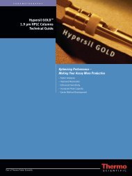
Conventional Separation<br />
COLUMN: 4.6 x 250 mm, 5 μm, C18<br />
FLOW RATE: 1.5 ml/min<br />
RESOLUTION: 3.0<br />
PRESSURE: 1,580 psi<br />
RUN TIME: 10 minutes<br />
SAMPLE INJECTION VOLUME: 20 μl<br />
Ultra-<strong>Fast</strong> Separation<br />
COLUMN: 4.6 x 100 mm, 2.7 μm <strong>Fused</strong>-Core, C18 (HALO® <strong>HPLC</strong> column)<br />
FLOW RATE: 2.5 ml/min<br />
RESOLUTION: 3.1<br />
PRESSURE: 3,582 psi<br />
RUN TIME: 1.9 minutes<br />
SAMPLE INJECTION VOLUME: 6.4 μl<br />
Rs = 3.0<br />
Rs = 3.1<br />
0 2 4 6 8 10 12<br />
TIME (minutes)<br />
0 0.5 1.0 1.5 2.0 2.5<br />
TIME (minutes)<br />
These are simulated chromatograms generated from theoretical data. Differences in selectivity between<br />
a conventional column and an ultra-fast column or changes in secondary retention interactions will yield<br />
different chromatographic results from what is predicted here.<br />
— 10 —<br />
— 11 —
Reference Tables and Equations <strong>for</strong><br />
Quick Estimates<br />
Table 1: Estimated volume, V m , <strong>for</strong> a variety of available column dimensions<br />
ID<br />
(mm)<br />
Length<br />
(mm)<br />
V m<br />
(ml)<br />
V m <strong>Fused</strong>-Core<br />
(ml)<br />
ID<br />
(mm)<br />
Length<br />
(mm)<br />
V m<br />
(ml)<br />
V m <strong>Fused</strong>-Core<br />
(ml)<br />
1.0 20 0.010 0.008<br />
1.0 30 0.015 0.012<br />
1.0 50 0.025 0.020<br />
1.0 75 0.037 0.030<br />
1.0 100 0.050 0.040<br />
1.0 150 0.074 0.059<br />
1.0 250 0.124 0.099<br />
2.1 20 0.044 0.035<br />
2.1 30 0.066 0.052<br />
2.1 50 0.109 0.087<br />
2.1 75 0.164 0.131<br />
2.1 100 0.218 0.175<br />
2.1 150 0.327 0.262<br />
2.1 250 0.546 0.436<br />
3.0 20 0.089 0.071<br />
3.0 30 0.134 0.107<br />
3.0 50 0.223 0.178<br />
3.0 75 0.334 0.267<br />
3.0 100 0.445 0.356<br />
3.0 150 0.668 0.534<br />
3.0 250 1.11 0.89<br />
4.6 20 0.209 0.168<br />
4.6 30 0.314 0.251<br />
4.6 50 0.524 0.419<br />
4.6 75 0.785 0.628<br />
4.6 100 1.05 0.84<br />
4.6 150 1.57 1.26<br />
4.6 250 2.62 2.09<br />
Note: Column volumes listed here are estimates only. However, most commercial columns can be expected<br />
to have volumes within about 5% of what is reported here. Columns packed with <strong>Fused</strong>-Core particles are an<br />
exception and, there<strong>for</strong>e, are listed separately.<br />
Table 2: Column plate number, N, <strong>for</strong> columns packed with different size/type particles<br />
Not like other<br />
ultra-fast<br />
<strong>HPLC</strong> columns.<br />
Particle<br />
N per cm of column length<br />
Particle<br />
N per cm of column length<br />
5 μm<br />
3.5 μm<br />
3 μm<br />
2.2 μm<br />
800<br />
1140<br />
1330<br />
1800<br />
2.7 μm <strong>Fused</strong>-Core<br />
1.8 μm<br />
1.7 μm<br />
2200<br />
2220<br />
2300<br />
Note: Estimates in this Table are <strong>for</strong> near ideal conditions. Column plate number is dependent on many factors<br />
including the solute, mobile phase viscosity and flow velocity and it is not unusual under “real-world” conditions<br />
<strong>for</strong> column plate numbers to be over 20% lower than what is reported here.<br />
Estimating changes in run time with changes in column volume and flow rate<br />
RT ultra-fast<br />
= RT conventional<br />
x<br />
V ultra-fast<br />
V conventional<br />
RT = Run Time<br />
V = Column Volume<br />
F = Flow rate (If column ID changes, mobile phase velocity should be used instead of flow rate.)<br />
Estimating changes in Resolution with changes in column plate number<br />
x<br />
F ultra-fast<br />
F conventional<br />
HALO <strong>HPLC</strong> columns made with <strong>Fused</strong>-Core ® particle technology<br />
are hyper-fast and super-rugged. Their low back pressure allows<br />
them to be used with conventional <strong>HPLC</strong> equipment as well as<br />
ultra-high pressure systems.<br />
Rs ultra-fast<br />
= Rs conventional<br />
x<br />
N ultra-fast<br />
N conventional<br />
Rs = Resolution<br />
N = Column plate number<br />
HALO columns can turn almost any <strong>HPLC</strong> into a<br />
high speed workhorse <strong>for</strong> your laboratory.<br />
— 12 — HALO and <strong>Fused</strong>-Core are registered trademarks of Advanced Materials Technology, Inc.
www.advanced-materials-tech.com<br />
LC489