Accessories - Portal - Kollmorgen Europe
Accessories - Portal - Kollmorgen Europe
Accessories - Portal - Kollmorgen Europe

You also want an ePaper? Increase the reach of your titles
YUMPU automatically turns print PDFs into web optimized ePapers that Google loves.
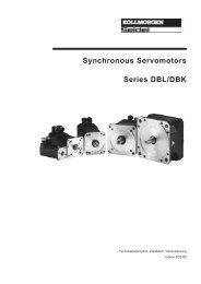
<strong>Accessories</strong><br />
for digital drive systems<br />
Manual<br />
Edition 07/2007<br />
Keep all manuals as a product component<br />
during the life span of the product.<br />
Pass all manuals to future users / owners<br />
of the product.<br />
File zubehoer_e.***
Previous editions<br />
Edition Comments<br />
04/07 First edition<br />
07/07 System S700 updated<br />
SERVOSTAR is a registered trademark of Danaher Motion<br />
Technical changes to improve the performance of the equipment may be made without notice !<br />
Printed in the Federal Republic of Germany<br />
All rights reserved. No part of this work may be reproduced in any form (by printing, photocopying, microfilm or any other<br />
method) or processed, copied or distributed by electronic means without the written permission of Danaher Motion.
Danaher Motion 07/2007 Contents<br />
Page<br />
1 General<br />
1.1 About this manual ....................................................................... 5<br />
1.2 Hints for the online edition (PDF format) ...................................................... 5<br />
1.3 Symbols used. .......................................................................... 5<br />
1.4 General safety instructions. ................................................................ 5<br />
2 Digital Drive Systems<br />
2.1 Drive System with S200 ................................................................... 6<br />
2.2 Drive System with S300 ................................................................... 7<br />
2.3 Drive System with S400 ................................................................... 8<br />
2.4 Drive System with S601...620 .............................................................. 9<br />
2.5 Drive System with S640/670 .............................................................. 10<br />
2.6 Drive System with S700 .................................................................. 11<br />
3 PC connection<br />
3.1 General .............................................................................. 13<br />
3.2 Order codes ........................................................................... 13<br />
3.3 PC connection serial RS232 .............................................................. 13<br />
3.4 PC connection serial USB ................................................................ 13<br />
3.5 Y-Adapter for S300, S600, S700 ........................................................... 14<br />
3.6 Firmware Upgrade ...................................................................... 14<br />
3.6.1 S200 ........................................................................... 14<br />
3.6.2 S300, S400, S600, S700 ............................................................ 14<br />
4 Cables<br />
4.1 Technical data for cables ................................................................. 15<br />
4.2 Voltage Supply, external regen resistor, DC bus link ............................................ 16<br />
4.3 Digital/analog Inputs/Outputs .............................................................. 16<br />
4.4 ROD/SSI, Stepper motor control, Master-Slave. ............................................... 17<br />
4.4.1 General ......................................................................... 17<br />
4.4.2 Preparing cables .................................................................. 18<br />
4.5 Configured motor cables ................................................................. 19<br />
4.5.1 General ......................................................................... 19<br />
4.5.2 Amplifier end ..................................................................... 19<br />
4.5.3 Order codes motor cables (with IP65 connectors) for S200. ................................. 20<br />
4.5.4 Order codes motor cables for S300 .................................................... 20<br />
4.5.5 Order codes motor cables for S400 .................................................... 20<br />
4.5.6 Order codes motor cables for S601...620 ............................................... 21<br />
4.5.7 Order codes motor cables for S700 .................................................... 21<br />
4.6 Configured Resolver cable. ............................................................... 22<br />
4.6.1 General ......................................................................... 22<br />
4.6.2 Oder codes Resolver cable for S300, S400, S600, S700 ................................... 22<br />
4.7 Configured SFD cable ................................................................... 22<br />
4.7.1 General ......................................................................... 22<br />
4.7.2 Order codes SFD cable (with IP65 connectors) for S200. ................................... 22<br />
4.8 Configured Encoder cable ................................................................ 23<br />
4.8.1 General ......................................................................... 23<br />
4.8.2 Order Codes ..................................................................... 23<br />
4.9 Configured ComCoder cable .............................................................. 23<br />
4.9.1 General ......................................................................... 23<br />
4.9.2 Order Codes ..................................................................... 23<br />
5 Shield clamps<br />
5.1 Safety instructions ...................................................................... 25<br />
5.2 Auxiliary terminals on the servo amplifier. .................................................... 25<br />
5.3 External shielding busbar. ................................................................ 26<br />
<strong>Accessories</strong> manual 3
Contents 07/2007 Danaher Motion<br />
Page<br />
6 Power supply units (PSU)<br />
6.1 Safety instructions ...................................................................... 27<br />
6.2 External PSU 24V DC / 5A. ............................................................... 27<br />
6.3 External PSU 24V DC / 20A. .............................................................. 28<br />
7 Mains chokes<br />
7.1 General .............................................................................. 29<br />
7.2 Safety instructions ...................................................................... 29<br />
7.3 Type assignment ....................................................................... 29<br />
7.4 Order codes ........................................................................... 29<br />
7.5 Manis choke 3L ........................................................................ 30<br />
8 Mains filters<br />
8.1 General .............................................................................. 31<br />
8.2 Safety instructions ...................................................................... 31<br />
8.3 Type assignment ....................................................................... 31<br />
8.4 Order codes ........................................................................... 31<br />
8.5 Mains filters 1EF06...3EF16. .............................................................. 32<br />
8.6 Mains filters S2-1EF-06/16. ............................................................... 33<br />
8.7 Mains filters 3EF42...130 ................................................................. 34<br />
9 Regen resistors<br />
9.1 General .............................................................................. 35<br />
9.2 Safety Instructions ...................................................................... 35<br />
9.3 Type assignment ....................................................................... 35<br />
9.4 Order codes ........................................................................... 35<br />
9.5 External regen resistor BAR-P ............................................................. 36<br />
9.6 External regen resistor BAR(U) ............................................................ 37<br />
9.7 External regen resistor BAS. .............................................................. 38<br />
10 Motor chokes<br />
10.1 General .............................................................................. 39<br />
10.2 Safety Instructions ...................................................................... 40<br />
10.3 Type assignment ....................................................................... 40<br />
10.4 Order codes ........................................................................... 40<br />
10.5 Motor choke 3YL20 ..................................................................... 41<br />
4 <strong>Accessories</strong> manual
Danaher Motion 07/2007 General<br />
1 General<br />
1.1 About this manual<br />
This manual describes accessories for Danaher Motion digital servo amplifiers. It contains essential<br />
technical data. The manual is only valid in conjunction with the product manuals for the servo amplifier<br />
and servo motor you are using in your application.<br />
You will find copies of the product manuals for Danaher Motion servo amplifiers and servo motors<br />
on the CD ROM included in the scope of supply and on our Internet site. The documents are available<br />
in Acrobat Reader format in multiple languages (system requirements: WINDOWS, Internet<br />
browser, Acrobat Reader).<br />
Servo amplifier product family names appear in abbreviated format:<br />
Servo amplifier Abbreviation Servo amplifier Abbreviation<br />
SERVOSTAR 200 S200 SERVOSTAR 601...620 S601...620<br />
SERVOSTAR 300 S300 SERVOSTAR 640/670 S640/670<br />
SERVOSTAR 400 S400 S700 S700<br />
1.2 Hints for the online edition (PDF format)<br />
Bookmark:<br />
Table of contents and index are active bookmarks.<br />
Table of contents and index in the text:<br />
The lines are active cross references. Click on the desired line and the appropriate page is indicated.<br />
Page/chapter numbers in the text:<br />
Page/chapter numbers with cross references are active. Click at the page/chapter number to reach<br />
the indicated target.<br />
1.3 Symbols used<br />
Danger to personnel from<br />
electricity and its effects effects<br />
Danger to maschinery, general<br />
warning<br />
Important notes<br />
p. see page special emphasis<br />
1.4 General safety instructions<br />
<br />
<br />
<br />
<br />
This manual is only valid in conjunction with the product manuals for the servo amplifier<br />
and servo motor you are using in your application.<br />
You must read the product manuals for the servo amplifier and servo motor you are<br />
using in your application and observe the safety instructions they contain before commencing<br />
mounting/installation work.<br />
Improper or incorrect cable assembly, mounting or wiring can result in damage to property<br />
and equipment or personal injury. The following requirements of specialist personnel<br />
apply:<br />
Transport:<br />
only by personnel with knowledge of handling<br />
electrostatically sensitive components.<br />
Unpacking: only by electrically qualified personnel.<br />
Cable assembly: only by electrically qualified personnel<br />
Installation: only by electrically qualified personnel.<br />
Commissioning: only by qualified personnel with extensive knowledge of<br />
electrical engineering / drive technology.<br />
Observe the specific safety instructions for each product group.<br />
<strong>Accessories</strong> manual 5
Digital Drive Systems 07/2007 Danaher Motion<br />
2 Digital Drive Systems<br />
The systems shown are simply a possible scenario for setting up a digital drive system with relevant<br />
servo amplifier components.<br />
2.1 Drive System with S200<br />
Control / PLC<br />
PC p.13<br />
I/O p.16<br />
SFD-Feedback p.22<br />
Motor-Power<br />
p.19<br />
Motor choke<br />
(optional) p.39<br />
Regen Resistor p.30<br />
Mains Filter p.31<br />
Cables drawn bold are shielded. Electrical ground is<br />
drawn with dash-dotted lines. Optional devices are<br />
connected with dashed lines to the servo amplifier.<br />
6 <strong>Accessories</strong> manual
Danaher Motion 07/2007 Digital Drive Systems<br />
2.2 Drive System with S300<br />
PC p.13<br />
Control / PLC<br />
I/O p.16<br />
Motor-Feedback<br />
p.22<br />
24V-PSU<br />
p.27<br />
Motor-Power<br />
p.19<br />
Regen Resistor<br />
(optional) p.37<br />
Motor choke<br />
(optional) p.39<br />
Cables drawn bold are shielded. Electrical ground is<br />
drawn with dash-dotted lines. Optional devices are<br />
connected with dashed lines to the servo amplifier.<br />
<strong>Accessories</strong> manual 7
Digital Drive Systems 07/2007 Danaher Motion<br />
2.3 Drive System with S400<br />
Control / PLC<br />
I/O p.16<br />
Regen Resistor<br />
(optional) p.37<br />
PC p.13<br />
24V-PSU<br />
p.27<br />
Motor-Feedback<br />
p.22<br />
Motor-Power<br />
p.19<br />
Cables drawn bold are shielded. Electrical ground is<br />
drawn with dash-dotted lines. Optional devices are<br />
connected with dashed lines to the servo amplifier.<br />
8 <strong>Accessories</strong> manual
Danaher Motion 07/2007 Digital Drive Systems<br />
2.4 Drive System with S601...620<br />
PC p.13<br />
Motor-Feedback<br />
p.22<br />
Control / PLC<br />
I/O p.16<br />
24V-PSU<br />
p.27<br />
Regen Resistor<br />
(optional) p.37<br />
Motor choke (optional)<br />
p.39<br />
Motor-Power<br />
p.19<br />
Cables drawn bold are shielded. Electrical ground is<br />
drawn with dash-dotted lines. Optional devices are<br />
connected with dashed lines to the servo amplifier.<br />
<strong>Accessories</strong> manual 9
Digital Drive Systems 07/2007 Danaher Motion<br />
2.5 Drive System with S640/670<br />
PC p.13<br />
Control / PLC<br />
I/O p.16<br />
24V-PSUl<br />
p.27<br />
Mains filter p.34<br />
Mains choke<br />
p.30<br />
Regen Resistor<br />
p.38<br />
Motor-Power<br />
p.19<br />
Motor-Feedback<br />
p.22<br />
Cables drawn bold are shielded. Electrical ground is<br />
drawn with dash-dotted lines.<br />
10 <strong>Accessories</strong> manual
Danaher Motion 07/2007 Digital Drive Systems<br />
2.6 Drive System with S700<br />
PC p.13<br />
Control / PLC<br />
I/O p.16<br />
Motor-Feedback<br />
p.22<br />
24V-PSU<br />
p.27<br />
Motor-Power<br />
p.19<br />
Regen Resistor<br />
optional p.37<br />
Motor choke<br />
(optional) p.39<br />
Cables drawn bold are shielded. Electrical ground is<br />
drawn with dash-dotted lines. Optional devices are<br />
connected with dashed lines to the servo amplifier.<br />
<strong>Accessories</strong> manual 11
Digital Drive Systems 07/2007 Danaher Motion<br />
This page has been deliberately left blank.<br />
12 <strong>Accessories</strong> manual
Danaher Motion 07/2007 PC connection<br />
3 PC connection<br />
3.1 General<br />
3.2 Order codes<br />
Danaher Motion digital servo amplifiers are equipped with a serial RS232 interface to facilitate communication<br />
with a standard personal computer (PC). Various types of interface can be used on the<br />
PC. Appropriate cables and in some cases specific accessories will be required to establish the<br />
connection between servo amplifier and PC.<br />
Article<br />
Cable PC-S200 1.8m, 9poles<br />
Cable PC-S300/S400/S600/S700 3m, 9poles<br />
Adapter 9-25 poles<br />
Setup Kit S200 USB<br />
Setup Kit S300/S400/S600/S700 USB<br />
Y-Programming-Adapter 1 Achse<br />
Y-Adapter -SR6Y- 4 axes<br />
Y-Adapter -SR6Y6- 6 axes<br />
Order Code<br />
P7S2-232-9D<br />
DE-90067<br />
DE-90105<br />
DE-107665<br />
DE-107666<br />
DE-108211<br />
DE-90060<br />
DE-92042<br />
3.3 PC connection serial RS232<br />
For the purpose of parameterisation and for firmware upgrades, the servo amplifiers can be connected<br />
to the serial RS232 interface on a PC. The connecting cable must be shielded. The braided<br />
shield on the RS232 connecting cable is conductively connected to the front panel of the servo<br />
amplifier via the connector housing on the Sub-D male connector.<br />
PC cable for S200<br />
PC cable for S300, S400, S600, S700<br />
3.4 PC connection serial USB<br />
An interface converter is required to use the USB interface on a PC. Our "USB" setup kits contain a<br />
USB serial converter and a serial PC cable suitable for the amplifier type.<br />
Setup Kit S200 USB<br />
Setup Kit S300, S400, S600, S700 USB<br />
<strong>Accessories</strong> manual 13
PC connection 07/2007 Danaher Motion<br />
3.5 Y-Adapter for S300, S600, S700<br />
The signals for the serial link to the PC and the CAN interface are routed via the same connector on<br />
the servo amplifier (X6). Our Y adapters can be used for simultaneous access to both interfaces. In<br />
this case, the interface signals are routed via separate connectors.<br />
Y programming adapter for 1 Axis<br />
The multi-axis Y adapters support the simultaneous<br />
setup (multi-link) of a number of servo amplifiers<br />
in a single setup session (not on the S300<br />
or S700):<br />
Y adapter for 4 axes<br />
Y adapter for 6 axes<br />
3.6 Firmware Upgrade<br />
3.6.1 S200<br />
On S200 servo amplifiers, an EEPROM has to be replaced. Please contact our customer service<br />
department for more information.<br />
3.6.2 S300, S400, S600, S700<br />
On these servo amplifiers, the firmware can be updated easily via the serial interface or the CAN<br />
bus.<br />
Hardware requirements<br />
The firmware stored in the servo amplifier is usually updated via the same serial link (RS232 or<br />
USB) used for setup. Additional hardware is needed to update the firmware via the CAN interface.<br />
Please contact our customer service department for more information.<br />
Software requirements<br />
You will need to download the "DriveDownloadUtility_..." utility from ourInternet site. Source files for<br />
upgrades can also be downloaded from our Internet site.<br />
14 <strong>Accessories</strong> manual
Danaher Motion 07/2007 Cables<br />
4 Cables<br />
4.1 Technical data for cables<br />
The following table lists the technical data for all cables we are able to supply. Further information<br />
on the chemical, mechanical and electrical characteristics of the cables can be obtained from our<br />
customer support.<br />
Insulation material<br />
Sheathing PUR (polyurethane, code 11Y)<br />
Core insulation PETP (polyesteraphthalate, code 12Y)<br />
Capacitance<br />
Motor cable<br />
RES/encoder cable<br />
less than 150 pF/m<br />
less than 120 pF/m<br />
Technical data<br />
— The brackets in the core definition indicate the shielding<br />
— All cables are suitable for use as trailing cables<br />
— The technical data refer to use as moveable cables<br />
— Operating life : 10 million bending cycles<br />
— All cables are UL recognized<br />
Cores<br />
[mm²]<br />
Operating<br />
Temperature Range<br />
[°C]<br />
Outside Diameter*<br />
[mm]<br />
min. Bending<br />
Radius*<br />
[mm]<br />
(4x1,0) -30 / +80 8,9 100<br />
(4x1,5) -30 / +80 9,9 105<br />
(4x2,5) -30 / +80 12,1 125<br />
(4x4) 0 / +80 13,2 140<br />
(4x10) -30 / +80 18,0 210<br />
(4x16) -30 / +80 22,7 260<br />
(4x25) -30 / +80 25,8 310<br />
(4x1,0+(2x0,75)) -30 / +80 12,2 105<br />
(4x1,5+(2x0,75)) -30 / +80 12,4 120<br />
(4x2,5+(2x1,0)) -30 / +80 14,2 145<br />
(4x4,0+(2x1,0)) 0 / +80 14,4 150<br />
(4x(2x0,25)) -30 / +80 8,0 70<br />
(7x(2x0,25)) -30 / +80 9,3 90<br />
(8x(2x0,25)) -30 / +80 10,6 100<br />
*Tolerance +/- 5%<br />
<strong>Accessories</strong> manual 15
Cables 07/2007 Danaher Motion<br />
4.2 Voltage Supply, external regen resistor, DC bus link<br />
The connectors used (40 A and higher fixed terminals) are included in the scope of supply of the<br />
servo amplifier. If necessary, the connectors are coded and printed with the corresponding terminal<br />
designation. The table indicates the type of cable required for each intended purpose.<br />
We do not deliver configured cables for this interface.<br />
You must always observe the specifications in respect of cable cross-sections contained in<br />
the product manual for the servo amplifier you are using in your application. Fit suitable<br />
wire end ferrules or plug connectors to stripped conductors. A connection diagram appears<br />
in the servo amplifier product manual.<br />
Recommended cable type<br />
Purpose<br />
recommended cable<br />
max.<br />
@ amplifier rated output current<br />
length<br />
In=1,5...10A In=14...24A In=40...70A<br />
AC-supply* - H07V-K 1,5 H07V-K 4 H07VVC4-K 3G 25<br />
DC-bus link*<br />
20cm H07V-K 1,5 H07V-K 4 H07V-K 25<br />
2m H07VVC4-K 2X 1,5 H07VVC4-K 2X 4 H07VVC4-K 2X 25<br />
Ext. regen resistor* 5m H07VVC4-K 2G 1,5 H07VVC4-K 2G 25<br />
24V aux. voltage<br />
Check voltage drop!<br />
- H07V-K 1,5 or H07V-K 2,5 H07V-K 2,5<br />
* valid only for single-axis systems. For multi-axis systems, please consult our applications department.<br />
4.3 Digital/analog Inputs/Outputs<br />
The cables for analog signals must be twisted pairs, and shielded. The digital signals can be connected<br />
by single wires.<br />
We do not deliver configured cables for this interface.<br />
Recommended cable type<br />
Purpose<br />
Digital I/O<br />
BTB<br />
Digital GND<br />
Analog Setpoint<br />
Analog GND<br />
max.<br />
length<br />
10m<br />
10m<br />
10m<br />
25m<br />
25m<br />
recommended cable<br />
H07VK 0,5<br />
LiYCY (TP) 4x2x0,25<br />
16 <strong>Accessories</strong> manual
Danaher Motion 07/2007 Cables<br />
4.4 ROD/SSI, Stepper motor control, Master-Slave<br />
4.4.1 General<br />
This interface can be used for several applications (see the amplifiers product manual). The material<br />
requirements are always the same.<br />
The maximum permissible cable length is 10m.<br />
We do not deliver configured cables for this interface.<br />
Material list for preparing cables<br />
Article Description Order Code<br />
Cable 4x2x0,25 (per meter) DE-92186<br />
Sub-D connector kit Socket, housing and screws DE-81784<br />
SubD socket SubD socket, 9-pin with solder buckets DE-56347<br />
Sub-D housing Housing for 9-pin SubD connector, shielded DE-81905<br />
Screw Fixing screw for SubD housing DE-81906<br />
Connection<br />
The cable used must be shielded, with twisted pairs to DIN 47100. Since it is important which signal<br />
pairs are twisted together, the following table shows the colours of the individual cores (to IEC 757).<br />
Core color @ 4x2x0,25<br />
Pin<br />
SSI,<br />
ROD Stepper motor control,<br />
Master-Slave<br />
1 WH WH<br />
2 GN n.c.<br />
3 YE n.c.<br />
4 GY GN<br />
5 PK YE<br />
6 BU GY<br />
7 RD PK<br />
8 n.c. n.c.<br />
9 n.c. n.c.<br />
The connector assignment is determined by the use of the interface; see the servo amplifier product<br />
manual.<br />
Termination resistors<br />
Depending on servo amplifier type (see product manual) and application, the cable must be terminated<br />
by termination resistors at the amplifier end or the control end. Since the termination resistors<br />
are only installed at the slave end in master-slave operation, the cable is not end-to end symmetrical,<br />
although it is wired 1:1. Take note of the following table:<br />
Interface function<br />
Pin<br />
ROD SSI Stepper motor control Master-Slave<br />
Amplifier Controller Amplifier Controller Amplifier Controller Master Slave<br />
1 - - - - - - - -<br />
2 -<br />
- - - - - -<br />
R 150<br />
3 - - - - - - -<br />
4 -<br />
-<br />
- -<br />
R 150 R 150<br />
R 150<br />
5 - - - -<br />
R 150<br />
6 -<br />
-<br />
- -<br />
R 150<br />
R 150 R 150<br />
7 - - - -<br />
R 150<br />
8 - - - - - - - -<br />
9 - - - - - - - -<br />
The resistance values depend on the characteristic impedance of the cable material<br />
<strong>Accessories</strong> manual 17
Cables 07/2007 Danaher Motion<br />
4.4.2 Preparing cables<br />
For pin assignment see product manual of the servo amplifier.<br />
Remove the outer covering of the<br />
cable over a length of about<br />
25mm, without damaging the shielding<br />
braid.<br />
Push the shielding braid back over<br />
the outer covering of the cable,<br />
and strip off the ends of the cores<br />
over a length of about 5mm, without<br />
damaging the copper strands.<br />
Push a suitable piece of heatshrink<br />
tubing over the outer cover,<br />
and heat it up. Leave about 7mm<br />
free at the end.<br />
Solder the ends of the cores (with<br />
the resistors where required) into<br />
the solder buckets of the SubD<br />
connector. Insulate the connections<br />
and the resistors so that there<br />
can be no accidental contact between<br />
them or with the connector<br />
housing.<br />
Use the strain relief to fix the cable<br />
to the bottom half of the housing.<br />
Do not overtighten the screws, or<br />
the cable will be crushed. Place<br />
the SubD connector, with the wider<br />
side below, in the bottom half of<br />
the housing.<br />
Check the connections before closing<br />
the housing, since it cannot be<br />
opened again afterwards without<br />
damage. Place the fixing screw in<br />
position in the housing, and then<br />
press the two halves of the housing<br />
firmly together. Take care that<br />
the fixing screw and the SubD connector<br />
insert are properly located.<br />
18 <strong>Accessories</strong> manual
Danaher Motion 07/2007 Cables<br />
4.5 Configured motor cables<br />
4.5.1 General<br />
4.5.2 Amplifier end<br />
All Danaher Motion motors have the same 8 pole connector or a terminal box for the power connection<br />
(with motor winding, protective earth and motor holding brake).<br />
Motor series Power Connection Motor series Power Connection<br />
AKM Connector DBK1...4 Connector<br />
DBL1...6 Connector DBL7...8 Terminal box<br />
Cartridge DDR Connector GOLDLINE BH Terminal box<br />
Depending on their power ratings, Danaher Motion servo amplifiers are equipped with connectors or<br />
fixed screw terminals. On pre-assembled cables, the motor cable shield is connected to the servo<br />
amplifier via the connector housing.<br />
The cables differ in respect of how they are connected to the amplifier. There are major differences<br />
in connection method due to the varying requirements in respect of minimum code distances, different<br />
shielding concepts depending on rated voltage and current load. Our pre-assembled<br />
ready-to-use cables meet the requirements of relevant CE and UL directives.<br />
S200<br />
S300 (230V)<br />
S300 (400/480V)<br />
S400<br />
S601...620<br />
Motorstecker S700<br />
<strong>Accessories</strong> manual 19
Cables 07/2007 Danaher Motion<br />
4.5.3 Order codes motor cables (with IP65 connectors) for S200<br />
Article<br />
Oder Code<br />
Motor cable 5m (4x0.75) CP-102AAAN-05-0<br />
Motor cable 10m (4x0.75) CP-102AAAN-10-0<br />
Motor cable 15m (4x0.75) CP-102AAAN-15-0<br />
Motor cable 20m (4x0.75) CP-102AAAN-20-0<br />
Motor cable 25m (4x0.75) CP-102AAAN-25-0<br />
Combined cable (Motor+SFD Feedback) 5m CC-D01A02N-05-0<br />
Combined cable (Motor+SFD Feedback) 10m<br />
CC-D01A02N-10-0<br />
Combined cable (Motor+SFD Feedback) 15m<br />
CC-D01A02N-15-0<br />
Combined cable (Motor+SFD Feedback) 20m<br />
CC-D01A02N-20-0<br />
Combined cable (Motor+SFD Feedback) 25m<br />
CC-D01A02N-25-0<br />
4.5.4 Order codes motor cables for S300<br />
Article<br />
Oder Code<br />
Motor cable (230V) 5m (4x1) DE-107485<br />
Motor cable (230V) 10m (4x1) DE-107486<br />
Motor cable (230V) 15m (4x1) DE-107487<br />
Motor cable (230V) 20m (4x1) DE-107488<br />
Motor cable (230V) 25m (4x1) DE-107489<br />
Motor cable (230V) 5m (4x1+(2x0,75)) DE-107491<br />
Motor cable (230V) 10m (4x1+(2x0,75)) DE-107492<br />
Motor cable (230V) 15m (4x1+(2x0,75)) DE-107493<br />
Motor cable (230V) 20m (4x1+(2x0,75)) DE-107494<br />
Motor cable (230V) 25m (4x1+(2x0,75)) DE-107495<br />
Motor cable (400V) 5m (4x1) DE-107473<br />
Motor cable (400V) 10m (4x1) DE-107474<br />
Motor cable (400V) 15m (4x1) DE-107475<br />
Motor cable (400V) 20m (4x1) DE-107476<br />
Motor cable (400V) 25m (4x1) DE-107477<br />
Motor cable (400V) 5m (4x1+(2x0,75)) DE-107479<br />
Motor cable (400V) 10m (4x1+(2x0,75)) DE-107480<br />
Motor cable (400V) 15m (4x1+(2x0,75)) DE-107481<br />
Motor cable (400V) 20m (4x1+(2x0,75)) DE-107482<br />
Motor cable (400V) 25m (4x1+(2x0,75)) DE-107483<br />
4.5.5 Order codes motor cables for S400<br />
Article<br />
Oder Code<br />
Motor cable 5m (4x1) DE-102575<br />
Motor cable 10m (4x1) DE-102576<br />
Motor cable 15m (4x1) DE-102806<br />
Motor cable 20m (4x1) DE-102807<br />
Motor cable 25m (4x1) DE-102808<br />
Motor cable 5m (4x1+(2x0,75)) DE-102579<br />
Motor cable 10m (4x1+(2x0,75)) DE-102580<br />
Motor cable 15m (4x1+(2x0,75)) DE-102809<br />
Motor cable 20m (4x1+(2x0,75)) DE-102810<br />
Motor cable 25m (4x1+(2x0,75)) DE-102811<br />
20 <strong>Accessories</strong> manual
Danaher Motion 07/2007 Cables<br />
4.5.6 Order codes motor cables for S601...620<br />
Article<br />
Oder Code<br />
Motor cable 5m (4x1) DE-90083<br />
Motor cable 10m (4x1) DE-90084<br />
Motor cable 15m (4x1) DE-90085<br />
Motor cable 20m (4x1) DE-90086<br />
Motor cable 25m (4x1) DE-90087<br />
Motor cable 5m (4x1+(2x0,75)) DE-90088<br />
Motor cable 10m (4x1+(2x0,75)) DE-90089<br />
Motor cable 15m (4x1+(2x0,75)) DE-90090<br />
Motor cable 20m (4x1+(2x0,75)) DE-90091<br />
Motor cable 25m (4x1+(2x0,75)) DE-90092<br />
Motor cable 5m (4x1,5) DE-89918<br />
Motor cable 10m (4x1,5) DE-89952<br />
Motor cable 15m (4x1,5) DE-89953<br />
Motor cable 20m (4x1,5) DE-89954<br />
Motor cable 25m (4x1,5) DE-89956<br />
Motor cable 5m (4x1,5+(2x0,75)) DE-89957<br />
Motor cable 10m (4x1,5+(2x0,75)) DE-89961<br />
Motor cable 15m (4x1,5+(2x0,75)) DE-89963<br />
Motor cable 20m (4x1,5+(2x0,75)) DE-89965<br />
Motor cable 25m (4x1,5+(2x0,75)) DE-89967<br />
Motor cable 5m (4x,2,5) DE-89959<br />
Motor cable 10m (4x2,5) DE-89960<br />
Motor cable 15m (4x2,5) DE-89962<br />
Motor cable 20m (4x2,5) DE-89964<br />
Motor cable 25m (4x2,5) DE-89966<br />
Motor cable 5m (4x2,5+(2x1)) DE-89968<br />
Motor cable 10m (4x2,5+(2x1)) DE-89970<br />
Motor cable 15m (4x2,5+(2x1)) DE-89971<br />
Motor cable 20m (4x2,5+(2x1)) DE-89972<br />
Motor cable 25m (4x2,5+(2x1)) DE-89969<br />
4.5.7 Order codes motor cables for S700<br />
Article<br />
Oder Code<br />
Motor cable 5m (4x1,5) DE-200456<br />
Motor cable 10m (4x1,5) DE-200457<br />
Motor cable 15m (4x1,5) DE-200458<br />
Motor cable 20m (4x1,5) DE-200459<br />
Motor cable 25m (4x1,5) DE-200460<br />
Motor cable 5m (4x1,5+(2x0,75)) DE-200462<br />
Motor cable 10m (4x1,5+(2x0,75)) DE-200463<br />
Motor cable 15m (4x1,5+(2x0,75)) DE-200464<br />
Motor cable 20m (4x1,5+(2x0,75)) DE-200465<br />
Motor cable 25m (4x1,5+(2x0,75)) DE-200466<br />
Motor cable 5m (4x,2,5) DE-200468<br />
Motor cable 10m (4x2,5) DE-200469<br />
Motor cable 15m (4x2,5) DE-200479<br />
Motor cable 20m (4x2,5) DE-200471<br />
Motor cable 25m (4x2,5) DE-200472<br />
Motor cable 5m (4x2,5+(2x1)) DE-200474<br />
Motor cable 10m (4x2,5+(2x1)) DE-200475<br />
Motor cable 15m (4x2,5+(2x1)) DE-200476<br />
Motor cable 20m (4x2,5+(2x1)) DE-200477<br />
Motor cable 25m (4x2,5+(2x1)) DE-200478<br />
Motor cable 5m (4x4) DE-200618<br />
Motor cable 10m (4x4) DE-200619<br />
Motor cable 15m (4x4) DE-200620<br />
Motor cable 20m (4x4) DE-200621<br />
Motor cable 25m (4x4) DE-200622<br />
Motor cable 5m (4x4+(2x1)) DE-200623<br />
Motor cable 10m (4x4+(2x1)) DE-200624<br />
Motor cable 15m (4x4+(2x1)) DE-200625<br />
Motor cable 20m (4x4+(2x1)) DE-200626<br />
Motor cable 25m (4x4+(2x1)) DE-200627<br />
<strong>Accessories</strong> manual 21
Cables 07/2007 Danaher Motion<br />
4.6 Configured Resolver cable<br />
4.6.1 General<br />
All the motors in our range feature the same 12-pin connector<br />
for the resolver connection. This connector is also<br />
used for the connections from the motor’s thermal protection<br />
contact to the servo amplifier. The servo amplifiers<br />
have a 9pin Sub-D female connector for the connection of<br />
a resolver and the thermal protection contact. The cable<br />
shield is connected to the servo amplifier via the<br />
connector housing.<br />
4.6.2 Oder codes Resolver cable for S300, S400, S600, S700<br />
Article<br />
Order Code<br />
Resolver cable 5m (4x(2x0.25)) DE-84972<br />
Resolver cable 10m (4x(2x0.25)) DE-84973<br />
Resolver cable 15m (4x(2x0.25)) DE-84974<br />
Resolver cable 20m (4x(2x0.25)) DE-84975<br />
Resolver cable 25m (4x(2x0.25)) DE-87655<br />
4.7 Configured SFD cable<br />
4.7.1 General<br />
Motors equipped with a Danaher Motion SFD (Smart Feedback Device) are connected to the servo<br />
amplifier via a four-wire cable.<br />
Depending on the motor’s connection method, two separate cables or a single combined cable are<br />
used for power and feedback to the servo amplifier.<br />
4.7.2 Order codes SFD cable (with IP65 connectors) for S200<br />
Article<br />
Order Code<br />
SFD cable 5m (4x0.75) CF-DA0111N-05-0<br />
SFD cable 10m (4x0.75) CF-DA0111N-10-0<br />
SFD cable 15m (4x0.75) CF-DA0111N-15-0<br />
SFD cable 20m (4x0.75) CF-DA0111N-20-0<br />
SFD cable 25m (4x0.75) CF-DA0111N-25-0<br />
Combined cable (Motor+SFD Feedback) 5m CC-D01A02N-05-0<br />
Combined cable (Motor+SFD Feedback) 10m<br />
CC-D01A02N-10-0<br />
Combined cable (Motor+SFD Feedback) 15m<br />
CC-D01A02N-15-0<br />
Combined cable (Motor+SFD Feedback) 20m<br />
CC-D01A02N-20-0<br />
Combined cable (Motor+SFD Feedback) 25m<br />
CC-D01A02N-25-0<br />
22 <strong>Accessories</strong> manual
Danaher Motion 07/2007 Cables<br />
4.8 Configured Encoder cable<br />
4.8.1 General<br />
All the motors in our range feature the same 17-pin connector<br />
for the encoder connection (EnDat, HIPERFACE,<br />
BISS etc.). This connector is also used for the connections<br />
from the motor’s thermal protection contact to the<br />
servo amplifier. The servo amplifiers have a 15-pin Sub-D<br />
female connector for the connection of the encoder and<br />
the thermal protection contact. The cable shield is connected<br />
to the servo amplifier via the connector housing.<br />
4.8.2 Order Codes<br />
Article<br />
Order Code<br />
Encoder cable 5m (7x(2x0.25)) DE-90287<br />
Encoder cable 10m (7x(2x0.25)) DE-91019<br />
Encoder cable 15m (7x(2x0.25)) DE-91811<br />
Encoder cable 20m (7x(2x0.25)) DE-91807<br />
Encoder cable 25m (7x(2x0.25)) DE-92205<br />
4.9 Configured ComCoder cable<br />
4.9.1 General<br />
All the motors in our range feature the same 17-pin connector<br />
for the ComCoder connection. This connector is<br />
also used for the connections from the motor’s thermal<br />
protection contact to the servo amplifier. The servo amplifiers<br />
have a 15-pin Sub-D female connector for the connection<br />
of the ComCoder and the thermal protection contact.<br />
The cable shield is connected to the servo amplifier<br />
via the connector housing.<br />
4.9.2 Order Codes<br />
Article<br />
Order Code<br />
ComCoder cable 5m (8x(2x0.25)) DE-107915<br />
ComCoder cabl e10m (8x(2x0.25)) DE-107916<br />
ComCoder cabl e15m (8x(2x0.25)) DE-107917<br />
ComCoder cabl e20m (8x(2x0.25)) DE-107918<br />
ComCoder cabl e25m (8x(2x0.25)) DE-107919<br />
<strong>Accessories</strong> manual 23
Cables 07/2007 Danaher Motion<br />
This page has been deliberately left blank.<br />
24 <strong>Accessories</strong> manual
Danaher Motion 07/2007 Shield clamps<br />
5 Shield clamps<br />
5.1 Safety instructions<br />
<br />
<br />
You must read the product manuals for the servo amplifier/servo motor you are using in<br />
your application and observe the safety instructions they contain before commencing<br />
mounting/installation work.<br />
This manual is only valid in conjunction with the product manuals for the servo amplifier<br />
and servo motor you are using in your application.<br />
5.2 Auxiliary terminals on the servo amplifier<br />
S300 and S700<br />
These servo amplifiers feature slots on the front panel for<br />
the connection of additional shield clamps.<br />
We recommend using the following shield clamp:<br />
Manufacturer Article Tension range<br />
Phoenix Contact SK14 6-13mm<br />
The motor cable is supplied with one SK14.<br />
S640/670<br />
The shroud supplied with these servo amplifiers features<br />
slots for the connection of additional shield clamps.<br />
We recommend using the following shield clamp:<br />
Manufacturer Article Tension range<br />
OBO (Bettermann) BBS-Schelle Typ 2056 16-22mm<br />
OBO (Bettermann) BBS-Schelle Typ 2056 28-34mm<br />
The clamps are part of delivery of the servo amplifier.<br />
<strong>Accessories</strong> manual 25
Shield clamps 07/2007 Danaher Motion<br />
5.3 External shielding busbar<br />
In special cases, the cable shields can be routed to an additional busbar<br />
via shield clamps. We recommend using the following shield clamp:<br />
Manufacturer<br />
Weidmüller<br />
Article<br />
KLBÜ<br />
A possible scenario for setting up a busbar for the above shield clamps is<br />
described below.<br />
Cut a busbar of the required length<br />
from a brass rail (cross-section 10<br />
x 3 mm) and drill holes in it as indicated.<br />
All shield clamps required<br />
must fit between the drill holes.<br />
Caution!<br />
Risk of injury due to the spring<br />
force of the coil spring. Use pincers.<br />
Squeeze together the coil spring<br />
and the supporting plate and push<br />
the busbar through the opening in<br />
the holder.<br />
Mount the busbar with the shield<br />
clamps fitted on the assembly plate.<br />
Use either metal spacer bushes<br />
or screws with nuts and accessories<br />
to maintain a spacing of 50<br />
mm. Earth the busbar using a single<br />
conductor with a cross-section of<br />
at least 2.5 mm².<br />
Strip the external cable sheath to a<br />
length of approx. 30 mm, taking<br />
care not to damage the braided<br />
shield. Push the shield clamp up<br />
and route the cable to it via the busbar.<br />
Make sure there is good contact<br />
between the shield clamp and<br />
the braided shield.<br />
26 <strong>Accessories</strong> manual
Danaher Motion 07/2007 Power supply units (PSU)<br />
6 Power supply units (PSU)<br />
6.1 Safety instructions<br />
<br />
<br />
<br />
<br />
You must read the product manuals for the servo amplifier/servo motor you are using in<br />
your application and observe the safety instructions they contain before commencing<br />
mounting/installation work. This manual is only valid in conjunction with the product<br />
manuals for the servo amplifier and servo motor you are using in your application.<br />
The wiring cross-sections indicated in the servo amplifier product manual must be observed.<br />
The voltage tolerance indicated in the servo amplifier product manual must be observed;<br />
note in particular the voltage loss induced by current load on the cable. Non-compliance<br />
with minimum voltage requirements can cause the motor’s holding brake and<br />
the fan to malfunction.<br />
A connection diagram appears in the servo amplifier product manual.<br />
6.2 External PSU 24V DC / 5A<br />
Technical data<br />
Input voltage<br />
120 / 230V<br />
Input current 2,1 / 1,2A<br />
Frequency<br />
50/60Hz<br />
Output voltage 24V ± 1%<br />
Max. output current<br />
5A<br />
Residual ripple<br />
Power supply units (PSU) 07/2007 Danaher Motion<br />
6.3 External PSU 24V DC / 20A<br />
Technical data<br />
Input voltage 3 x 230/400V AC ± 10%<br />
Input current @ 400V approx. 1.1A<br />
Frequency<br />
50/60Hz<br />
Output voltage 24V ± 1% (adjustable up to 28V)<br />
Max. output current 20A<br />
Residual ripple<br />
Danaher Motion 07/2007 Mains chokes<br />
7 Mains chokes<br />
7.1 General<br />
A 3L mains choke must be used on S640 servo amplifiers in order to reduce mains harmonics.<br />
Single conductors can be used for wiring and a shield is not required.<br />
Purpose of mains choke:<br />
Prevents impermissible loading of semiconductors in the event of rapid current rise during<br />
commutation.<br />
<br />
<br />
7.2 Safety instructions<br />
Prevents voltage dips in the mains voltage caused by commutation.<br />
Reduces current ripple in the DC link, thereby increasing the service life of the DC link<br />
capacitors.<br />
<br />
<br />
<br />
<br />
You must read the product manuals for the servo amplifier/servo motor you are using in<br />
your application and observe the safety instructions they contain before commencing<br />
mounting/installation work. This manual is only valid in conjunction with the product<br />
manuals for the servo amplifier and servo motor you are using in your application.<br />
Power terminals are capable of conducting hazardous voltage up to 8 minutes after the<br />
mains voltage has been disconnected. Before starting work on power terminals, check<br />
that the phase-to-earth and phase-to-phase voltages have de-energised.<br />
Due to the high earth leakage currents induced by the system, you should observe the<br />
requirements of EN 61800-5-1 (e.g. fixed installation, 10 mm² or double protective<br />
earth) when carrying out mounting and installation work.<br />
A connection diagram appears in the servo amplifier product manual.<br />
7.3 Type assignment<br />
7.4 Order codes<br />
Servo amplifier<br />
Mains choke<br />
S640<br />
3L0,5-60<br />
S670<br />
3L0,4-75<br />
S200, S300, S400, S601...620, S700 not required<br />
Article<br />
Order codes<br />
Mains choke 3L0,5-60 (0.5mH, 60A) DE-92201<br />
Mains choke 3L0,4-75 (0.4mH, 75A) DE-92100<br />
Mains choke 3L0,3-100 (0.3mH, 100A) DE-92098<br />
Mains choke 3L0,2-130 (0.2mH, 130A) DE-92099<br />
<strong>Accessories</strong> manual 29
Mains chokes 07/2007 Danaher Motion<br />
7.5 Manis choke 3L<br />
A number of servo amplifiers can be connected to one and<br />
the same mains choke; the rated current of the mains<br />
choke must be greater than or at least equal to the total<br />
current of the connected servo amplifiers.<br />
30 <strong>Accessories</strong> manual
Danaher Motion 07/2007 Mains filters<br />
8 Mains filters<br />
8.1 General<br />
S200 and S640/670 servo amplifiers require an external mains filter. All other servo amplifiers feature<br />
built-in mains filters (see the relevant product manual). The filtering effect of the mains filters<br />
can only be assured if the permissible throughput rating of the mains filters is not exceeded even on<br />
peak loading of the servo amplifiers with Ipeak.<br />
Max. available throughput rating of the mains filter (F) Pmax F<br />
3 UNINF<br />
Max. power consumption of the servo amplifiers (V) P g 3 U I<br />
max<br />
<br />
V N peakVi<br />
i<br />
Max. power consumption of the motors (M)<br />
ni<br />
3<br />
Pmax M<br />
g i MpeakMi<br />
or Pmax M<br />
gkEi<br />
IpeakVi<br />
<br />
i<br />
i 1000 2<br />
The formulae show that the rated current INF of the mains filter must never be set to a value greater<br />
than<br />
(total of twice the rated currents of the amplifiers) and, more precisely,<br />
2I NVi<br />
i<br />
Pmax<br />
M<br />
3 U<br />
N<br />
(typical max. single value of the amplifier peak currents)<br />
In many cases it is possible to use the next smallest filter in the event of a low coincidence factor g<br />
or low load.<br />
8.2 Safety instructions<br />
<br />
<br />
<br />
<br />
You must read the product manuals for the servo amplifier/servo motor you are using in<br />
your application and observe the safety instructions they contain before commencing<br />
mounting/installation work. This manual is only valid in conjunction with the product<br />
manuals for the servo amplifier and servo motor you are using in your application.<br />
Power terminals are capable of conducting hazardous voltage up to 8 minutes after the<br />
mains voltage has been disconnected. Before starting work on power terminals, check<br />
that the phase-to-earth and phase-to-phase voltages have de-energised.<br />
Due to the high earth leakage currents induced by the system, you should observe the<br />
requirements of EN 61800-5-1 (e.g. fixed installation, 10 mm² or double protective<br />
earth) when carrying out mounting and installation work.<br />
A connection diagram appears in the servo amplifier product manual.<br />
8.3 Type assignment<br />
8.4 Order codes<br />
Servo amplifier<br />
Mains filter<br />
S200<br />
S2-1EF, 3EF<br />
S640/670 3EF<br />
S300, S400, S601...620, S700 not required<br />
Article Order code Remarks<br />
Mains filter 1EF-06 ( 24 VDC, 6A) DE-83633 single phase, 24V DC, CE<br />
Mains filter 1EF-3,5 (230 VAC, 3.5A) DE-84529 single phase, 230V AC, CE<br />
Mains filter S2-1EF-06 (230 VAC, 6A) DE-107215 single phase, 230V AC, CE/UL<br />
Mains filter S2-1EF-16 (230 VAC, 16A) DE-108005 single phase, 230V AC, CE/UL<br />
Mains filter 3EF-05 (400 VAC, 5A) DE-84528 three phases, CE<br />
Mains filter 3EF-08 (400 VAC, 8A) DE-81901 three phases, CE<br />
Mains filter 3EF-16 (400 VAC, 16A) DE-81902 three phases, CE<br />
Mains filter 3EF-42 (480 VAC, 42A) DE-92102 three phases, CE/UL<br />
Mains filter 3EF-75 (480 VAC, 75A) DE-92103 three phases, CE/UL<br />
Mains filter 3EF-100 (480 VAC, 100A) DE-92104 three phases, CE/UL<br />
Mains filter 3EF-130 (480 VAC, 130A) DE-92105 three phases, CE/UL<br />
<strong>Accessories</strong> manual 31
Mains filters 07/2007 Danaher Motion<br />
8.5 Mains filters 1EF06...3EF16<br />
Observe the safety instructions in chapter 8.2.<br />
These filters are not UL recognized.<br />
Observe the rated voltage of the filters.<br />
32 <strong>Accessories</strong> manual
Danaher Motion 07/2007 Mains filters<br />
8.6 Mains filters S2-1EF-06/16<br />
Observe the safety instructions in chapter 8.2.<br />
For single-phase operation only. For three-phase operation<br />
use 3EF series filters.<br />
<strong>Accessories</strong> manual 33
Mains filters 07/2007 Danaher Motion<br />
8.7 Mains filters 3EF42...130<br />
Observe the safety instructions in chapter 8.2.<br />
34 <strong>Accessories</strong> manual
Danaher Motion 07/2007 Regen resistors<br />
9 Regen resistors<br />
9.1 General<br />
During braking with the aid of the motor, energy is fed back into the servo amplifier. This regenerative<br />
energy (hence the term “regen” circuit) is dissipated as heat in the regen resistor. The regen<br />
resistor is switched in by the regen circuit. Different resistance values have to be used depending<br />
on the servo amplifier. All resistors meet the requirements of CE directives and are UL-registered.<br />
9.2 Safety Instructions<br />
<br />
<br />
<br />
You must read the product manuals for the servo amplifier/servo motor you are using in<br />
your application and observe the safety instructions they contain before commencing<br />
mounting/installation work. This manual is only valid in conjunction with the product<br />
manuals for the servo amplifier and servo motor you are using in your application.<br />
Mount only in switchgear cabinets, observe installation clearances, provide the requisite<br />
conditions for unobstructed convection for cooling. As brake resistors can heat up to<br />
temperatures in excess of 250°C, use temperature-resistant components in the vicinity<br />
of the resistor.<br />
A connection diagram appears in the servo amplifier product manual.<br />
9.3 Type assignment<br />
9.4 Order codes<br />
Servo amplifier Regen resistor Resistance/ Remarks<br />
S200 BAR-P 33/35 required<br />
S300 (S3xx61) BAR(U) 66 optional<br />
S300 (S3xx01) BAR(U) 91 optional<br />
S400 BAR(U) 33 optional<br />
S601...620 BAR(U) 33 optional<br />
S640 BAS 15 required<br />
S670 BAS 10 required<br />
S701-712 BAR(U) 33 optional<br />
S724 BAR(U)/BAS 23 optional<br />
Article Resistance/ Power/W Order code<br />
Regen resistor BAS 2000-10 10 2000 DE-103874<br />
Regen resistor BAS 3000-10 10 3000 DE-103875<br />
Regen resistor BAS 6000-10 10 6000 DE-103876<br />
Regen resistor BAS 2000-15 15 2000 DE-103871<br />
Regen resistor BAS 3000-15 15 3000 DE-103872<br />
Regen resistor BAS 6000-15 15 6000 DE-103873<br />
Regen resistor BAR(U) 600-23 23 600 DE-200613<br />
Regen resistor BAR(U) 1000-23 23 1000 DE-200614<br />
Regen resistor BAS 2000-23 23 2000 DE-200615<br />
Regen resistor BAS 3000-23 23 3000 DE-200616<br />
Regen resistor BAS 4000-23 23 4000 DE-200617<br />
Regen resistor BAR-P 100-33-IP65 33 100 BAR-P-100-33-IP65<br />
Regen resistor BAR-P 100-33-IP20 33 100 BAR-P-100-33-IP20<br />
Regen resistor BAR(U) 250-33 33 250 DE-106254<br />
Regen resistor BAR(U) 500-33 33 500 DE-106255<br />
Regen resistor BAR(U) 1500-33 33 1500 DE-106258<br />
Regen resistor BAR-P 200-35-IP65 35 200 BAR-P-200-35-IP65<br />
Regen resistor BAR-P 200-35-IP20 35 200 BAR-P-200-35-IP20<br />
Regen resistor BAR(U) 300-66 66 300 DE-107161<br />
Regen resistor BAR(U) 600-66 66 600 DE-107162<br />
Regen resistor BAR(U) 1000-66 66 1000 DE-107163<br />
Regen resistor BAR(U) 300-91 91 300 DE-107164<br />
Regen resistor BAR(U) 600-91 91 600 DE-107165<br />
Regen resistor BAR(U) 1000-91 91 1000 DE-107166<br />
<strong>Accessories</strong> manual 35
Regen resistors 07/2007 Danaher Motion<br />
9.5 External regen resistor BAR-P<br />
IP65: with cable (length: 750mm)<br />
IP20: with terminals<br />
Caution:<br />
The surface temperature can exceed 250°C.<br />
Make sure that the necessary space is kept<br />
clear. Do not mount on combustible surfaces!<br />
36 <strong>Accessories</strong> manual
Danaher Motion 07/2007 Regen resistors<br />
9.6 External regen resistor BAR(U)<br />
Caution:<br />
The surface temperature can exceed 250°C. Make sure that<br />
the necessary space is kept clear. Do not mount on<br />
combustible surfaces!<br />
<strong>Accessories</strong> manual 37
Regen resistors 07/2007 Danaher Motion<br />
9.7 External regen resistor BAS<br />
Caution:<br />
The surface temperature can exceed 250°C. Make sure<br />
that the necessary space is kept clear. Do not mount<br />
on combustible surfaces!<br />
38 <strong>Accessories</strong> manual
Danaher Motion 07/2007 Motor chokes<br />
10 Motor chokes<br />
10.1 General<br />
Shielded motor cables<br />
For reasons of electromagnetic compatibility, the motor must be supplied with power via a shielded<br />
cable. The structure of a cable with 100% shielding and the capacity equivalent circuit diagram (to<br />
earth) are shown below.<br />
Why use motor chokes<br />
<br />
<br />
<br />
To compensate high capacitive charge/discharge currents typical of shielded motor cables approx.<br />
25 m and longer.<br />
To reduce current alternation noise in the motor.<br />
To reduce current ripple in the motor.<br />
The digital servo amplifiers’ high switching frequencies and steep switching edges give rise to the<br />
transfer of capacitive currents to the shield by the three phases (U, V, W). These currents flow from<br />
the shield to earth. Depending on the cable length and cable capacity (determined by design), this<br />
can lead to the generation of shield currents with peak values of up to 20 A.<br />
These shield currents place a load on the servo amplifiers and motor and, on large systems, lead to<br />
shifts in potential which can damage other components.<br />
This effect is evident in particular on systems with multiple amplifiers operating in parallel on the<br />
same mains filter.<br />
The motor chokes slow down the rate of rise of the motor current (reduce edge steepness), thereby<br />
reducing the current transferred to the shield.<br />
Why is the cross-section of the motor cable important<br />
Motor cables longer than 50 m with a small cross-section (e.g. 4 x 1.0 mm²) and therefore a higher<br />
equivalent resistance are able to reduce the oscillation tendency of the LCR oscillating circuit<br />
(amplifier/choke/cable/motor). This cross-section can also be advantageous for cable lengths shorter<br />
than 50 m if the cable capacity and motor inductance are very high. However, the current loading<br />
of the cable must always be within the limits specified by EN 60204.<br />
<strong>Accessories</strong> manual 39
Motor chokes 07/2007 Danaher Motion<br />
10.2 Safety Instructions<br />
<br />
<br />
<br />
<br />
<br />
<br />
You must read the product manuals for the servo amplifier/servo motor you are using in<br />
your application and observe the safety instructions they contain before commencing<br />
mounting/installation work.<br />
This manual is only valid in conjunction with the product manuals for the servo amplifier<br />
and servo motor you are using in your application.<br />
Mount the motor choke on a conductive earthed assembly plate in the switchgear cabinet.<br />
The choke can become hot during operation (rising to temperatures in excess of 80°C).<br />
Therefore, you should make sure that the choke is mounted a sufficient distance away<br />
from neighbouring components.<br />
Provide the requisite conditions for unobstructed convection to cool the choke.<br />
A connection diagram appears in the servo amplifier product manual.<br />
10.3 Type assignment<br />
Servo amplifier Motor choke Condition<br />
S200 3YL20 Motor cable 25m<br />
S300 3YL20 Motor cable 25m<br />
S400 3YL20 Motor cable 25m<br />
S601...620 3YL20 Motor cable 25m<br />
S640/670 not required not required<br />
S700 3YL20 Motor cable 25m<br />
10.4 Order codes<br />
Article<br />
Order code<br />
Motor choke 3YL20 (20A) DE-90074<br />
40 <strong>Accessories</strong> manual
Danaher Motion 07/2007 Motor chokes<br />
10.5 Motor choke 3YL20<br />
Technical data:<br />
Rated data Sym DIM 3 YL20<br />
Rated current I 0rms A Max.3x20<br />
Frequency f max kHz 8,3<br />
Inductivity L mH 1,2<br />
<strong>Accessories</strong> manual 41
Sales and Service<br />
We are committed to quality customer service. In order to serve in the most effective way,<br />
please contact your local sales representative for assistance.<br />
If you are unaware of your local sales representative, please contact us.<br />
<strong>Europe</strong><br />
Danaher Motion Customer Support <strong>Europe</strong><br />
E-Mail support_dus.germany@danahermotion.com<br />
Internet www.DanaherMotion.net<br />
Tel.: +49(0)203 - 99 79 - 0<br />
Fax: +49(0)203 - 99 79 - 216<br />
North America<br />
Danaher Motion Customer Support North America<br />
Internet www.DanaherMotion.com<br />
E-Mail DMAC@danahermotion.com<br />
Phone: +1 - 540 - 633 - 3400<br />
Fax: +1 - 540 - 639 - 4162