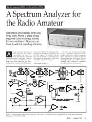
A Spectrum Analyzer for the Radio AmateurâPart 2
A Spectrum Analyzer for the Radio AmateurâPart 2
A Spectrum Analyzer for the Radio AmateurâPart 2

Create successful ePaper yourself
Turn your PDF publications into a flip-book with our unique Google optimized e-Paper software.
An inside view of a prototype VHF bandpass<br />
filter. See Figure 7.<br />
Figure 16—A 20-W, 20-dB attenuator <strong>for</strong> transmitter measurements.<br />
Figure 17—Block<br />
diagram <strong>for</strong> a version of<br />
this analyzer that will<br />
function into <strong>the</strong> VHF and<br />
low-UHF regions.<br />
logs and a Web browser could be very productive<br />
in this regard. Just as important is <strong>the</strong><br />
experience that <strong>the</strong> lower-frequency analyzer<br />
will provide. Not only is it <strong>the</strong> tool (perhaps<br />
supplemented with block converters) that is<br />
needed to build a higher-frequency spectrum<br />
analyzer, but it is <strong>the</strong> vehicle to provide <strong>the</strong><br />
confidence needed to tackle such a chore.<br />
Summary<br />
This analyzer has been a useful tool <strong>for</strong><br />
over 10 years now. It was a wonderful experience<br />
and fun to build HF and VHF CW<br />
and SSB gear with <strong>the</strong> “right” test equipment<br />
available. We have built special, narrow-tuning-range<br />
analyzers to examine<br />
transmitter sideband suppression and distortion.<br />
The equipment uses <strong>the</strong> same concepts<br />
presented.<br />
There are many ways that this instrument<br />
can grow. One builder has already breadboarded<br />
a tracking generator. (Let’s see that<br />
in QST!—Ed.) Many builders will want to<br />
interface <strong>the</strong> analyzer with a computer instead<br />
of an oscilloscope. A recent QST network<br />
analyzer paper suggests circuits that<br />
may provide such a solution. 21<br />
A recent QST summary of WRC97 22 outlines<br />
new specifications regarding spurious<br />
emissions from amateur transmitters. Gener-<br />
40 September 1998<br />
ally, <strong>the</strong> casual specifications that we have<br />
enjoyed <strong>for</strong> many years are being replaced by<br />
new ones that are more stringent—and more<br />
realistic in safeguarding <strong>the</strong> spectral environment<br />
and reflecting <strong>the</strong> sound designs that<br />
we all strive to achieve. Equipment such as<br />
<strong>the</strong> spectrum analyzer described here can<br />
provide <strong>the</strong> basic tool needed to meet this<br />
new challenge.<br />
Acknowledgments<br />
Many experimenters had a hand in this<br />
project and we owe <strong>the</strong>m our gratitude. Jeff<br />
Damm, WA7MLH, and Kurt Knoblock,<br />
WK7Q, built versions of <strong>the</strong> analyzer and<br />
have garnered several years of use with <strong>the</strong>m.<br />
Their experiences have been of great value in<br />
our ef<strong>for</strong>ts. Barrie Gilbert of Analog Devices<br />
Northwest Labs suggested <strong>the</strong> AD8307 log<br />
amplifier and provided samples and early<br />
data needed <strong>for</strong> evaluation measurements.<br />
Many of our colleagues within <strong>the</strong> Wireless<br />
Communications Division at TriQuint Semiconductor<br />
have helped us with filter measurements:<br />
Thanks go to George Steen and to<br />
Don Knotts, W7HJS. Finally, special thanks<br />
go to our colleague in <strong>the</strong> receiver group at<br />
TriQuint, Rick Campbell, KK7B, who provided<br />
numerous enlightening discussions<br />
and suggestions regarding <strong>the</strong> preparation of<br />
<strong>the</strong> paper and <strong>the</strong> role of measurements in<br />
amateur experiments.<br />
Notes<br />
14 Wes Hayward, W7ZOI, and Terry White,<br />
K7TAU, “A <strong>Spectrum</strong> <strong>Analyzer</strong> <strong>for</strong> <strong>the</strong> <strong>Radio</strong><br />
Amateur,” Part 1, QST, Aug 1998, pp 35-43.<br />
15 The wide-range oscillator presented in Fig 68,<br />
Chapter 7 of Solid-State Design <strong>for</strong> <strong>the</strong> <strong>Radio</strong><br />
Amateur (Newington: ARRL, 1997) is still intact<br />
and still often used.<br />
16 The term dBc refers to dB attenuation with<br />
respect to a specific carrier.<br />
17 Formally, this is <strong>the</strong> transducer gain, or 50-Ω<br />
insertion gain. There are many different parameters<br />
that are called “gain.”<br />
18 The signal sources used are updated versions<br />
of <strong>the</strong> circuits shown in Fig 66, p 168, in<br />
<strong>the</strong> Note 15 referent.<br />
19 See page 154, Solid-State Design <strong>for</strong> <strong>the</strong><br />
<strong>Radio</strong> Amateur.<br />
20 A 20-dB return loss corresponds to a voltage<br />
reflection coefficient of 0.1, or an SWR of<br />
1.222. See Wes Hayward, W7ZOI, Introduction<br />
to RF Design (Newington: ARRL, 1994),<br />
p 120.<br />
21 See, <strong>for</strong> example, Steven Hageman, “Build<br />
Your Own Network <strong>Analyzer</strong>,” QST, Jan<br />
1998, pp 39-45; Part 2, Feb 1998, pp 35-39.<br />
22 Larry Price, W4RA, and Paul Rinaldo, W4RI,<br />
“WRC97, An Amateur <strong>Radio</strong> Perspective,”<br />
QST, Feb 1998, pp 31-34. See also Rick<br />
Campbell, KK7B, “Unwanted Emissions<br />
Comments,” Technical Correspondence,<br />
QST, Jun 1998, pp 61-62.