DUCT HEATER CATALOG - Agencespl.com
DUCT HEATER CATALOG - Agencespl.com
DUCT HEATER CATALOG - Agencespl.com

You also want an ePaper? Increase the reach of your titles
YUMPU automatically turns print PDFs into web optimized ePapers that Google loves.
Page _____ of _____<br />
air through wall openings or ducts.<br />
Confined Space<br />
A space whose volume<br />
is less than 50 cubic<br />
feet per 1000 BTUH<br />
(1.5 cubic meters per<br />
kW) of the installed<br />
appliance input rating.<br />
C<br />
C<br />
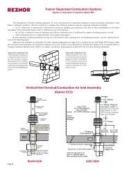
<strong>HEATER</strong>S LOCATED IN CONFINED SPACES<br />
Do not install unit in confined space without providing wall openings<br />
leading to and from this space. Provide adequate openings near floor and<br />
ceiling for ventilation and air for <strong>com</strong>bustion, as shown above, depending<br />
on <strong>com</strong>bustion air source as noted below.<br />
Add total BTUH of all appliances in the confined space and divide by<br />
figures below for square inch free area size of each (top and bottom) opening.<br />
1. Air from inside building - openings 1 square inch free area per 1,000<br />
BTUH. Never less than 100 square inches free area for each opening.<br />
See “A” in illustration.<br />
2. Air from outside through duct - openings 1 square inch free area per<br />
2,000 BTUH. See “B” in illustration.<br />
3. Air direct from outside - openings 1 square inch free area per 4,000<br />
BTUH. See “C” in illustration.<br />
NOTE: For further details on supplying <strong>com</strong>bustion air to confined space<br />
A<br />
Confined Space<br />
A<br />
B<br />
B<br />
see: National Fuel Gas Code ANSI Z223.1 - (latest edition) 5.3.3.<br />
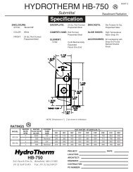
GAS PIPING AND PRESSURES<br />
To provide adequate gas pressure at the furnace, refer to pipe sizing<br />
tables. The unit is equipped for a maximum gas supply pressure of 1/2<br />
pound or 8 ounces. An additional service regulator external to the unit is<br />
required to reduce higher supply pressures to the 1/2 pound maximum.<br />
WARNING: Never expose gas control on unit to greater than<br />
1/2 pound pressure! Pressure testing of the gas supply piping<br />
system must be carried out before connecting the furnace.<br />
A pipe cap or field-supplied high pressure gas cock<br />
must be used during proof testing of the system.<br />
For Natural Gas<br />
Manifold pressure is regulated by the <strong>com</strong>bination valve to 3.5” water<br />
column. Line pressure upstream of the controls must be a minimum of<br />
5” water column or as noted on unit rating plate.<br />
For Propane Gas<br />
Manifold pressure is regulated by the <strong>com</strong>bination valve to 10” water<br />
column. Line pressure upstream of controls must be 11” water column<br />
minimum and 14” maximum.<br />
NOTE: Gas supply pressures higher than 14” w.c. or 1/2 pound require an<br />
additional service regulator to be added to the unit or supply system.<br />
All piping must be in accordance with requirements outlined in the National<br />
Fuel Gas Code ANSI Z223.1-(latest edition) or CAN/C.G.A.-B149<br />
(.1 or .2).<br />
When regulations require and for ease of servicing, install a ground joint<br />
union and manual shut-off valve upstream of unit control system.<br />
WARNING: All <strong>com</strong>ponents of gas supply system must be<br />
leak tested prior to placing equipment in service. NEVER TEST<br />
FOR LEAKS WITH AN OPEN FLAME.<br />
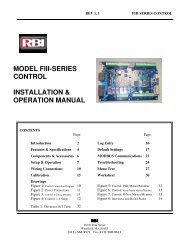
SIZING BY-PASS AIR <strong>DUCT</strong><br />
LIMIT CONTROL<br />
TOP VIEW<br />
EEDU<br />
FURNACE<br />
2” (50mm) MINIMUM<br />
COL. A<br />
WIDTH*<br />
BY-PASS <strong>DUCT</strong><br />
BY-PASS CFM<br />
Col. A<br />
Pressure Drop Through Heaters<br />
Width* 0.10 0.15 0.20 0.25 0.30 0.35 0.40 0.45 0.50<br />
3" 490 530 610 700 780 830 900 960 1010<br />
4" 630 750 870 980 1090 1160 1250 1310 1400<br />
5" 850 1010 1190 1300 1410 1520 1640 1730 1810<br />
6" 1050 1290 1480 1650 1800 1940 2090 2200 2320<br />
7" 1250 1510 1760 1960 2180 2320 2500 2650 2800<br />
8" 1490 1810 2100 2350 2560 2760 2940 3110 3920<br />
9" 1700 2100 2400 2700 2970 3200 3400 3600 3800<br />
10" 1920 2380 2760 3090 3650 4020 4300 4550 4800<br />
*Depth of by-pass duct is 18" on both inlet and outlet ends. NOTE: By-pass<br />
must be located on side opposite limit control and 2" from side panel.<br />
Note: Not all capabilities are covered in this chart. If your installation is<br />
not covered, the correct size may be determined by consulting your factory<br />
representative.<br />
Form RZ-C-DH Page 21<br />
Directions for Sizing By-Pass Duct<br />
1. From the Pressure Drop Tables on pages 20 and 21, find the pressure<br />
drop for the Model and Size of unit that is being installed and the allowable<br />
CFM.<br />
Example: EEDU 125 @ 70° temperature rise<br />
P.D. .25<br />
CFM 1315<br />
2. Subtract the allowable CFM from the actual CFM of the installation to<br />
determine how much air must go through the by-pass duct.<br />
Example: Blower CFM 3000<br />
Allowable CFM -1315<br />
By-Pass CFM 1685<br />
3. Go to the column in the By-Pass CFM Chart that is closest to the pressure<br />
drop. Move down in that column until you find the CFM closest to<br />
the answer in Step 2.<br />
Example: P.D. .25<br />
By-Pass CFM 1650<br />
4. Move to the left column to find out the required size of the by-pass duct.<br />
Example: By-Pass Duct<br />
Size is 6”<br />
Depth of the by-pass duct is 18” on both inlet and outlet ends. By-pass<br />
duct must be located on side opposite limit control and 2” from the heat<br />
exchanger side panel.