CyberScan PC 300 Instruction Manual - Eutech
CyberScan PC 300 Instruction Manual - Eutech
CyberScan PC 300 Instruction Manual - Eutech

You also want an ePaper? Increase the reach of your titles
YUMPU automatically turns print PDFs into web optimized ePapers that Google loves.
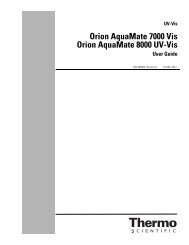
<strong>Instruction</strong> <strong>Manual</strong><br />
<strong>PC</strong> <strong>300</strong><br />
Waterproof Hand-held pH/Conductivity/TDS/Temperature Meter<br />
35631-00<br />
Technology Made Easy ...<br />
68X248908<br />
Rev3 01/04
Preface<br />
This manual serves to explain the use of the Waterproof <strong>PC</strong> <strong>300</strong> hand-held meter. It functions in<br />
two ways, firstly as a step by step guide to help you to operate the meter. Secondly, it serves as a<br />
handy reference guide. It is written to cover as many anticipated applications of the Waterproof <strong>PC</strong><br />
<strong>300</strong> hand-held meter as possible. If there are doubts in the use of the <strong>PC</strong> <strong>300</strong>, please do not<br />
hesitate to contact the nearest <strong>Eutech</strong> Instruments/ Oakton Instruments Authorized Distributor.<br />
<strong>Eutech</strong> Instruments/ Oakton Instruments cannot accept any responsibility for damage or<br />
malfunction to the meter caused by improper use of the instrument.<br />
The information presented in this manual is subject to change without notice as improvements are<br />
made, and does not represent a commitment on the part of <strong>Eutech</strong> Instruments Pte Ltd/ Oakton<br />
Instruments.<br />
Copyright © Feb 2000 All rights reserved.<br />
<strong>Eutech</strong> Instruments Pte Ltd/ Oakton Instruments<br />
Rev3 01/04
TABLE OF CONTENTS<br />
1 INTRODUCTION 1<br />
2 DISPLAY AND KEYPAD FUNCTIONS 2<br />
2.1 Display 2<br />
2.2 Keypad 3<br />
3 PREPARATION 4<br />
3.1 Inserting the Batteries 4<br />
3.2 Probe Information 5<br />
4 CALIBRATION 7<br />
4.1 Important Information on Meter Calibration 7<br />
4.2 Preparing the Meter for Calibration 8<br />
4.3 pH Calibration 8<br />
4.4 Conductivity Calibration 11<br />
4.5 TDS Calibration 14<br />
4.6 Calibration with Conductivity Standard and TDS factor 15<br />
4.7 Temperature Calibration 16<br />
5 MEASUREMENT 18<br />
5.1 Taking pH Measurements 18<br />
5.2 Taking Conductivity or TDS Measurement 22<br />
6 HOLD FUNCTION 28<br />
7 ADVANCED SETUP FUNCTIONS 29<br />
7.1 Advanced SETUP Mode Overview 31<br />
7.2 P1.0: Viewing previous pH calibration data 34<br />
7.3 P2.0: Viewing pH electrode data 35<br />
7.4 P3.0: pH Measurement configuration 36<br />
7.5 P4.0: Resetting to factory default settings (pH) 40<br />
7.6 P5.0: Viewing Previous Conductivity Calibration data 41<br />
7.7 P6.0: Viewing Conductivity Probe Data 42<br />
7.8 P7.0: Conductivity or TDS Measurement Configuration 43<br />
7.9 P8.0 Temperature 47<br />
8 PROBE CARE AND MAINTENANCE 50<br />
8.1 pH Electrode care 50<br />
8.2 Conductivity Electrode 52<br />
9 TROUBLE SHOOTING GUIDE 53<br />
10 ERROR MESSAGES 54<br />
11 SPECIFICATIONS 55<br />
12 ACCESSORIES 56<br />
13 ADDENDUM 1: CONDUCTIVITY TO TDS CONVERSION FACTORS 58<br />
14 ADDENDUM 2: CALCULATING TDS CONVERSION FACTORS 59<br />
15 ADDENDUM 3: CALCULATING TEMPERATURE COEFFICIENTS 60<br />
16 ADDENDUM 4: METER FACTORY DEFAULT SETTINGS 62<br />
17 ADDENDUM 5: SELECTING USA OR NIST BUFFER SET IN P3.3 63<br />
18 WARRANTY 64<br />
19 RETURN OF ITEMS 65
<strong>Instruction</strong> <strong>Manual</strong> <strong>PC</strong> <strong>300</strong><br />
1 INTRODUCTION<br />
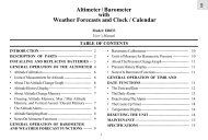
Thank you for selecting the <strong>PC</strong><strong>300</strong> waterproof portable meter. This meter is a microprocessorbased<br />
instrument that is designed to be handy capable of allowing one-hand operation. It is<br />
capable of measuring pH, Conductivity, TDS and Temperature. It is completely<br />
WATERPROOF --- and it FLOATS!<br />
This meter has many user-friendly features ---- all of which are completely accessible through<br />
the water-resistant membrane keypad. Your meter includes a conductivity electrode (cell<br />
constant K = 1.0) with built-in temperature sensor (Order Code: EC-CONSEN91W/ 35608-50),<br />
pH electrode (EC-FE72522-01B/ 35641-51) and batteries. Please read this manual thoroughly<br />
before operating your meter.<br />
Figure 1: <strong>PC</strong> <strong>300</strong> meter<br />
1
<strong>Instruction</strong> <strong>Manual</strong> <strong>PC</strong> <strong>300</strong><br />
2 DISPLAY AND KEYPAD FUNCTIONS<br />
2.1 Display<br />
The LCD has a primary and secondary display.<br />
• The primary display shows the measured pH, conductivity or TDS.<br />
• The secondary display shows the measured temperature.<br />
The display also shows error messages, keypad functions and program functions.<br />
See Figure 2.<br />
Figure 2: Full LCD Screen<br />
1. SETup mode indicator 8. micro-siemens indicator 15. Low battery indicator<br />
2. MEASurement mode<br />
indicator<br />
9. parts per thousand indicator 16. Probe indicator<br />
3. CALibration indicator 10. parts per million indicator 17. Calibration solution<br />
indicator<br />
4. mV indicator 11. Temperature indicator 18. Cell constant indicator<br />
5. % indicator 12. pH indicator 19. ON / OFF indicator<br />
6. pH measurement indicator 13. Automatic Temperature<br />
Compensation indicator<br />
20. HOLD indicator<br />
7. milli-Siemens indicator 14. ERRor indicator 21. READY indicator<br />
2
<strong>Instruction</strong> <strong>Manual</strong> <strong>PC</strong> <strong>300</strong><br />
2.2 Keypad<br />
The large membrane keypad makes the instrument easy to use. Each button, when pressed,<br />
has a corresponding graphic indicator on the LCD. See Figure 1. Some buttons have several<br />
functions depending on its mode of operation.<br />
Key<br />
ON/OFF<br />
HOLD<br />
MODE<br />
CAL/MEAS<br />
ENTER /<br />
RANGE<br />
Function<br />
Powers on and shuts off the meter. When you switch on the meter, the meter starts up<br />
in the mode that you last switched off from. For example, if you shut the meter off in<br />
conductivity measurement mode, the meter will be in conductivity measurement mode<br />
when you switch the meter on.<br />
Freezes the measured reading. To activate, press HOLD while in measurement mode.<br />
To release, press HOLD again.<br />
Selects the measurement parameter. Press MODE to toggle between pH or TDS or<br />
conductivity measurement mode.<br />
Toggles between Calibration and Measurement mode.<br />
1. If you are in pH measurement mode, press CAL/MEAS to enter pH calibration<br />
mode.<br />
2. If you are in conductivity measurement mode, press CAL/MEAS to enter<br />
conductivity calibration mode.<br />
3. If you are in TDS measurement mode, press CAL/MEAS to enter TDS<br />
measurement calibration mode.<br />
While in SETUP sub-menu, pressing CAL/MEAS once takes you out to the SETUP<br />
main menu and pressing CAL/MEAS second time takes you directly into the<br />
measurement mode.<br />
ENTER function: Press to confirm values in Calibration mode and to confirm selections<br />
in SETUP mode.<br />
RANGE function (for conductivity &TDS measurements only): Press to enter manual<br />
ranging function. The MEAS indicator blinks while in manual ranging function.<br />
/ In Calibration mode:<br />
During conductivity and TDS calibration, press to scroll through calibration values.<br />
In SETUP mode:<br />
Press to scroll through the setup subgroup programs.<br />
SETUP Takes you into the SETUP mode. This mode lets you customize meter preference and<br />
defaults, view calibration, electrode offset data, adjust for temperature coefficient and<br />
normalization temperature.<br />
3
<strong>Instruction</strong> <strong>Manual</strong> <strong>PC</strong> <strong>300</strong><br />
3 PREPARATION<br />
3.1 Inserting the Batteries<br />
Four AAA batteries are included with your meter.<br />
1. Use a Philips screwdriver to remove the two screws holding the battery cover.<br />
See Figure 3 below.<br />
2. Remove battery cover to expose batteries.<br />
3. Insert batteries. Follow the diagram inside the cover for correct polarity.<br />
4. Replace the battery cover into its original position using the two screws removed earlier.<br />
Figure 3 - Back panel of meter showing meter compartment<br />
4
<strong>Instruction</strong> <strong>Manual</strong> <strong>PC</strong> <strong>300</strong><br />
3.2 Probe Information<br />
Your meter includes two probes:<br />
• pH electrode with BNC connector.<br />
• conductivity/temperature probe with a notched 6-pin connector<br />
The temperature sensing element built into the conductivity probe will also compensate<br />
for pH readings as long as both probes are in your solution at the same time.<br />
If you want to use a “3-in1” pH probe with a built-in temperature element, or if you want to use<br />
a separate temperature probe, you will need to disconnect the conductivity probe to allow for<br />
connection of the separate temperature sensor.<br />
You can use any standard pH electrode with a BNC connector with this meter. Conductivity<br />
probes, “3-in-1” pH electrodes with a built-in temperature element, and temperature probes<br />
require a notched 6-pin connector (see Figure 4). For replacement probes, see the<br />
“Accessories” section.<br />
NOTE: Keep connector dry and clean. Do not touch connector with soiled hands.<br />
To connect the pH electrode:<br />
1. Slide the BNC connector of the probe over the BNC connector socket on the meter.<br />
Make sure the slots of the connector are in line with the posts of the socket. Rotate and<br />
push the connector clockwise until it locks.<br />
2. To remove electrode, push and rotate the connector anti-clockwise. While holding onto<br />
the metal part of the connector, pull it away from the meter.<br />
CAUTION: Do not pull on the probe cord or the probe wires might disconnect.<br />
5
<strong>Instruction</strong> <strong>Manual</strong> <strong>PC</strong> <strong>300</strong><br />
To connect the conductivity/temperature probe:<br />
1. Line up the notch and 6 pins on the probe connector with the holes in the connector<br />
located on the top of the meter. Push down and screw the metal sleeve to lock the probe<br />
connector into place. See Figure 4.<br />
2. To remove probe, unscrew the metal sleeve and slide up the probe connector. While<br />
holding onto metal sleeve, pull probe away from the meter.<br />
NOTE: Follow the same directions to connect an optional separate temperature element.<br />
CAUTION: Do not pull on the probe cord or the probe wires might disconnect.<br />
Figure 4: Connecting pH and conductivity/temperature probes<br />
6
<strong>Instruction</strong> <strong>Manual</strong> <strong>PC</strong> <strong>300</strong><br />
4 CALIBRATION<br />
4.1 Important Information on Meter Calibration<br />
When you re-calibrate your meter, old calibration points are replaced on a “point-by-point”<br />
basis in pH, and on a “range-by-range” basis in conductivity.<br />
For example:<br />
• pH: if you previously calibrated your meter at pH 4.01, 7.00, and 10.01, and<br />
you re-calibrate at pH 7.00, the meter retains the old calibration data at pH<br />
4.01 and pH 10.01.<br />
• Conductivity: If you previously calibrated your conductivity meter at 1413 µS<br />
in the 0 to 1999 µS range and you re-calibrate at 1500 µS (which is also in the<br />
0 to 1999 µS), the meter will replace the old calibration data (1413 µS) in that<br />
range. The meter will retain all calibration data in other ranges.<br />
• TDS: If you previously calibrated your conductivity meter at <strong>300</strong> ppm in the 0<br />
to 999 ppm range and you re-calibrate at 500 ppm (which is also in the 0 to<br />
999 ppm), the meter will replace the old calibration data (<strong>300</strong> ppm) in that<br />
range. The meter will retain all calibration data in other ranges.<br />
To view current calibration points:<br />
• pH: Program P1.0 in the SETUP section<br />
• Conductivity & TDS: Program P5.0 in the SETUP section<br />
To completely re-calibrate your meter, or when you use a replacement probe, it is best to<br />
delete the old calibration data by re-setting the meter.<br />
To reset the meter to its factory defaults:<br />
• pH: Program P4.0 in the SETUP section<br />
• Conductivity & TDS: Program P9.0 in the SETUP section<br />
NOTE: Re-setting the meter will set meter to factory defaults. Conductivity and pH must be<br />
reset separately.<br />
For directions on how to calibrate your meter:<br />
• See section 4.3 for pH calibration.<br />
• See section 4.4 for conductivity calibration.<br />
• See section 4.4 for TDS calibration.<br />
• See section 4.5 for Temperature calibration.<br />
7
<strong>Instruction</strong> <strong>Manual</strong> <strong>PC</strong> <strong>300</strong><br />
4.2 Preparing the Meter for Calibration<br />
Before starting calibration, make sure you are in the correct measurement mode. When you<br />
switch on the meter, the meter starts up in the measurement mode you shut it off in. For<br />
example, if you shut the meter off in pH measurement mode, the meter will come back into pH<br />
measurement mode when you switch the meter on.<br />
4.3 pH Calibration<br />
NOTE: We recommend that you perform at least 2-point calibration using standard<br />
buffers that bracket (one above and one below) the expected sample range.<br />
Preparing for pH calibration<br />
This meter is capable of up to 5-point pH calibration to ensure accuracy across the entire pH<br />
range of the meter. Select from the following buffer options:<br />
• pH 1.68, 4.01, 7.00, 10.01 and 12.45 (USA)<br />
• pH 1.68, 4.01, 6.86, 9.18, 12.45 (NIST)<br />
The meter automatically recognizes and calibrates to these standard buffer values, which<br />
makes pH calibration faster and easier.<br />
Be sure to remove the protective electrode storage bottle or rubber cap of the electrode<br />
before calibration or measurement. If the electrode has been stored dry, wet the electrode<br />
in tap water for 10 minutes before calibrating or taking readings to saturate the pH electrode<br />
surface and minimize drift.<br />
Wash your electrode in de-ionized water after use, and store in electrode storage solution. If<br />
storage solution is not available, use pH 4.01 or 7.00 buffer solution.<br />
Do not reuse buffer solutions after calibration. Contaminants in the solution can affect the<br />
calibration and eventually the accuracy of the measurements. See Section on Accessories for<br />
information on our high-quality pH buffer solutions.<br />
8
<strong>Instruction</strong> <strong>Manual</strong> <strong>PC</strong> <strong>300</strong><br />
To Calibrate pH:<br />
1. If necessary, press the MODE key to select pH<br />
mode. The pH indicator appears in the upper right<br />
hand corner of the display.<br />
2. Rinse the probe thoroughly with de-ionized water<br />
or a rinse solution. Do not wipe the probe; this<br />
causes a build-up of electrostatic charge on the<br />
glass surface.<br />
3. Dip the probe into the calibration buffer. The end of<br />
the probe must be completely immersed into the<br />
sample. Stir the probe gently to create a<br />
homogeneous sample.<br />
NOTE: The temperature element is in the conductivity<br />
cell. For temperature compensated readings, dip<br />
the conductivity cell into the calibration buffer as<br />
well.<br />
4. Press CAL/MEAS to enter pH calibration mode.<br />
The CAL indicator will be shown. The primary<br />
display will show the measured reading while the<br />
smaller secondary display will indicate the pH<br />
standard buffer solution.<br />
5. Wait for the measured pH value to stabilize. See<br />
Figure 5.<br />
Figure 5 - pH Calibration<br />
9
<strong>Instruction</strong> <strong>Manual</strong> <strong>PC</strong> <strong>300</strong><br />
6. Press ENTER to confirm calibration. The meter is<br />
now calibrated to the current buffer. The lower<br />
display scrolls through the remaining buffer options.<br />
• If you are performing multi-point calibration, go<br />
to step 7.<br />
• If you are performing one-point calibration, go<br />
to step 9.<br />
7. Rinse the electrode with de-ionized water or in rinse<br />
solution, and place it in the next pH buffer.<br />
8. Follow steps 5 to 8 for additional calibration points.<br />
See Figure 6.<br />
9. When calibration is complete, press CAL/MEAS to<br />
return to pH measurement mode.<br />
Figure 6 - Next point calibration for<br />
pH 4.01<br />
NOTES: To exit from pH calibration mode without<br />
confirming calibration, DO NOT press ENTER in<br />
step 6. Press CAL/MEAS instead.<br />
If the selected buffer value is not within ±1.0 pH from<br />
the measured pH value: the electrode and buffer icon<br />
blink and the ERR annunciator appears in the lower left<br />
corner of the display. See Figure 7.<br />
To limit the number of pH buffer values available during<br />
calibration, see SETUP section P3.2.<br />
Figure 7 - Err message and<br />
electrode icon will appear if<br />
incorrect buffer are used<br />
10
<strong>Instruction</strong> <strong>Manual</strong> <strong>PC</strong> <strong>300</strong><br />
4.4 Conductivity Calibration<br />
The <strong>PC</strong> <strong>300</strong> meter has five measuring ranges. You can calibrate one point in each of the<br />
measuring ranges (up to five points). If you are measuring values in more than one range,<br />
make sure to calibrate each of the ranges you are measuring. All new calibration data will<br />
over-ride existing stored calibration data for each measuring range you calibrate.<br />
• If you are measuring in ranges near to or greater than 20 mS (10 ppt), or<br />
near to or lower than 100 µS (50 ppm), calibrate the meter at least once<br />
a week to get specified ±1% F.S. accuracy.<br />
• If you are measuring in the mid ranges and you washed the probe in<br />
deionized water and stored it dry, calibrate the meter at least once a<br />
month.<br />
• If you take measurements at extreme temperatures, calibrate the meter<br />
at least once a week.<br />
Preparing for conductivity calibration<br />
For best results, select a standard value close to the sample value you are measuring.<br />
Alternatively use a calibration solution value that is approximately 2/3 the full-scale value of<br />
the measurement range you plan to use. For example, in the 0 to 1999 µS conductivity range,<br />
use a 1413 µS solution for calibration.<br />
Range<br />
indicator<br />
Conductivity<br />
Range<br />
Table 1 - Range Indicator and its corresponding ranges<br />
Recommended Calibration<br />
Solution Range<br />
TDS Range<br />
Recommended Calibration<br />
Solution Range<br />
r 1 0.00 19.99 µS 6.00 to 17.00 µS 0.00 9.99 ppm 3.00 to 8.50 ppm<br />
r 2 0.0 199.9 µS 60.0 to 170.0 µS 10.0 99.9 ppm 30.0 to 85.0 ppm<br />
r 3 0 1999 µS 600 to 1700 µS 100 999 ppm <strong>300</strong> to 850 ppm<br />
r 4 0.00 19.99 mS 6.00 to 17.00 mS 1.00 9.99 ppt 3.00 to 8.50 ppt<br />
r 5 0.0 199.9 mS 60.0 to 170.0 mS 10.0 200 ppt 30.0 to 170 ppt<br />
Temperature Coefficient: These meters are factory set to a temperature coefficient of 2.1%<br />
per °C. For most applications this will provide good results. See Program P8.1 in<br />
Section 7.9 to set the temperature coefficient to different value. See Addendum 3,<br />
“Calculating Temperature Coefficients” to determine the appropriate temperature<br />
coefficient for your solution.<br />
Normalization Temperature: The factory default value for normalization temperature is 25<br />
°C. If you need to normalize to a value other than 25 °C, see Program P8.2 in Section<br />
7.9.<br />
11
<strong>Instruction</strong> <strong>Manual</strong> <strong>PC</strong> <strong>300</strong><br />
Do not reuse calibration solutions after calibration. Contaminants in the solution can affect the<br />
calibration, and eventually the accuracy of the measurements. Use fresh calibration solution<br />
each time you calibrate your meter.<br />
All new calibration data will over-ride existing stored calibration data for each measuring range<br />
calibrated.<br />
Calibrating for Conductivity:<br />
1. If necessary, press the MODE key to select<br />
conductivity mode.<br />
2. Rinse the probe thoroughly with de-ionized water<br />
or a rinse solution, then rinse with a small amount<br />
of calibration standard.<br />
3. Dip the probe into the calibration standard.<br />
Immerse the probe tip beyond the upper steel<br />
band. Stir the probe gently to create a<br />
homogeneous sample. See Figure 8.<br />
4. Wait for the measured conductivity value to<br />
stabilize. If the READY indicator has been<br />
activated (SETUP program P7.1), the READY<br />
annunciator lights when the reading is stable.<br />
5. Press CAL/MEAS to enter conductivity or TDS<br />
calibration mode. The CAL indicator will appear in<br />
the upper right corner of the display.<br />
6. Press the or keys to change the value on the<br />
primary display to match the value of the<br />
calibration standard.<br />
7. Press ENTER to confirm calibration value. The<br />
meter returns to the MEAS (measurement) mode.<br />
8. Repeat steps 1 to 7 for other measuring ranges.<br />
See figure 8.<br />
Figure 8 - Conductivity Calibration<br />
12
<strong>Instruction</strong> <strong>Manual</strong> <strong>PC</strong> <strong>300</strong><br />
NOTES:<br />
When entering calibration mode, the meter will<br />
display the factory default value. If the meter<br />
was previously calibrated, the display may<br />
“jump” to the factory default value when<br />
switching from measurement to calibration<br />
mode.<br />
To exit from Conductivity calibration mode<br />
without confirming calibration, DO NOT<br />
press the ENTER key in step 7. Press<br />
CAL/MEAS instead. This will retain the<br />
meter’s old calibration data in the measuring<br />
range of the calibration.<br />
You can offset the conductivity reading up to<br />
± 40% from default setting. If your measured<br />
value differs by more than ± 40%, clean or<br />
replace probe as needed.<br />
Figure 9 - Proper Immersion of<br />
the conductivity probe<br />
<strong>Eutech</strong> Instruments/ Oakton Instruments offers a wide selection of high-quality calibration<br />
standards. See section on Accessories for more information.<br />
13
<strong>Instruction</strong> <strong>Manual</strong> <strong>PC</strong> <strong>300</strong><br />
4.5 TDS Calibration<br />
4.5.1 Calibrating for TDS directly<br />
The factory default setting for TDS conversion factor is<br />
0.5. If your solution has a different TDS factor, you can<br />
improve calibration accuracy by setting the TDS factor<br />
prior to calibration. See P7.4 for directions.<br />
1. If necessary, press the MODE key to select TDS<br />
mode.<br />
2. Rinse the probe thoroughly with de-ionized water or<br />
a rinse solution, then rinse with a small amount of<br />
calibration standard.<br />
3. Dip the probe into the calibration standard. Immerse<br />
the probe tip beyond the upper steel band. Stir the<br />
probe gently to create a homogeneous sample.<br />
Allow time for the reading to stabilize.<br />
4. Press CAL/MEAS to enter TDS calibration mode.<br />
The CAL indicator will appear in the upper right<br />
corner of the display.<br />
5. Press the or keys to change the value on the<br />
primary display to match the value of the calibration<br />
standard.<br />
6. Press ENTER to confirm the calibration value. The<br />
meter returns to the MEAS (measurement) mode.<br />
See Figure 10.<br />
7. Repeat steps 1 to 6 for other measuring ranges.<br />
NOTES<br />
To exit from TDS Calibration mode without confirming<br />
calibration, DO NOT press the ENTER key in step 6.<br />
Press CAL/MEAS instead. This will retain the meter’s old<br />
calibration data in the measuring range of the calibration.<br />
You can offset the TDS reading up to ± 20% from the<br />
default setting. If your measured value differs by more<br />
than ± 40%, clean or replace probe as needed.<br />
Figure 10 - TDS Calibration<br />
14
<strong>Instruction</strong> <strong>Manual</strong> <strong>PC</strong> <strong>300</strong><br />
4.6 Calibration with Conductivity Standard and TDS factor<br />
The concentration of salts dissolved in solution increases the conductivity of that solution. This<br />
relationship varies from salt to salt and is roughly linear over a given range for a given salt.<br />
The TDS conversion factor is the number used by the meter to convert from conductivity to<br />
TDS.<br />
Instead of calibrating for TDS directly (described above), you can calibrate the <strong>PC</strong> <strong>300</strong> meter<br />
by:<br />
1. calibrating to conductivity standards (as described above) and then<br />
2. entering the appropriate TDS conversion factor into the meter.<br />
To determine the conductivity to TDS conversion factor for your solution:<br />
• Addendum 1 lists some commonly used conversion factors.<br />
• Addendum 2 describes how to calculate the TDS conversion factor for other<br />
solutions.<br />
Enter the TDS conversion factor into your meter as described under Section 7.5, in P7.4<br />
Setting the TDS Factor.<br />
15
<strong>Instruction</strong> <strong>Manual</strong> <strong>PC</strong> <strong>300</strong><br />
4.7 Temperature Calibration<br />
The conductivity electrode (EC-CONSEN91W/ 35608-50)<br />
supplied with the meter has a built-in temperature sensor. In<br />
addition you can also use a separate temperature sensing<br />
element supplied by <strong>Eutech</strong> Instruments (as such<br />
temperature probe (EC-PHWPTEMP-01W/ 35618-05), or the<br />
“3-in-1” pH/Temperature combination electrode, (EC-<br />
FE73528-01W/ 35808-71) for ATC purpose.<br />
The conductivity probe is factory calibrated. Temperature<br />
calibration can be done only if you suspect temperature<br />
errors that may have occurred over a long period of time, or if<br />
you have a replacement probe.<br />
Temperature calibration is accessible during pH or<br />
conductivity or TDS calibration.<br />
Temperature Calibration<br />
1. Make sure the conductivity electrode (or temperature<br />
probe or “3-in-1” electrode) is attached to the 6-pin<br />
connector.<br />
2. Switch the meter on.<br />
3. Press the CAL/MEAS key to enter calibration mode<br />
(either from pH or conductivity mode). The CAL<br />
indicator will appear above the primary display.<br />
4. While in pH (or conductivity or TDS) calibration mode,<br />
press the MODE key to enter temperature calibration<br />
mode. The primary display shows the last set<br />
temperature value and the secondary display shows the<br />
temperature reading with zero offset.<br />
5. Dip the ATC probe into a solution of known temperature<br />
(i.e. a temperature bath). Allow time for the temperature<br />
probe to stabilize.<br />
Figure 11 - Temperature<br />
Calibration in pH mode.<br />
16
<strong>Instruction</strong> <strong>Manual</strong> <strong>PC</strong> <strong>300</strong><br />
6. Scroll with the and keys to set the correct temperature value (i.e. the temperature of<br />
the temperature bath). You can adjust the reading increments of 0.1 °C.<br />
7. Once you have selected the correct temperature press the ENTER key. The meter<br />
automatically returns to pH measurement mode. See Figure 11.<br />
NOTES:<br />
• You can offset the temperature reading up to ±5 °C from original reading.<br />
• To exit this program without confirming the temperature calibration value,<br />
DO NOT press ENTER. Press CAL/MEAS instead.<br />
17
<strong>Instruction</strong> <strong>Manual</strong> <strong>PC</strong> <strong>300</strong><br />
5 MEASUREMENT<br />
5.1 Taking pH Measurements<br />
5.1.1 Automatic Temperature Compensation<br />
Automatic Temperature Compensation only occurs when a<br />
temperature sensing element is plugged into the meter.<br />
Temperature sensing element refers to the following probes<br />
made specifically for this meter:<br />
• The conductivity electrode (EC-CONSEN91W/<br />
35608-50) with a built-in temperature sensor;<br />
• Temperature probe (EC-PHWPTEMP-01W/<br />
35618-05); or<br />
Figure 12 - ATC annunciator will<br />
light up when connected to<br />
temperature probe<br />
• The “3-in-1” pH/Temperature combination<br />
electrode (EC-FE73528-01W/ 35808-71).<br />
If there is no temperature sensor plugged into the meter, the default manual temperature<br />
setting is automatically 25 °C. You can manually set the temperature to match your working<br />
conditions using a separate thermometer.<br />
For automatic temperature compensation (ATC) simply plug the temperature probe into the<br />
meter (see page 6 for directions). The ATC indicator will light up on the LCD. See figure 12.<br />
NOTE: The temperature sensing element must be submersed in the liquid you are<br />
measuring.<br />
18
<strong>Instruction</strong> <strong>Manual</strong> <strong>PC</strong> <strong>300</strong><br />
5.1.2 <strong>Manual</strong> Temperature Compensation (pH)<br />
IMPORTANT: For manual compensation, you must<br />
disconnect the temperature probe (see section 3.2: Probe<br />
Information).<br />
1. Switch the meter on. Press the MODE key to select<br />
pH mode.<br />
2. Press the CAL/MEAS key to enter pH calibration<br />
mode. The CAL indicator will appear above the<br />
primary display.<br />
3. While in pH calibration mode, press the MODE key to<br />
enter temperature calibration mode. The primary<br />
display shows the current temperature setting and the<br />
secondary display shows the default value 25 °C.<br />
4. Check the temperature of your sample using an<br />
accurate thermometer.<br />
5. Press the or keys to set the temperature to the<br />
measured value from step 4.<br />
6. Press ENTER to confirm the selected temperature<br />
and to return to the pH measurement mode.<br />
See Figure 13.<br />
The meter will now compensate pH readings for the<br />
manually set temperature.<br />
Figure 13 - <strong>Manual</strong> temperature<br />
compensation<br />
NOTES:<br />
To exit this program without confirming the manual temperature compensation value, DO NOT<br />
press ENTER in step 6. Press CAL/MEAS instead.<br />
19
<strong>Instruction</strong> <strong>Manual</strong> <strong>PC</strong> <strong>300</strong><br />
5.1.3 Taking Measurements (pH)<br />
Be sure to remove the electrode soaker bottle or<br />
protective rubber cap on the electrode before<br />
measurement.<br />
To take readings:<br />
1. Rinse the pH electrode with de-ionized or distilled<br />
water before use to remove any impurities<br />
adhering to the probe body. If the pH electrode<br />
has dehydrated, soak it for 30 minutes in <strong>Eutech</strong><br />
Instruments electrode storage solution or 2M –<br />
4M KCl solution (sold separately).<br />
Figure 14 - Measurement mode<br />
2. Press ON to switch on meter.<br />
3. Press the MODE key to select pH measurement mode. The MEAS annunciator appears<br />
on the top center of the LCD. The ATC indicator appears in the lower right-hand corner to<br />
indicator Automatic Temperature Compensation.<br />
NOTE: For pH manual temperature compensation, you must disconnect the conductivity cell<br />
from the 6-pin connector. The ATC indicator will disappear from the display. You also need to<br />
set a manual temperature compensation value. See Section 5.1.2 to set <strong>Manual</strong> Temperature<br />
Compensation.<br />
4. Dip the probe into the sample. Since the conductivity cell contains the temperature<br />
sensor, make sure it is also immersed in your solution.<br />
When dipping the probe into the sample, the sensor or the glass bulb of the electrode must be<br />
completely immersed into the sample. Stir the probe gently in the sample to create a<br />
homogeneous sample.<br />
5. Allow time for the reading to stabilize. Note the reading on the display. Note the reading<br />
on the display. If the Ready indicator is selected on, it will appear when the reading is<br />
stable.<br />
20
<strong>Instruction</strong> <strong>Manual</strong> <strong>PC</strong> <strong>300</strong><br />
Taking measurements with READY indicator selected on<br />
If the READY indicator has been activated, the READY annunciator lights when the reading is<br />
stable*. Switch the READY indicator on or off in SETUP program P3.1. See Section 7.4.<br />
* The READY indicator appears and the reading holds until the measured value exceeds the<br />
tolerance (±0.02 pH; ± 0.8 mV 400). Then, the READY annunciator turns<br />
off.<br />
Taking measurements with the auto endpoint feature selected on<br />
When a reading is stable for more than 5 seconds, the auto endpoint feature will automatically<br />
“HOLD” the reading. The “HOLD” indicator appears on the left side of the display. Press the<br />
HOLD key to release the reading. Switch the Auto endpoint feature on or off in SETUP<br />
program P 3.1, see Section 7.4.<br />
21
<strong>Instruction</strong> <strong>Manual</strong> <strong>PC</strong> <strong>300</strong><br />
5.2 Taking Conductivity or TDS Measurement<br />
5.2.1 Automatic Temperature Compensation<br />
For automatic temperature compensation (ATC) simply<br />
plug the conductivity probe into the meter (see page 6 for<br />
directions). The ATC indicator will light on the LCD.<br />
NOTE: If the ATC indicator does not light, manual<br />
temperature compensation may be selected in<br />
the meter’s SETUP mode. See Program P7.3 in<br />
Section 7.8 for directions on selecting Automatic<br />
Temperature Compensation.<br />
Figure 15 - ATC annunciator will<br />
light up when connected to<br />
temperature probe<br />
5.2.2 <strong>Manual</strong> Temperature Compensation<br />
IMPORTANT: For manual compensation, you must deactivate the temperature probe.<br />
Selecting <strong>Manual</strong> Temperature Compensation for conductivity<br />
Selecting between Automatic Temperature<br />
Compensation (ATC) and <strong>Manual</strong> Temperature<br />
Compensation in the SETUP program P7.3 on in<br />
Section 7.8. Meter default is ATC on.<br />
From Conductivity or TDS measurement mode<br />
Figure 16 - P7.0 Configuration Setup<br />
for conductivity & TDS<br />
1) Press SETUP key to enter Set Up mode.<br />
2) Press the or keys keys to scroll through subgroups until you view parameter P7.0.<br />
See Figure 16.<br />
3) Press the ENTER key three times to select parameter 7.3. The upper display shows “ATC”<br />
and the lower display shows “P7.3”.<br />
4) Press the ENTER key again. The upper display shows “ATC” and the lower display shows<br />
“YES” or “NO”.<br />
22
<strong>Instruction</strong> <strong>Manual</strong> <strong>PC</strong> <strong>300</strong><br />
5) Press the or keys to select the Automatic<br />
Temperature Compensation feature on (ATC on) or<br />
off (ATC off). See Figure 18.<br />
6) Press the ENTER key to confirm selection and to<br />
return to the subgroup menu. Press the<br />
CAL/MEAS key to return to measurement mode.<br />
Note that the ATC indicator no longer appears on the<br />
display.<br />
Proceed to next section to select a manual temperature<br />
compensation value.<br />
Figure 18 - Turning ATC feature<br />
ON or OFF<br />
23
<strong>Instruction</strong> <strong>Manual</strong> <strong>PC</strong> <strong>300</strong><br />
5.2.3 Setting a manual temperature compensation value<br />
To use manual temperature compensation, you need to enter the temperature value of your<br />
process into the meter. This is the value at which reading will manually temperature<br />
compensates. You can select any temperature between 0 and 100 °C (32 to 212 °F). Default<br />
value is 25 °C (77 °F).<br />
To select a manual temperature compensation value<br />
1. Switch the meter on. Press the MODE key to select<br />
conductivity or TDS measurement mode.<br />
2. If necessary, select ATC off as described in section<br />
5.2.2. The ATC indicator will not appear on the<br />
display.<br />
3. Press the CAL/MEAS key to enter conductivity or<br />
TDS calibration mode. The CAL indicator will<br />
appear above the primary display.<br />
4. While in conductivity (or TDS) calibration mode,<br />
press the MODE key to enter temperature<br />
calibration mode. The primary display shows the<br />
current temperature setting and the secondary<br />
display shows the default value 25 °C (77 °F) or its<br />
last set value.<br />
5. Check the temperature of your sample using an<br />
accurate thermometer.<br />
6. Press the or keys to offset the temperature to<br />
the measured value from step 5.<br />
7. Press ENTER to confirm the selected temperature<br />
and to return to the conductivity measurement<br />
mode. See Figure 19.<br />
The meter will now compensate conductivity or TDS<br />
readings for manually set temperature.<br />
Figure 19 - <strong>Manual</strong> Temperature<br />
Compensation<br />
NOTES:<br />
To exit this program without confirming the manual temperature compensation value, DO NOT<br />
press ENTER in step 6. Press CAL/MEAS instead.<br />
Setting the manual temperature compensation value for conductivity will change the manual<br />
temperature compensation value for pH to the same value, and vice versa.<br />
24
<strong>Instruction</strong> <strong>Manual</strong> <strong>PC</strong> <strong>300</strong><br />
5.2.4 Taking Measurements (Conductivity or TDS)<br />
To take readings:<br />
1. Rinse the probe with de-ionized or distilled water<br />
before use to remove any impurities adhering to the<br />
probe body. Shake or air dry. To avoid contamination<br />
or dilution of your sample, rinse probe with a small<br />
volume of your sample liquid.<br />
2. Press ON to switch on meter.<br />
Figure 20 - During measurement<br />
3. Press the MODE key to select conductivity or TDS measurement mode. The MEAS<br />
annunciator appears on the top center of the LCD. The ATC indicator appears in the<br />
lower right hand corner to indicate Automatic Temperature Compensation.<br />
• NOTE: For conductivity manual temperature compensation, you must<br />
de-activate the temperature sensor built into the conductivity probe and<br />
set manual temperature compensation. See Section 5.2 for more<br />
information. The ATC indicator will disappear from the display.<br />
4. Dip the probe into the sample.<br />
When dipping the probe into the sample, take care to ensure that the liquid<br />
level is above its upper steel band. Stir the probe gently in the sample to<br />
create a homogenous sample. See Figure 9 in Section 4.4.<br />
5. Allow time for the reading to stabilize. Note the reading on the display. If the READY I<br />
indicator is selected on, it will appear when the reading is stable. See P7.1 in Section 7.8<br />
for more information.<br />
6. Press the MODE key to toggle between conductivity, TDS and pH readings.<br />
NOTES: You can use the conductivity manual ranging function to select a specific range in which<br />
your readings will appear. See Section 5.2.5: <strong>Manual</strong> ranging for directions.<br />
Taking measurements with READY indicator selected on<br />
If the READY indicator has been activated, the READY annunciator lights when the reading is<br />
stable*. Switch the READY indicator on or off in SETUP program P 7.1. See Section 7.8 for<br />
directions.<br />
Taking measurements with the auto endpoint feature selected on<br />
When a reading is stable for more than 5 seconds, the auto endpoint feature will automatically<br />
“HOLD” the reading. The “HOLD” indicator appears on the left side of the display. Press the<br />
HOLD key to release the reading. Switch the Auto endpoint feature on or off in SETUP<br />
program P 7.1, See Section 7.8 for directions.<br />
25
<strong>Instruction</strong> <strong>Manual</strong> <strong>PC</strong> <strong>300</strong><br />
5.2.5 Using Auto and <strong>Manual</strong> Ranging Function (for conductivity & TDS)<br />
Auto-ranging<br />
Your meter automatically selects the range in which your<br />
readings appear. For example:<br />
1. If you dip the conductivity probe into a standard solution,<br />
say, 12.88 mS.<br />
2. It will automatically select the most appropriate range,<br />
r 4, which is 0.00 to 19.99 mS (refer to Table 1 in<br />
Section 4.4).<br />
3. The secondary display on the LCD will momentarily<br />
display r 4 before it switches to measured temperature<br />
value.<br />
4. The primary display will show the actual conductivity<br />
value. See Figure 21.<br />
Figure 21 - Auto-ranging<br />
feature<br />
26
<strong>Instruction</strong> <strong>Manual</strong> <strong>PC</strong> <strong>300</strong><br />
<strong>Manual</strong>-ranging<br />
The manual ranging function lets you select the specific range<br />
you want to work in. Refer to Section 4.4 for the table of range.<br />
1. To select the desired measuring range, press the<br />
RANGE key while in Measurement mode. The first range<br />
will appear on the display and the “MEAS” indicator<br />
blinks. See Figure 22.<br />
2. Press the RANGE key again (if needed) until desired<br />
range is selected.<br />
3. To re-select the Auto-ranging function, repeatedly press<br />
the RANGE key until the “MEAS” indicator appears<br />
without blinking.<br />
Figure 22 - <strong>Manual</strong> ranging<br />
NOTES<br />
If the value of the solution you are measuring is higher than<br />
the range selected “Or” will appear on the primary display.<br />
Press RANGE until the correct range is selected.<br />
The meter resets to the Auto-ranging function once it is turned<br />
off. You will have reset the manual ranging function each time<br />
you turn the meter off.<br />
Figure 23 - Out-of-range<br />
27
<strong>Instruction</strong> <strong>Manual</strong> <strong>PC</strong> <strong>300</strong><br />
6 HOLD FUNCTION<br />
This feature lets you freeze the display for a delayed observation. HOLD can be used any time<br />
in MEAS mode.<br />
1. To hold a measurement, press the HOLD key while<br />
in measurement mode. “HOLD” will appear on the<br />
display.<br />
2. To release the held value, press the HOLD again.<br />
Continue to take measurements.<br />
Figure 24 - HOLD function<br />
NOTE:<br />
• This meter shuts off automatically after 20 minutes of last key press.<br />
• If the meter is shut off either automatically or manually, the HOLD value will be lost.<br />
• Your meter has an auto endpoint feature. When this feature is switched on, and<br />
when a reading is stable for more than 5 seconds, the display will automatically<br />
“HOLD” the reading. The “HOLD” indicator appears. Press the HOLD key to release<br />
the reading. To switch on or off the auto endpoint feature, see SETUP program P3.1<br />
in Section 7.4 for pH and SETUP, program P7.1 in Section 7.8 for conductivity/TDS.<br />
28
<strong>Instruction</strong> <strong>Manual</strong> <strong>PC</strong> <strong>300</strong><br />
7 ADVANCED SETUP FUNCTIONS<br />
The advanced setup mode lets you customized your meter’s preferences and defaults. This<br />
Waterproof handheld meter features different sub-groups that organize setup parameters.<br />
The sub-groups are:<br />
For pH<br />
For Conductivity & TDS<br />
P 1.0 View calibration data (CAL) P 5.0 View calibration data (CAL)<br />
P 2.0 View electrode data (ELE) P 6.0 View electrode data (ELE)<br />
P 3.0 Unit Configuration (COF) P 7.0 Unit Configuration (COF)<br />
P 4.0 Reset to factory default<br />
settings (rSt)<br />
P 8.0<br />
Temperature (tPr)<br />
P 9.0 Reset to factory default<br />
settings (rSt)<br />
See Figure 25 on next page.<br />
29
<strong>Instruction</strong> <strong>Manual</strong> <strong>PC</strong> <strong>300</strong><br />
Figure 25 - Overall view of SETUP programs for pH (on left) and conductivity/TDS (on right)<br />
30
<strong>Instruction</strong> <strong>Manual</strong> <strong>PC</strong> <strong>300</strong><br />
7.1 Advanced SETUP Mode Overview<br />
1. In either pH or Conductivity measurement mode, press the SETUP key to enter Set up<br />
mode.<br />
2. Press the or keys to scroll through sub groups.<br />
3. Press ENTER key to enter a particular parameter.<br />
See Addendum 4 for a table of meter factory default settings.<br />
SETUP in pH Measurement Mode<br />
P1.0: View previous calibration data<br />
P1.1 First calibration point (pH 1.68)<br />
P1.2 Second calibration point (pH 4.01)<br />
P1.3 Third calibration point (pH 7.00 or 6.86)<br />
P1.4 Fourth calibration point (pH 10.01 or 9.18)<br />
P1.5 Fifth calibration point (pH 12.45)<br />
<strong>Instruction</strong>s on Section 7.2.<br />
P2.0: View electrode data<br />
P2.1 pH electrode offset<br />
P2.2 pH electrode slope<br />
<strong>Instruction</strong>s in Section 7.3.<br />
P3.0: Unit configuration<br />
P3.1 READY indicator and auto endpoint function<br />
– select on or off<br />
P3.2 Number of pH calibration points: 2, 3, 4 or 5<br />
P3.3 Select buffer group: USA or NIST<br />
P3.4 Select °C or °F<br />
<strong>Instruction</strong>s in Section 7.4.<br />
P4.0: Reset to factory defaults<br />
P4.0 Reset meter to factory defaults<br />
<strong>Instruction</strong>s in Section 7.5.<br />
31
<strong>Instruction</strong> <strong>Manual</strong> <strong>PC</strong> <strong>300</strong><br />
SETUP in Conductivity Measurement Mode<br />
P5.0: View previous calibration data<br />
P5.1 First range calibration point (0.00 – 19.99 µS)<br />
P5.2 Second range calibration point (0.0 – 199.9 µS)<br />
P5.3 Third range calibration point (0 – 1999 µS)<br />
P5.4 Fourth range calibration point (0.00 – 19.99 mS)<br />
P5.5 Fifth range calibration point (0.0 – 199.9 mS)<br />
<strong>Instruction</strong>s in Section 7.6.<br />
P6.0: View electrode data<br />
P6.1 Effective cell constant for first range<br />
(0.00 – 19.99 µS)<br />
P6.2 Effective cell constant for second range<br />
(0.0 – 199.9 µS)<br />
P6.3 Effective cell constant for third range (0 – 1999 µS)<br />
P6.4 Effective cell constant for fourth range<br />
(0.00 – 19.99 mS)<br />
P6.5 Effective cell constant for fifth range<br />
(0.0 – 199.9 mS)<br />
<strong>Instruction</strong>s in Section 7.7.<br />
P7.0: Unit configuration<br />
P7.1 READY indicator and auto endpoint function –<br />
select on or off<br />
P7.2 Select °C or °F<br />
P7.3 Select Automatic or <strong>Manual</strong> Temperature<br />
Compensation<br />
P7.4 Setting TDS conversion factor<br />
<strong>Instruction</strong>s in Section 7.8.<br />
P8.0: Temperature<br />
P8.1 Adjusting temperature coefficient<br />
P8.2 Adjusting normalization temperature<br />
<strong>Instruction</strong>s in Section 7.9.<br />
P9.0: Reset to factory defaults<br />
P9.0 Reset meter to factory defaults<br />
<strong>Instruction</strong>s in Section 7.9.1.<br />
32
<strong>Instruction</strong> <strong>Manual</strong> <strong>PC</strong> <strong>300</strong><br />
SETUP in TDS Measurement Mode<br />
P5.0: View previous calibration data<br />
P5.1 First range calibration point (0.00 – 9.99 ppm)<br />
P5.2 Second range calibration point (0.0 – 99.9 ppm)<br />
P5.3 Third range calibration point (0 – 999 ppm)<br />
P5.4 Fourth range calibration point (0.00 – 9.99 ppt)<br />
P5.5 Fifth range calibration point (0.0 – 200 ppt)<br />
<strong>Instruction</strong>s in Section 7.6.<br />
P6.0: View electrode data<br />
P6.1 Effective cell constant for first range<br />
(0.00 – 9.99 ppm)<br />
P6.2 Effective cell constant for second range<br />
(0.0 – 99.9 ppm)<br />
P6.3 Effective cell constant for third range (0 – 999 ppm)<br />
P6.4 Effective cell constant for fourth range<br />
(0.00 – 9.99 ppt)<br />
P6.5 Effective cell constant for fifth range<br />
(0.0 – 200 ppt)<br />
<strong>Instruction</strong>s in Section 7.7.<br />
P7.0: Unit configuration<br />
P7.1 READY indicator and auto endpoint function –<br />
select on or off<br />
P7.2 Select °C or °F<br />
P7.3 Select Automatic or <strong>Manual</strong> Temperature<br />
Compensation<br />
P7.4 Setting TDS conversion factor<br />
<strong>Instruction</strong>s in Section 7.8.<br />
P8.0: Temperature<br />
P8.1 Adjusting temperature coefficient<br />
P8.2 Adjusting normalization temperature<br />
<strong>Instruction</strong>s in Section 7.9.<br />
P9.0: Reset to factory defaults<br />
P9.0 Reset meter to factory defaults<br />
<strong>Instruction</strong>s in Section 7.9.1.<br />
33
<strong>Instruction</strong> <strong>Manual</strong> <strong>PC</strong> <strong>300</strong><br />
7.2 P1.0: Viewing previous pH calibration data<br />
This mode lets you recall previous pH calibration data, which helps you know when to recalibrate<br />
your meter. This is a “view only” mode.<br />
From measurement mode:<br />
1. Press the MODE key to select pH measurement<br />
mode if necessary.<br />
2. Press the SETUP key to enter Set up mode.<br />
3. Press the or keys to scroll through subgroups<br />
until you view parameter P1.0.<br />
4. Press the ENTER key repeatedly to view previous<br />
calibration data. See Figure 26.<br />
USA<br />
NIST<br />
• P1.1 = pH 1.68 1.68<br />
• P1.2 = pH 4.01 4.01<br />
• P1.3 = pH 7.00 6.86<br />
• P1.4 = pH 10.01 9.18<br />
• P1.5 = pH 12.45 12.45<br />
5. When you have scrolled through all calibration data,<br />
you will automatically return to the subgroup menu.<br />
Press CAL/MEAS key to return to measurement<br />
mode.<br />
Figure 26 – P1.0: View calibration<br />
data for pH<br />
NOTES:<br />
If there is no previous calibration data at a particular point, the primary display will show “- - -“.<br />
34
<strong>Instruction</strong> <strong>Manual</strong> <strong>PC</strong> <strong>300</strong><br />
7.3 P2.0: Viewing pH electrode data<br />
Program 2 has two “view only” options that let you check<br />
the electrode parameters for diagnostic purposes. It lets<br />
you view:<br />
• P2.1 = Electrode offset<br />
• P2.2 = Electrode slope<br />
From pH measurement mode<br />
1. Press the MODE key to select pH measurement<br />
mode.<br />
2. Press the SETUP key to enter Set Up mode.<br />
3. Press the or keys to scroll through subgroups<br />
until you view parameter P2.0.<br />
4. Press the ENTER key to select parameter 2.1.<br />
5. The display shows the electrode offset value. It is the<br />
mV offset at pH 7.00. If you have not calibrated at any<br />
buffer, the primary display shows 0.00 mV.<br />
6. Press the ENTER key to proceed to P2.2.<br />
7. The display shows electrode slope in percentage.<br />
Slope displayed is the average slope based on the pH<br />
calibrations. Default setting is 100.0.<br />
8. At any point, you can press the CAL/MEAS key to<br />
return to measurement mode.<br />
Figure 27 - Viewing electrode's<br />
offset and slope status from pH<br />
measurement mode<br />
See Figure 27.<br />
(The values shown above are for illustration purpose. Your meter may display different values depending on<br />
the settings & your environmental conditions)<br />
35
<strong>Instruction</strong> <strong>Manual</strong> <strong>PC</strong> <strong>300</strong><br />
7.4 P3.0: pH Measurement configuration<br />
This subgroup program allows to customize the meter to<br />
your specific needs. You can program the meter to:<br />
1. Select READY indicator ON or OFF<br />
2. Select the number of pH calibration points<br />
SETUP<br />
cof<br />
p3.0<br />
pH<br />
3. Select between USA and NIST buffers<br />
4. Select between °C and °F units for temperature<br />
readings<br />
SETUP<br />
READY<br />
ENTER<br />
RANGE<br />
Figure 28 on the right shows the setup sequence for this<br />
program subgroup.<br />
ON<br />
p3.1<br />
ENTER<br />
RANGE<br />
SETUP<br />
READY<br />
ON<br />
3 p<br />
p3.2<br />
ENTER<br />
RANGE<br />
SETUP<br />
usa<br />
p3.3<br />
ENTER<br />
RANGE<br />
SETUP<br />
C<br />
p3.4 °C<br />
Figure 28 – P 3.0: Unit<br />
configuration program<br />
36
<strong>Instruction</strong> <strong>Manual</strong> <strong>PC</strong> <strong>300</strong><br />
P3.1: READY Indicator and auto endpoint function<br />
This program lets you select:<br />
• “READY indicator on” to indicate when the reading<br />
is stable.<br />
• “READY indicator off” for faster meter response.<br />
• Auto endpoint function on. Select auto endpoint<br />
on to “hold” the reading when it is stable for more<br />
than 5 seconds. The display automatically freezes,<br />
and the HOLD indicator appears on the left side of<br />
the display. Press the HOLD key to release the<br />
display and access other functions.<br />
From measurement mode<br />
1. Press the MODE key to select pH measurement<br />
mode.<br />
2. Press SETUP key to enter Set Up mode.<br />
3. Press the or keys to scroll through subgroups<br />
until you view parameter P3.0.<br />
4. Press the ENTER key to select parameter 3.1.<br />
5. Press the or keys to select the configuration<br />
you require.<br />
• OFF switches the READY indicatory off.<br />
• ON switches the READY indicator on.<br />
• ON and HOLD together switches the auto<br />
endpoint feature on.<br />
6. Press the ENTER key to confirm selection and to<br />
proceed to step 4 of P3.2. Press the CAL/MEAS<br />
key to return to measurement mode.<br />
Figure 29 – P 3.1: Selecting<br />
READY function)<br />
NOTES:<br />
Meter default is set for READY indicator on and auto endpoint function off.<br />
37
<strong>Instruction</strong> <strong>Manual</strong> <strong>PC</strong> <strong>300</strong><br />
You can also change the Ready indicator and auto endpoint function in Program P7.1<br />
(available from conductivity or TDS mode). Any changes you make to the Ready indicator/auto<br />
endpoint function in pH mode will also change in conductivity mode.<br />
P3.2: Selecting number of pH calibration points<br />
Program P3.2 lets you select the number of calibration<br />
points that appear in pH calibration mode: 2, 3, 4, or 5.<br />
The meter will automatically exit calibration mode after<br />
you have calibrated to your selected number of points.<br />
From measurement mode.<br />
1. Press the MODE key to select pH measurement<br />
mode.<br />
2. Press SETUP key to enter Set Up mode.<br />
3. Press the or keys to scroll through subgroups<br />
until you view parameter P3.0.<br />
4. Press the ENTER key twice to select parameter 3.2.<br />
5. Press the or keys to select 2, 3, 4, or 5 point<br />
pH calibration.<br />
6. Press the ENTER key to confirm selection and to<br />
return to the subgroup menu. Press CAL/MEAS key<br />
to return to measurement mode.<br />
See Figure 30.<br />
P3.3 Selecting USA or NIST buffer<br />
Program P3.3 lets you select between the following buffer<br />
sets:<br />
USA: pH 1.68, 4.01, 7.00, 10.01, 12.45<br />
NIST: pH 1.68, 4.01, 6.86, 9.18, 12.45<br />
Factory default is USA buffer set. Please refer to<br />
Addendum 5 for P3.3 procedure.<br />
Figure 30 – P3.2: Select number<br />
of pH calibration points<br />
38
<strong>Instruction</strong> <strong>Manual</strong> <strong>PC</strong> <strong>300</strong><br />
P3.4 Selecting °C or °F<br />
This meter lets you select between °C and °F units for<br />
temperature readings.<br />
From measurement mode<br />
1. Press the MODE key to select pH measurement<br />
mode.<br />
2. Press SETUP key to enter Set Up mode.<br />
SETUP<br />
ENTER<br />
RANGE<br />
C<br />
p3.4 °C<br />
3. Press the or keys to scroll through subgroups<br />
until you view parameter P3.0.<br />
4. Press the ENTER key four times to select parameter<br />
3.4.<br />
5. Press the or keys to toggle between °C and<br />
°F.<br />
6. Press the ENTER key to confirm selection and to<br />
return to the subgroup menu. Press the CAL/MEAS<br />
key to return to measurement mode.<br />
SETUP<br />
F<br />
p3.4 °F<br />
Figure 31 – P3.4: Select<br />
temperature units<br />
See Figure 31.<br />
NOTES:<br />
• You can switch between °C and °F in Program P7.2 (available from conductivity or TDS<br />
mode). If you switch between °C and °F in pH mode, the meter will also switch in<br />
conductivity or TDS mode.<br />
39
<strong>Instruction</strong> <strong>Manual</strong> <strong>PC</strong> <strong>300</strong><br />
7.5 P4.0: Resetting to factory default settings (pH)<br />
This program lets you reset all pH parameters to factory<br />
default settings. This clears all calibration data and any<br />
other pH setup functions you might have changed.<br />
The following settings will remain as you have set them:<br />
• Temperature unit of measure (°C or °F)<br />
• The temperature offset calibration value<br />
• All conductivity calibration data and parameters<br />
From measurement mode<br />
1. Press the MODE key to select pH measurement<br />
mode.<br />
2. Press SETUP key to enter Set Up mode.<br />
3. Press the or keys to scroll through subgroups<br />
until you view parameter P4.0.<br />
4. Press the ENTER key to enter parameter P4.0. See<br />
Figure 32.<br />
Figure 32 – P4.0: Reset to factory<br />
default values (pH <strong>300</strong> meter<br />
only)<br />
5. Press the or keys to toggle between NO and<br />
YES.<br />
• NO retains current settings<br />
• YES resets to factory default settings.<br />
6. Press the ENTER key to confirm selection and to return to the measurement mode.<br />
Otherwise press CAL/MEAS key to return to measurement mode without resetting to<br />
factory default.<br />
Notes:<br />
• To clear all conductivity & TDS data, see Section 7.9.1.<br />
• See Addendum 4 for a table of factory default settings.<br />
40
<strong>Instruction</strong> <strong>Manual</strong> <strong>PC</strong> <strong>300</strong><br />
7.6 P5.0: Viewing Previous Conductivity Calibration data<br />
This mode lets you recall previous calibration data, which<br />
helps you know when to re-calibrate your meter. This is a<br />
“view only” mode.<br />
This function applies for conductivity & TDS mode.<br />
From conductivity or TDS measurement mode:<br />
1. Press the MODE key to select conductivity or TDS<br />
measurement mode.<br />
2. Press the SETUP key to enter Set up mode.<br />
3. Press the or keys to scroll through subgroups<br />
until you view parameter P5.0.<br />
4. Press ENTER key repeatedly to view previous<br />
calibration data.<br />
5. Each calibration data corresponds to each<br />
measurement range.<br />
• P5.1 = Range 1 (0.00 – 19.99 µS or<br />
0.00 – 9.99 ppm)<br />
• P5.2 = Range 2 (0.0 – 199.9 µS or<br />
0.0 – 99.9 ppm)<br />
• P5.3 = Range 3 (0 – 1999 µS or<br />
0 – 999 ppm)<br />
• P5.4 = Range 4 (0.00 – 19.99 mS or<br />
0.00 – 9.99 ppt)<br />
• P5.5 = Range 5 (0.0 – 199.9 mS or<br />
0.0 – 99.9 ppt)<br />
6. When you have scrolled through all calibration data,<br />
you will automatically return to the subgroup menu.<br />
Press CAL/MEAS key to return to measurement<br />
mode.<br />
NOTES:<br />
If there is no previous calibration data at a particular<br />
point, the primary display will show “- - -“.<br />
Figure 33 - View calibration data<br />
in conductivity probe<br />
41
<strong>Instruction</strong> <strong>Manual</strong> <strong>PC</strong> <strong>300</strong><br />
7.7 P6.0: Viewing Conductivity Probe Data<br />
Program 6 has five “view only” options that let you check<br />
the probe’s parameters for diagnostic purposes. These<br />
options show you the effective cell constant for each<br />
range. The cell constant is adjusted according to your<br />
calibration.<br />
This function applies for conductivity & TDS mode.<br />
From conductivity or TDS measurement mode<br />
1. Press the MODE key to select conductivity or TDS<br />
measurement mode.<br />
2. Press the SETUP key to enter Set Up mode.<br />
3. Press the or keys to scroll through subgroups<br />
until you view parameter P6.0.<br />
4. Press the ENTER key repeatedly to view the<br />
effective cell constant for each range.<br />
• P6.1 = Range 1 (0.00 – 19.99 µS or<br />
0.00 – 9.99 ppm)<br />
• P6.2 = Range 2 (0.0 – 199.9 µS or<br />
0.0 – 99.9 ppm)<br />
• P6.3 = Range 3 (0 – 1999 µS or<br />
0 – 999 ppm)<br />
• P6.4 = Range 4 (0.00 – 19.99 mS or<br />
0.00 – 9.99 ppt)<br />
• P6.5 = Range 5 (0.0 – 199.9 mS or<br />
0.0 – 99.9 ppt)<br />
5. When you have scrolled through all probe data, you<br />
will automatically return to the subgroup menu. Press<br />
the CAL/MEAS key to return to measurement mode.<br />
See figure 34.<br />
Notes<br />
Cell constants will degrade with time and usage. You<br />
can use this feature to alert you to the need for a new<br />
probe prior to total failure.<br />
Figure 34 - View probe data for<br />
each measurement range<br />
(The values shown above are for illustration purpose. Your meter may display different values depending on the settings &<br />
your environmental conditions)<br />
42
<strong>Instruction</strong> <strong>Manual</strong> <strong>PC</strong> <strong>300</strong><br />
7.8 P7.0: Conductivity or TDS Measurement Configuration<br />
P7.1: READY indicator and auto endpoint function<br />
This program lets you select:<br />
• “READY indicator on” to indicate when the reading<br />
is stable.<br />
• “READY indicator off” for faster meter response.<br />
• Auto endpoint function on. Select auto endpoint on<br />
to “hold” the reading when it is stable for more than 5<br />
seconds. The display automatically freezes, and the<br />
HOLD indicator appears on the left side of the<br />
display. Press the HOLD key to release the display<br />
and access other functions.<br />
From measurement mode<br />
1. Press the MODE key to select conductivity or TDS<br />
measurement mode.<br />
2. Press SETUP key to enter Set Up mode.<br />
3. Press the or keys to scroll through subgroups<br />
until you view parameter P7.0.<br />
4. Press ENTER key to select parameter 7.1.<br />
5. Press the or keys to select the configuration<br />
you require.<br />
• OFF switches the READY indicator off;<br />
• ON switches the READY indicator on.<br />
• ON and HOLD together switches the auto<br />
endpoint feature on.<br />
6. Press ENTER key to confirm selection and to<br />
proceed to step 4 of P7.2. You can also press the<br />
CAL/MEAS key to return back to measurement<br />
mode.<br />
Figure 35 - Configuring the<br />
Figure 36 – P 3.1: Selecting<br />
READY feature<br />
READY function)<br />
NOTE: Meter default is set for Ready Indicator on, and auto endpoint function off.<br />
43
<strong>Instruction</strong> <strong>Manual</strong> <strong>PC</strong> <strong>300</strong><br />
P7.2 Selecting °C or °F<br />
You can select between °C and °F units for temperature<br />
readings. Meter default is °C.<br />
From measurement mode<br />
7. Press the MODE key to select conductivity<br />
measurement mode.<br />
8. Press SETUP key to enter Set Up mode.<br />
9. Press the or keys to scroll through subgroups<br />
until you view parameter P7.0.<br />
10. Press the ENTER key two times to select parameter<br />
7.2.<br />
11. Press the or keys to toggle between °C and °F.<br />
12. Press the ENTER key to confirm selection and to<br />
proceed to step 3 of P7.3. Press the CAL/MEAS<br />
key to return to measurement mode.<br />
Figure 37 - Change Temperature<br />
measurement unit<br />
See Figure 37.<br />
NOTES:<br />
• You can switch between °C and °F in Program P3.3 (available from pH mode). If you<br />
switch between °C and °F in conductivity mode, the meter will also switch in pH mode.<br />
44
<strong>Instruction</strong> <strong>Manual</strong> <strong>PC</strong> <strong>300</strong><br />
P7.3 Selecting Automatic or <strong>Manual</strong> Temperature Compensation<br />
This feature lets you select between Automatic<br />
Temperature Compensation (ATC) and <strong>Manual</strong><br />
Temperature Compensation. Meter default is ATC.<br />
From measurement mode<br />
1. Press the MODE key to select conductivity<br />
measurement mode.<br />
2. Press SETUP key to enter Set Up mode.<br />
3. Press the or keys to scroll through subgroups<br />
until you view parameter P7.0.<br />
4. Press the ENTER key three times to select<br />
parameter 7.3. The upper display shows “ATC” and<br />
the lower display shows “P7.3”.<br />
5. Press the ENTER key again. The upper display<br />
shows “ATC” and the lower display shows “YES” or<br />
“NO”.<br />
6. Press the or keys to select the Automatic<br />
Temperature Compensation on or off.<br />
• YES = ATC on; NO = ATC off<br />
7. Press the ENTER key to confirm selection and<br />
proceed to P7.4 next page. Press the CAL/MEAS<br />
key to return to measurement mode.<br />
Figure 38 - Selecting ATC on or off<br />
45
<strong>Instruction</strong> <strong>Manual</strong> <strong>PC</strong> <strong>300</strong><br />
P7.4 Setting the TDS factor<br />
The concentration of salts dissolved in solution increases<br />
the conductivity of that solution. This relationship varies<br />
from salt to salt and is roughly linear over a given range<br />
for a given salt. The TDS conversion factor is the<br />
number used by the meter to convert from conductivity to<br />
TDS.<br />
To determine the conductivity to TDS conversion<br />
factor for your solution:<br />
Addendum 1 and 2 on this sheet describes the<br />
conversion factors and how to calculate the TDS<br />
conversion factor for other solutions.<br />
You can set the TDS conversion factor between 0.4 and<br />
1.0; meter default is 0.5.<br />
From measurement mode<br />
1. Press SETUP key to enter Set Up mode.<br />
2. Press the or keys to scroll through subgroups<br />
until you view parameter P7.0.<br />
3. Press the ENTER key five times to select parameter<br />
7.4. The upper display shows “tdS” and the lower<br />
display shows “P7.4”.<br />
4. Press the ENTER key again. The upper display<br />
shows a value and the lower display shows “tdS”.<br />
Figure 39 - Change of TDS factor<br />
5. Calculate the TDS factor of your solution. See<br />
Addendum 2 on this sheet for information on how to<br />
calculate the TDS factor.<br />
6. Press the or keys to select your calculated<br />
TDS conversion factor.<br />
7. Press the ENTER key to confirm selection and to<br />
return to the subgroup menu. Press the CAL/MEAS<br />
key to return to measurement mode.<br />
46
<strong>Instruction</strong> <strong>Manual</strong> <strong>PC</strong> <strong>300</strong><br />
7.9 P8.0 Temperature<br />
P8.1 Selecting the temperature coefficient<br />
The temperature coefficient is the amount of change in<br />
conductivity per degree of temperature; it is expressed<br />
in percent per °C. Entering the exact temperature<br />
coefficient of your solution lets you accurately<br />
compensate temperature for almost any solution *.<br />
You can adjust 0.0 to 10.0 % per °C. Meter default is<br />
2.1% per °C.<br />
From measurement mode<br />
1. Press the MODE key to select conductivity<br />
measurement mode.<br />
2. Press SETUP key to enter Set Up mode.<br />
3. Press the or keys to scroll through<br />
subgroups until you view parameter P8.0.<br />
4. Press the ENTER key to select parameter 8.1.<br />
The display shows “t.CO” on the upper display.<br />
5. Press the ENTER key again. The upper display<br />
shows the temperature coefficient and the lower<br />
display shows “t.CO”.<br />
6. Press the or keys to select the temperature<br />
coefficient of your solution.<br />
7. Press the ENTER key to confirm selection and to<br />
proceed to step 3 of P8.2. Press the CAL/MEAS<br />
key twice to return to measurement mode.<br />
Notes<br />
* If you do not know the temperature coefficient of your<br />
solution you can determine the correct value using the<br />
formula in Addendum 3 “Calculating Temperature<br />
Coefficients”.<br />
Figure 40 - Changing the<br />
temperature coefficient<br />
47
<strong>Instruction</strong> <strong>Manual</strong> <strong>PC</strong> <strong>300</strong><br />
P8.2 Adjusting the normalization temperature<br />
Your meter will normalize its conductivity<br />
measurements to a standard temperature that you can<br />
select. You can adjust the normalization temperature<br />
from 15 to 30 °C (59 to 86 °F). Meter default is 25 °C<br />
(77 °F).<br />
From measurement mode<br />
1. Press the MODE key to select conductivity<br />
measurement mode.<br />
2. Press SETUP key to enter Set Up mode.<br />
3. Press the or keys to scroll through<br />
subgroups until you view parameter P8.0.<br />
4. Press the ENTER key three times to select<br />
parameter 8.2. The display shows “t.nr” on the<br />
upper display.<br />
5. Press the ENTER key again. The upper display<br />
shows the normalization temperature and the<br />
lower display shows “t.nr”.<br />
6. Press the or keys to select the<br />
normalization temperature.<br />
7. Press the ENTER key to confirm selection and to<br />
return to the subgroup menu. Press CAL/MEAS<br />
key to return to measurement mode.<br />
Figure 41 - Adjusting the<br />
normalization temperature<br />
48
<strong>Instruction</strong> <strong>Manual</strong> <strong>PC</strong> <strong>300</strong><br />
7.9.1 P9.0: Resetting to factory default settings (conductivity)<br />
Program 9.0 lets you reset all parameters to factory<br />
default settings. This clears all calibration data and<br />
any other conductivity setup functions you might<br />
have changed.<br />
From measurement mode<br />
1. Press the MODE key to select conductivity<br />
measurement mode.<br />
2. Press SETUP key to enter Set Up mode.<br />
3. Press the or keys to scroll through<br />
subgroups until you view parameter P9.0.<br />
4. Press the ENTER key to enter parameter P9.0.<br />
5. Press the or keys to toggle between NO<br />
and YES.<br />
Figure 42 – P9.0: Reset to factory<br />
default values<br />
• NO retains current settings; YES resets<br />
to factory default settings.<br />
6. Press the ENTER key to confirm selection and<br />
to return to the measurement mode. Otherwise<br />
press CAL/MEAS key to return to<br />
measurement mode without resetting to factory<br />
default.<br />
See Figure 42.<br />
Notes:<br />
To clear all pH data, see Section 7.5.<br />
See Addendum 4 for a table of factory default settings.<br />
49
<strong>Instruction</strong> <strong>Manual</strong> <strong>PC</strong> <strong>300</strong><br />
8 PROBE CARE AND MAINTENANCE<br />
8.1 pH Electrode care<br />
Since your pH electrode is susceptible to dirt and contamination, clean it every one to three<br />
months depending on the extent and condition of use.<br />
NOTE: For specialty electrode care, consult the instruction manual included with your<br />
electrode.<br />
pH electrode storage<br />
For best results, always keep the pH bulb wet. Use the protective electrode storage bottle or<br />
rubber cap filled with electrode storage solution to store your electrode. Also, you can store in<br />
a pH 4 buffer with 1/100 part of saturated KCl. Other pH buffers are OK for storage, but<br />
NEVER use distilled water for storage.<br />
After measuring<br />
1. Rinse the pH electrode and reference junction in de-ionized water.<br />
2. Store the electrode as recommended above in “pH electrode storage,” or as<br />
recommended by the manufacturer.<br />
3. Prior to next use, rinse the liquid junction with de-ionized water and tap dry – never wipe<br />
electrode.<br />
NOTE: If this does not restore electrode to normal response, see “Reactivating the pH<br />
electrode” section below.<br />
pH electrode cleaning<br />
• Salt deposits: Dissolve the deposits by immersing the electrode in tap water for ten to<br />
fifteen minutes. Then thoroughly rinse with distilled water.<br />
• Oil/Grease film: wash electrode pH bulb gently in some detergent and water. Rinse<br />
electrode tip with distilled water or use a general purpose electrode cleaner (see<br />
ordering information).<br />
• Clogged reference junction: Heat a diluted KCl solution to 60 to 80 C. Place the<br />
sensing part of the electrode into the heated solution for about 10 minutes. Allow the<br />
electrode to cool in some unheated KCl solution.<br />
• Protein deposits: Prepare a 1% pepsin solution in 0.1 M of HCl. Set the electrode in<br />
the solution for five to ten minutes. Rinse the electrode with distilled water.<br />
50
<strong>Instruction</strong> <strong>Manual</strong> <strong>PC</strong> <strong>300</strong><br />
Reactivating the pH electrode<br />
If stored and cleaned properly, your pH electrode should be ready for immediate use.<br />
However, a dehydrated bulb may cause sluggish response. To rehydrate the bulb, immerse<br />
the electrode in a pH 4 buffer solution for 10 to 30 minutes. If this fails, the electrode requires<br />
activation. Never touch or rub glass bulb. Contact builds up an electro-static charge.<br />
pH electrode activation (for glass body electrodes only)<br />
WARNING: Only qualified persons proficient with the safe handling of dangerous chemicals<br />
should perform the procedure below. Provide proper containers, fume hoods, ventilation, and<br />
waste disposal. Safety goggles and protective clothing must be worn while performing this<br />
procedure. If possible, replace with another electrode instead of performing this re-activation<br />
procedure.<br />
1. Dip or stir the pH electrode in alcohol for 5 minutes.<br />
2. Leave the electrode in tap water for 15 minutes.<br />
3. Dip and stir the electrode in concentrate acid (such as HCl or H 2 SO 4 ) for five minutes.<br />
4. Repeat Step 2.<br />
5. Dip and stir in strong base (NaOH) for five minutes.<br />
6. Leave for 15 minutes in tap water.<br />
7. Now test with standard calibration buffer solutions to see if the electrode yields<br />
acceptable results. You may repeat step 3 through 6 up to three times for better<br />
response. If the response does not improve, then your electrode is no longer functioning.<br />
Replace with a new electrode – call your distributor for information.<br />
51
<strong>Instruction</strong> <strong>Manual</strong> <strong>PC</strong> <strong>300</strong><br />
8.2 Conductivity Electrode<br />
Keep the conductivity probe clean. Rinse the probe twice,<br />
and gently swirl it while you take readings. For best<br />
accuracy, soak a dry probe for at least 5 to 10 minutes or<br />
longer before calibration. Rinse the probe with de-ionized<br />
water before storing. Never scratch the bands with a hard<br />
substance. Do not strike the probe against any hard<br />
surface.<br />
Do not immerse the probe in oily solutions. Clean the<br />
electrode thoroughly by stirring it in a mild detergent bath<br />
or isopropyl alcohol. Wipe the probe with a soft tissue<br />
paper. Rinse thoroughly in tap water and then in deionized<br />
water. Recalibrate the meter after cleaning the<br />
probe.<br />
The conductivity probe (Order Part No. EC-<br />
CONSEN91W/ 35608-50) which is included with your<br />
meter features a removable probe guard to make<br />
cleaning easy.<br />
To remove probe guard:<br />
1. Grip yellow probe guard and twist clockwise. The<br />
locking notch will release.<br />
2. Slide probe guard off end of probe.<br />
Figure 43 - Conductivity probe,<br />
EC-CONSEN91W/ 35608-50<br />
52
<strong>Instruction</strong> <strong>Manual</strong> <strong>PC</strong> <strong>300</strong><br />
9 TROUBLE SHOOTING GUIDE<br />
Problem Cause Solution<br />
Press ‘ON’ key but<br />
no display<br />
Not responding to<br />
key press<br />
Unstable readings<br />
“OR” on upper<br />
display<br />
Temperature<br />
reading erratic or<br />
lower display reads<br />
“OR”<br />
a) Batteries not in place<br />
b) Batteries not in correct polarity<br />
(+ and – position).<br />
c) Weak batteries<br />
a) HOLD mode in operation.<br />
b) Damaged key pad.<br />
c) Internal program error.<br />
d) Air bubbles in probe.<br />
e) Dirty probe.<br />
f) Probe not deep enough in<br />
sample.<br />
g) External noise pickup or<br />
induction caused by nearby<br />
electric motor.<br />
h) Broken probe.<br />
a) Probe is shorted.<br />
b) Probe is in an out-of-range<br />
solution.<br />
c) Broken probe.<br />
a) Temperature of solution is<br />
out of range.<br />
a) Check that batteries are in<br />
place and making good<br />
contact.<br />
b) Re-insert batteries with correct<br />
polarity.<br />
c) Replace batteries.<br />
a) Cancel HOLD mode by<br />
pressing Hold key.<br />
b) Return to dealer.<br />
c) Reset all internal programs<br />
by reinserting batteries.<br />
d) Tap probe to remove<br />
bubbles.<br />
e) Clean the probe and recalibrate.<br />
f) Make sure sample entirely<br />
covers the probe sensors.<br />
g) Move or switch off interfering<br />
motor.<br />
h) Replace probe.<br />
a) Test probe. Make sure probe<br />
is fully connected to meter.<br />
b) Use different solution.<br />
c) Replace probe. See<br />
Accessories Section.<br />
a) Heat or cool solution.<br />
Slow response a) Dirty / Oily probe. a) Clean probe. See “Probe<br />
Care & Maintenance”,<br />
Section 8.<br />
53
<strong>Instruction</strong> <strong>Manual</strong> <strong>PC</strong> <strong>300</strong><br />
10 ERROR MESSAGES<br />
LCD Display Indicates Cause Solution<br />
Err annunciator<br />
Unrecognized input<br />
from keypad<br />
Wrong input in selected<br />
mode.<br />
Release key. Select valid<br />
operations depending on<br />
mode.<br />
CAL & Err<br />
annunciators on /<br />
Buffer and<br />
electrode<br />
indicators blink.<br />
Calibration error.<br />
Wrong value input at<br />
calibration.<br />
Dirty probe.<br />
Check your input value,<br />
clean probe.<br />
See Calibration sections or<br />
Probe Maintenance<br />
section.<br />
Battery indicator<br />
blinks<br />
Low battery level.<br />
Need new batteries or<br />
battery connection is<br />
bad.<br />
Clean battery contacts.<br />
Replace batteries with fresh<br />
ones, noting polarity.<br />
If an error persists, or the meter shows incorrect values, return the meter. Refer to “Warranty”<br />
and “Return of Items”.<br />
For a complete diagram of the display see Section 1.<br />
54
<strong>Instruction</strong> <strong>Manual</strong> <strong>PC</strong> <strong>300</strong><br />
11 SPECIFICATIONS<br />
Mode pH Temperature Conductivity TDS<br />
Range<br />
Resolution<br />
Accuracy<br />
Calibration<br />
pH Slope & Offset<br />
Display<br />
-2.00 to 16.00 pH<br />
0.01 pH<br />
± 0.01 pH<br />
Up to five points with<br />
automatic buffer<br />
recognition<br />
Yes<br />
pH Buffer Option USA (pH 1.68, 4.01,<br />
7.00, 10.01, 12.45)<br />
NIST (pH 1.68, 4.01,<br />
6.86, 9.18, 12.45)<br />
Conductivity Cell<br />
constant (k)<br />
Conductivity<br />
Temperature<br />
Coefficient<br />
Normalization<br />
Temperature<br />
-10.0 to 110.0 °C<br />
( 14.0 to 230.0<br />
°F)<br />
0.1 °C<br />
(0.1 °F)<br />
± 0.5 °C<br />
(±0.5 °F)<br />
Offset in 0.1 °C<br />
increments<br />
0 to 19.99 µS<br />
0 to 199.9 µS<br />
0 to 1999 µS<br />
0 to 19.99 mS<br />
0 to 199.9 mS<br />
0.01 µS<br />
0.1 µS<br />
1 µS<br />
0.01 mS<br />
0.1 mS<br />
±1% Full Scale +<br />
1 digit<br />
Up to five points<br />
(one point per<br />
range)<br />
0 to 9.99 ppm<br />
0 to 99.9 ppm<br />
0 to 999 ppm<br />
0 to 9.99 ppt<br />
0 to 99.9 ppt<br />
Max of 199.9 ppt<br />
based on factor<br />
setting<br />
0.01 ppm<br />
0.1 ppm<br />
1 ppm<br />
0.01 ppt<br />
0.1 ppt<br />
±1% Full Scale +<br />
1 digit<br />
Up to five points<br />
(one point per<br />
range)<br />
1.0 1.0<br />
0.0 to 10.0 % per<br />
°C<br />
15.0 to 30.0 °C<br />
(adjustable)<br />
0.0 to 10.0 % per<br />
°C<br />
15.0 to 30.0 °C<br />
(adjustable)<br />
Auto-ranging Yes Yes<br />
Inputs<br />
6-pin round 6-pin round 6-pin round<br />
BNC<br />
connector<br />
connector<br />
connector<br />
Temperature<br />
Automatic / <strong>Manual</strong> from 0 to 100 °C<br />
Compensation<br />
Operating<br />
Temperature<br />
HOLD function<br />
Averaging/Stability<br />
(READY)/Auto-hold<br />
Display<br />
Auto Power off<br />
Power<br />
Battery life<br />
Dimensions / Weight<br />
0 to 50 °C<br />
Yes<br />
Yes<br />
Custom Dual LCD<br />
20 minutes after last key operation<br />
four 1.5 V AAA-sized batteries (included)<br />
>100 hours<br />
Meter: 19 cm (L) x 10 cm (W) x 6 cm (H); 320 g<br />
Case: 34 cm (L) x 40 cm (W) x 10 cm (H); 2.2 kg<br />
55
<strong>Instruction</strong> <strong>Manual</strong> <strong>PC</strong> <strong>300</strong><br />
12 ACCESSORIES<br />
Replacement Meter and Meter accessories<br />
Item<br />
<strong>Eutech</strong> Instruments<br />
Ordering Code No.<br />
Oakton Instruments<br />
Ordering Code No.<br />
Waterproof <strong>PC</strong> <strong>300</strong> Hand-held<br />
pH/conductivity/TDS/Temperature meter complete<br />
with pH electrode, conductivity probe of k=1.0<br />
Epoxy body double junction pH electrode with 1-m<br />
cable.<br />
3 ring SS, Ultem body Electrode with ATC, cell<br />
constant = 1.0, 12x110 mm, 1m cable length<br />
“3-in-1” pH / Temperature combination electrode<br />
with 1-m cable for waterproof <strong>PC</strong> <strong>300</strong><br />
EC-<strong>PC</strong>WP<strong>300</strong>/03K 35631-00<br />
EC-FE72522-01B 35641-51<br />
EC-CONSEN91W 35608-50<br />
EC-FE73528-01W 35808-71<br />
Temperature probe for Waterproof <strong>PC</strong> <strong>300</strong> EC-PHWPTEM-01W 35618-05<br />
Carrying Kit with empty bottles EC-WPDRY-KIT 35632-98<br />
Electrode Storage Solution EC-RE-005 00653-04<br />
Electrode Cleaning Solution EC-D<strong>PC</strong>-BT 00653-06<br />
56
<strong>Instruction</strong> <strong>Manual</strong> <strong>PC</strong> <strong>300</strong><br />
Calibration Solutions<br />
Item<br />
<strong>Eutech</strong> Instruments<br />
Ordering Code No.<br />
Oakton Instruments<br />
Ordering Code No.<br />
pH 4.01 buffer solution, 480 ml bottle (1 pint) EC-BU-4BT 00654-00<br />
pH 7.00 buffer solution, 480 ml bottle (1 pint) EC-BU-7BT 00654-04<br />
pH 10.01 buffer solution, 480 ml bottle (1 pint) EC-BU-10BT 00654-08<br />
pH 4.01 buffer sachets, 20 ml x 20 pcs. EC-BU-4BS 35653-01<br />
pH 7.00 buffer sachets, 20 ml x 20 pcs. EC-BU-7BS 35653-02<br />
pH 10.01 buffer sachets, 20 ml x 20 pcs. EC-BU-10BS 35653-03<br />
1,413 µS KCl Calibration Solution in 480-ml leakproof<br />
bottle (1 pint)<br />
EC-CON-1413BT 00653-18<br />
12.88 mS KCl Calibration Solution in 480-ml leakproof<br />
bottle (1 pint)<br />
2,764 µS KCl Calibration Solution in 480-ml leakproof<br />
bottle (1 pint)<br />
EC-CON-1288BT 00606-10<br />
EC-CON-2764BT 00653-20<br />
10 µS conductivity standard sachet, 20 ml x 20 pcs EC-CON-10BS 35653-09<br />
447 µS Conductivity Sachets (20 units x 20 ml per<br />
box)<br />
1,413 µS Conductivity Sachets(20 units x 20 ml per<br />
box)<br />
2,764 µS Conductivity Sachets(20 units x 20 ml per<br />
box)<br />
EC-CON-447BS 35653-10<br />
EC-CON-1413BS 35653-11<br />
EC-CON-2764BS 35653-12<br />
Note: pH buffer solutions (480-ml bottle/ 1 Pint) have ±0.01 pH accuracy at 25 °C. Conductivity standard<br />
solutions have ±1% accuracy at 25°C.<br />
Sachets are individually sealed, single use pouch containing 20 ml of fresh, contamination free<br />
calibration solution. pH buffer sachets have ±0.01 pH accuracy at 25°C and conductivity sachets have<br />
±1% accuracy at 25°C.<br />
57
<strong>Instruction</strong> <strong>Manual</strong> <strong>PC</strong> <strong>300</strong><br />
13 ADDENDUM 1: CONDUCTIVITY TO TDS<br />
CONVERSION FACTORS<br />
1. Factor – the conductivity to ppm TDS conversion factor. Multiply conductivity by this<br />
factor to get ppm TDS for the type of TDS reading needed.<br />
2. 442 – a formulation that most closely represents the conductivity to ppm relationship, on<br />
average, for naturally occurring fresh water.<br />
3. TDS Your Material – These columns are for you to write in your application-specific<br />
conductivity-to-ppm values and conversion factors for future reference.<br />
Factor = Actual TDS ÷ Actual Conductivity @ 25 °C<br />
Conductivity at 25 °C<br />
TDS KCl<br />
TDS NaCl<br />
ppm Value Factor ppm Value Factor<br />
84 µS 40.38 0.5048 38.04 0.4755<br />
447 µS 225.6 0.5047 215.5 0.4822<br />
1413 µS 744.7 0.5270 702.1 0.4969<br />
1500 µS 757.1 0.5047 737.1 0.4914<br />
8974 µS 5101 0.5685 4487 0.500<br />
12,880 µS 7447 0.5782 7230 0.5613<br />
15,000 µS 8759 0.5839 8532 0.5688<br />
80 mS 52,168 0.6521 48,384 0.6048<br />
Conductivity at 25 °C<br />
TDS 442<br />
TDS Your Material<br />
ppm Value Factor ppm Value Factor<br />
84 µS 50.50 0.6563<br />
447 µS <strong>300</strong>.0 0.6712<br />
1413 µS 1000 0.7078<br />
1500 µS 1050 0.7000<br />
8974 µS 7608 0.8478<br />
12,880 µS 11,367 0.8825<br />
15,000 µS 13,455 0.8970<br />
80 mS 79,688 0.9961<br />
58
<strong>Instruction</strong> <strong>Manual</strong> <strong>PC</strong> <strong>300</strong><br />
14 ADDENDUM 2: CALCULATING TDS CONVERSION<br />
FACTORS<br />
You can calibrate your meter using TDS calibration standard solutions. The calibration<br />
standard only needs to give the TDS value at a standard temperature such as 25 °C. To<br />
determine the conductivity-to-TDS conversion factor use the following formula:<br />
Factor = Actual TDS ÷ Actual Conductivity @ 25 °C<br />
Definitions:<br />
• Actual TDS: Value from the solution bottle label or as a standard you<br />
make using high purity water and precisely weighed salts.<br />
• Actual Conductivity: Value measured using a properly calibrated<br />
Conductivity/Temperature meter.<br />
Both the Actual TDS and the Actual Conductivity values must be in the same magnitude of<br />
units. For example, if the TDS value is in ppm the conductivity value must be in µS; if the TDS<br />
value is in ppt the conductivity value must be in mS.<br />
Check your factor by multiplying the conductivity reading by the factor in the above formula.<br />
The result should be in TDS value.<br />
59
<strong>Instruction</strong> <strong>Manual</strong> <strong>PC</strong> <strong>300</strong><br />
15 ADDENDUM 3: CALCULATING TEMPERATURE<br />
COEFFICIENTS<br />
To determine the temperature coefficient of your sample solution use this formula:<br />
Where:<br />
tc = Temperature coefficient 25 = 25 °C<br />
C T1 = Conductivity at Temp 1 C T2 = Conductivity at Temp 2<br />
T 1 = Temp 1 T 2 = Temp 2<br />
NOTE: A controlled temperature water bath is ideal for this procedure.<br />
1. Immerse the probe into a sample of your solution and adjust the temperature coefficient<br />
to 0% (that is, no compensation) by performing the following:<br />
A. From measurement mode, press the SETUP key to enter Setup mode.<br />
B. Press the or keys until the lower display reads P8.0.<br />
C. Press the ENTER key twice. The lower display reads tCO and the upper display<br />
shows the temperature coefficient value.<br />
D. Press the key until the upper display shows 0.0.<br />
E. Press ENTER key to confirm the value.<br />
F. Press CAL/MEAS key twice to return to measurement mode.<br />
2. Wait for 5 minutes. Note T 1 and C T1 (conductivity at T 1 ).<br />
3. Condition the sample solution and probe to a temperature (T 2 ) that is about 5 °C to 10 °C<br />
different from T 1 , and note the conductivity reading C T2.<br />
NOTE: Record your results for future reference. Ideally T 1 and T 2 should bracket your<br />
measurement temperature, and should not different by more than 5 °C.<br />
4. Calculate the temperature coefficient of your solution according to the formula shown<br />
above.<br />
5. Enter the temperature coefficient you calculated into the meter.<br />
A. From measurement mode, press the SETUP key to enter Setup mode.<br />
60
<strong>Instruction</strong> <strong>Manual</strong> <strong>PC</strong> <strong>300</strong><br />
B. Press the key until the lower display reads P8.0.<br />
C. Press the ENTER key twice. The lower display reads tCO and the upper display<br />
shows the temperature coefficient value (should be 0, as per step 1 above).<br />
D. Press the key until the upper display shows your calculated temperature<br />
coefficient.<br />
E. Press ENTER key to confirm the value.<br />
F. Press CAL/MEAS key twice to return to measurement mode.<br />
The calculated temperature coefficient will not be applied to all the meter readings.<br />
61
<strong>Instruction</strong> <strong>Manual</strong> <strong>PC</strong> <strong>300</strong><br />
16 ADDENDUM 4: METER FACTORY DEFAULT<br />
SETTINGS<br />
Resetting the meter to factory default settings clears all calibration data and most other setup<br />
functions you might have changed. The following settings will remain as you have set them:<br />
• Temperature unit of measure (°C or °F)<br />
• The temperature offset calibration value.<br />
NOTE: Conductivity and pH data are cleared separately from each other.<br />
• To clear pH data, see Sub group P4.0 in Section 7.5.<br />
• To clear conductivity/TDS data, see Sub group P9.0 in Section 7.9.1.<br />
Type Parameter Default Remarks<br />
pH parameters<br />
P1.1 View pH calibration data –– No calibration data for 1 st buffer, pH 1.68<br />
P1.2 –– No calibration data for 2 nd buffer, pH 4.01<br />
P1.3 –– No calibration data for 3 rd buffer, pH 7.00<br />
P1.4 –– No calibration data for 4 th buffer, pH 10.01<br />
P1.5 –– No calibration data for 5 th buffer, pH 12.45<br />
P2.1 View electrode offset 0.00 mV No offset adjustment<br />
P2.2 View electrode slope 100.0 % No slope adjustment<br />
P3.1 Ready indicator Ready On Ready indicator on; auto endpoint off<br />
P3.2 # pH calibration points 3 3 pH calibration points available (1 – 5 pt range)<br />
P3.3 °C or °F No default °C or °F remains as selected<br />
P4.0 pH factory default No Retains your current settings<br />
Conductivity and TDS parameters<br />
P5.1 Viewing conductivity or TDS –– No calibration data for range 1 (see Section 4.4)<br />
P5.2 calibration data –– No calibration data for range 2 (see Section 4.4)<br />
P5.3 –– No calibration data for range 3 (see Section 4.4)<br />
P5.4 –– No calibration data for range 4 (see Section 4.4)<br />
P5.5 –– No calibration data for range 5 (see Section 4.4)<br />
P6.1 Viewing conductivity or TDS 1.0 No offset for effective cell constant for range 1.<br />
P6.2 Calibration data 1.0 No offset for effective cell constant for range 2<br />
P6.3 1.0 No offset for effective cell constant for range 3<br />
P6.4 1.0 No offset for effective cell constant for range 4<br />
P6.5 1.0 No offset for effective cell constant for range 5<br />
P7.1 Ready indicator Ready On Ready indicator on; auto endpoint off<br />
P7.2 °C or °F No default °C or °F remains as selected<br />
P7.3 ATC on or off ATC on ––<br />
P7.4 TDS factor 0.5 Adjustable from 0.4 to 1.0<br />
P8.1 Temperature coefficient 2.1 % per ° C Adjustable from 0 to 10%<br />
P8.2 Normalization temperature 25° C Adjustable from 15 to 30° C<br />
P9.0 Conductivity factory default No Retains your current settings<br />
62
<strong>Instruction</strong> <strong>Manual</strong> <strong>PC</strong> <strong>300</strong><br />
17 ADDENDUM 5: SELECTING USA OR NIST BUFFER<br />
SET IN P3.3<br />
As mentioned in Section 7.4: P3.3, program P3.3 lets<br />
select between USA and NIST buffer sets:<br />
USA: pH 1.68, 4.01, 7.00, 10.01, 12.45<br />
NIST: pH 1.68, 4.01, 6.86, 9.18, 12.45<br />
Factory default is USA buffer set.<br />
From measurement mode<br />
1. Press the MODE key to select pH measurement<br />
mode.<br />
2. Press SET key to enter Setup mode.<br />
3. Press the or key to scroll through subgroups<br />
until you view parameter P3.0.<br />
SETUP<br />
SETUP<br />
usa<br />
p3.3<br />
p3.3<br />
4. Press ENTER three times to select parameter P3.3.<br />
5. Press the or keys to toggle between USA and<br />
NIST buffer sets.<br />
Figure 44: Selecting USA or NIST<br />
buffer set<br />
6. Press ENTER key to confirm selection and to return<br />
to the subgroup menu. Press CAL/MEAS key to<br />
return to measurement mode.<br />
See Figure 44.<br />
63
<strong>Instruction</strong> <strong>Manual</strong> <strong>PC</strong> <strong>300</strong><br />
18 WARRANTY<br />
This meter is supplied with a three -year warranty, six-month warranty for probe<br />
against significant deviations in material and workmanship.<br />
If repair or adjustment is necessary and has not been the result of abuse or misuse<br />
within the designated period, please return – freight pre-paid – and correction will<br />
be made without charge. <strong>Eutech</strong> Instruments/ Oakton Instruments will determine if<br />
the product problem is due to deviations or customer misuse.<br />
Out of warranty products will be repaired on a charged basis.<br />
Exclusions<br />
The warranty on your instrument shall not apply to defects resulting from:<br />
• Improper or inadequate maintenance by customer<br />
• Unauthorized modification or misuse<br />
• Operation outside of the environment specifications of the products<br />
64
<strong>Instruction</strong> <strong>Manual</strong> <strong>PC</strong> <strong>300</strong><br />
19 RETURN OF ITEMS<br />
Authorization must be obtained from our Customer Service Department or<br />
authorized distributor before returning items for any reason. A “Return Goods<br />
Authorization” (RGA) form is available through our authorized distributor. Please<br />
include data regarding the reason the items are to be returned. For your protection,<br />
items must be carefully packed to prevent damage in shipment and insured against<br />
possible damage or loss. <strong>Eutech</strong> Instruments/ Oakton Instruments will not be<br />
responsible for damage resulting from careless or insufficient packing. A restocking<br />
charge will be made on all unauthorized returns.<br />
NOTE: <strong>Eutech</strong> Instruments Pte Ltd/ Oakton Instruments reserves the right to make<br />
improvements in design, construction, and appearance of products without notice.<br />
65
NOTES
NOTES
For more information on <strong>Eutech</strong> Instruments/ Oakton Instruments’ products, contact<br />
your nearest distributor or visit our website listed below:<br />
Oakton Instruments<br />
P.O Box 5136,<br />
Vernon Hills, IL60061, USA<br />
Fax: (1) 847-247-2984<br />
www.4oakton.com<br />
www.oaktoninstruments.com<br />
<strong>Eutech</strong> Instruments Pte Ltd.<br />
Blk 55, Ayer Rajah Crescent,<br />
#04-16/24 Singapore 139949<br />
Tel: (65) 6778 6876<br />
Fax: (65) 6773 0836<br />
E-mail: marketing@eutechinst.com<br />
Web-site: www.eutechinst.com<br />
Distributed by: