

IQLROUTER/... IQL Lon Router Data Sheet - Trend
IQLROUTER/... IQL Lon Router Data Sheet - Trend
IQLROUTER/... IQL Lon Router Data Sheet - Trend

Create successful ePaper yourself
Turn your PDF publications into a flip-book with our unique Google optimized e-Paper software.
. . * 7 5 . 4 - - . . * 7 5 . 4 - -<br />
<strong>Data</strong> <strong>Sheet</strong><br />
<strong><strong>IQL</strong>ROUTER</strong>/..<br />
<strong>IQL</strong> <strong>Lon</strong> <strong>Router</strong><br />
<strong><strong>IQL</strong>ROUTER</strong>/..<br />
Description<br />
The <strong>IQL</strong> <strong>Router</strong> (for use with IQ System Devices only) allows the<br />
connection of two communication channels and the routing of<br />
<strong>Lon</strong>Talk messages between them. It improves system reliability by<br />
physically isolating one channel from another, and by strategic<br />
positioning, can reduce the network traffic in selected channels.<br />
It can be DIN rail or surface mounted and can self-install to allow<br />
IQ System <strong>Lon</strong>works devices to operate across the channels. The<br />
router operates as a learning router by default but this can be<br />
changed to a configured router, repeater, or bridge. It is available<br />
in two variants the 230V (not available in USA), and 24V.<br />
Features<br />
• Compact DIN rail or surface mounting.<br />
• 230 Vac (not available in USA), or 24 Vac powered.<br />
• Service pin LEDs for both sides of router.<br />
• Provides physical isolation.<br />
• FTT-10A to FTT-10A (78kb/s).<br />
• Can act as learning router, configured router, repeater, or<br />
bridge.<br />
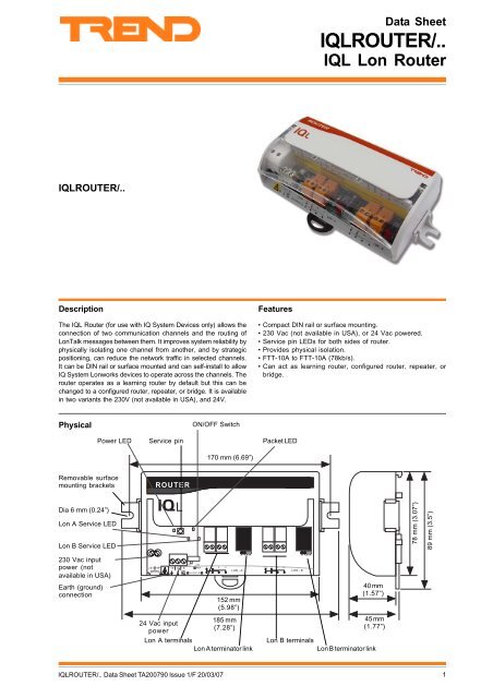
Physical<br />
ON/OFF Switch<br />
Power LED<br />
Service pin<br />
Packet LED<br />
170 mm (6.69”)<br />
Removable surface<br />
mounting brackets<br />
Dia 6 mm (0.24”)<br />
<strong>Lon</strong> A Service LED<br />
<strong>Lon</strong> B Service LED<br />
78 mm (3.07”)<br />
89 mm (3.5”)<br />
230 Vac input<br />
power (not<br />
available in USA)<br />
Earth (ground)<br />
connection<br />
. .<br />
2 ! " # 6<br />
! 8 ) +<br />
24 Vac input<br />
power<br />
" 8<br />
) 5 8 + *<br />
$ % & ' !<br />
)<br />
152 mm<br />
(5.98”)<br />
185 mm<br />
(7.28”)<br />
<strong>Lon</strong> A terminals<br />
<strong>Lon</strong> A terminator link<br />
*<br />
40 mm<br />
(1.57”)<br />
45 mm<br />
(1.77”)<br />
<strong>Lon</strong> B terminals<br />
<strong>Lon</strong> B terminator link<br />
<strong><strong>IQL</strong>ROUTER</strong>/.. <strong>Data</strong> <strong>Sheet</strong> TA200790 Issue 1/F 20/03/07<br />
1
<strong><strong>IQL</strong>ROUTER</strong>/..<br />
<strong>Data</strong> <strong>Sheet</strong><br />
FUNCTIONALITY<br />
The functionality of the <strong>IQL</strong> <strong>Router</strong> can be divided into two areas, System, and Hardware.<br />
SYSTEM<br />
The <strong>IQL</strong> <strong>Router</strong> consists of two neuron processors (one for each channel) back to back, with a transceiver either side.<br />
By default it is configured to be a learning router which allows<br />
a domain (IQ System) to span the router. It discards corrupt data<br />
and physically isolates one channel from another providing<br />
increased bus cable length and an increased number of nodes.<br />
If required the <strong>IQL</strong> router’s configuration can be changed using<br />
a <strong>Lon</strong>works network management tool to be a bridge, configured<br />
router, or repeater.<br />
Default Configuration<br />
The default configuration of the <strong>IQL</strong> <strong>Router</strong> is a learning router<br />
with the domain and message buffer length suitable for IQ<br />
System <strong>Lon</strong>works devices (domain 1=255, buffer length=146<br />
bytes). This ensures that when IQ System <strong>Lon</strong>works devices<br />
(e.g. <strong>IQL</strong>, LINC, and LERN) are installed either side of the <strong>IQL</strong><br />
<strong>Router</strong>, they will be able to communicate with each other.<br />
Subnets and hence IQ System Lans cannot cross routers. LINCs<br />
version >=3.23 can span routers, however earlier versions<br />
cannot without configuration using a <strong>Lon</strong>works network<br />
management tool. The IQ System internetwork can span a router<br />
as it is not limited to one subnet.<br />
Configuration by <strong>Lon</strong>works Management Tool<br />
In an IQ System-only <strong>Lon</strong>works solution, a <strong>Lon</strong>works network<br />
management tool is not required because the IQ System <strong>Lon</strong>Works<br />
products self-install a set of default network management<br />
parameters.<br />
The use of a <strong>Lon</strong>works network management tool enables IQ<br />
strategy modules to be bound to <strong>Lon</strong>Works devices (e.g.<br />
<strong>Lon</strong>works sensors or valves) or to allow LINCs pre-version 3.23<br />
to straddle a router.<br />
It can be used to change the router from its default as a learning<br />
router to be a bridge, a configured router, or a repeater.<br />
Note that a <strong>Lon</strong>works network management tool should only be<br />
used by an installer with <strong>Lon</strong>Works engineering expertise.<br />
Routing Algorithms<br />
Using a <strong>Lon</strong>works network management tool, the routing algorithm<br />
may be set to Bridge, <strong>Router</strong> (Learning or Configured), or Repeater.<br />
Note that all these devices will give physical isolation, increasing<br />
the length of wire that can be used (doubling it if the transmission<br />
medium stays the same), and increasing the number of nodes.<br />
Bridge: A bridge will forward all valid packets that match its<br />
domain address from one transceiver to the other. It thus bridges<br />
this domain and separates others.<br />
<strong>Router</strong>: A router will route <strong>Lon</strong>Talk messages according to its<br />
internal routing tables based on subnet and domain address. It<br />
allows network traffic to be reduced by filtering out local traffic<br />
from passing through the router. The learning router will learn<br />
which subnets are connected to either of its two transceivers<br />
and set up the routing tables accordingly. The configured router<br />
needs the actual distribution of the subnets to be configured into<br />
its routing tables using a <strong>Lon</strong>works network management tool.<br />
Note that a subnet cannot span a router.<br />
4 7 6 - 4<br />
) *<br />
6 H = I A EL A H A K H A K H 6 H = I A EL A H<br />
Transceiver<br />
The transmission medium both sides of the router is FTT-10A.<br />
This medium uses twisted pair cable with transformer coupling<br />
in each node to isolate the data bus from the transceivers. It<br />
supports free topology, so it may be wired as star, bus, or loop,<br />
or a mix of these, with a single terminator at one point.<br />
A description of FTT-10A is given in the ‘<strong>Lon</strong>Works FTT-10A Free<br />
Topology Transceiver User’s Guide (078-0156-01D)’.<br />
FTT-10A nodes may also be connected to a Link powered bus<br />
(LPT-10). In this type of medium, power is supplied to the bus by<br />
a Link Power Interface (LPI-10), and taken from the bus by the<br />
LPT-10 nodes, so these nodes do not have to be separately<br />
powered. The bus is normally grounded at the LPI-10, and the<br />
LPT-10 nodes must not be grounded. Since nodes often will have<br />
to control I/O which is grounded locally for functional or safety<br />
reasons, FTT-10A nodes which are separately powered and<br />
grounded are used. The distance constraints on an LPT-10 bus<br />
are different, see ‘LPT-10 Link Power Transceiver User’s Guide<br />
(078-0105-01C)’.<br />
Cable/Cable Length/Node to Node distance: The table below<br />
assumes maximum wire temperature of 55 °C (131 °F) (cable<br />
length is the total length of cable used including stubs - the short<br />
lengths of cable to junction boxes, if used).<br />
Recommended<br />
Number of Nodes: 64 nodes per segment maximum.<br />
Bus Termination: Each <strong>Lon</strong>works segment must be terminated<br />
at one point; this is facilitated by the <strong>IQL</strong> <strong>Router</strong>’s <strong>Lon</strong> terminator<br />
links.<br />
<strong>Lon</strong> A<br />
Cables<br />
Max bus length<br />
<strong><strong>IQL</strong>ROUTER</strong><br />
Integrated terminators<br />
Max node<br />
node<br />
500 m (545<br />
B elden 85102<br />
500<br />
m (545 yds)<br />
yds)<br />
<strong>Trend</strong><br />
TP/1/0/16/HF/200 500<br />
m (545 yds) 400 m (430 yds)<br />
(Belden 8471)<br />
U L Level IV, 22 AWG 500<br />
m (545 yds)<br />
400 m (430 yds)<br />
J Y(St) Y2 x 2 x 0.8 500<br />
m (545 yds)<br />
320 m (350 yds)<br />
T IA568A Cat. 5, 24 AWG 450<br />
m (490 yds)<br />
250 m (270 yds)<br />
to<br />
<strong>Lon</strong> B<br />
Repeater: The repeater passes all valid packets from one<br />
transceiver to the other.<br />
2 <strong><strong>IQL</strong>ROUTER</strong>/.. <strong>Data</strong> <strong>Sheet</strong> TA200790 Issue 1/F 20/03/07
<strong>Data</strong> <strong>Sheet</strong><br />
<strong><strong>IQL</strong>ROUTER</strong>/..<br />
HARDWARE<br />
Unit: The <strong>IQL</strong> <strong>Router</strong> is a small router designed for surface or<br />
DIN rail mounting. It has a plastic housing with a hinged clear<br />
polycarbonate terminal cover.<br />
Input Power: The 24V version requires 24Vac input power.<br />
The 230V version (not available in USA) requires 230 Vac +15%<br />
-10%, 50/60 Hz input power. Both versions have a consumption<br />
of 2 VA.<br />
!<br />
Note that the <strong><strong>IQL</strong>ROUTER</strong> must be earthed<br />
(grounded) using its input power connector earth<br />
(ground) terminal.<br />
The input power earth (ground) terminal is isolated from the input<br />
power neutral, and must be separately earthed (grounded) locally.<br />
Service Button: This is used if the router is to be installed using<br />
a <strong>Lon</strong>works network management tool. During the installation<br />
process, the tool will request to be informed of the presence of<br />
the router on a channel; this is done by pressing the Service<br />
button. This will be requested for each channel.<br />
<strong>Lon</strong>works: The integral <strong>Lon</strong>works transceiver uses FTT (or<br />
LPT) which has the following features:<br />
(1) Use of free bus topology enabling star, bus, or loop<br />
wiring simplifies installation and facilitates network<br />
expansion.<br />
(2) The bus uses two wires (twisted pair) which are polarity<br />
independent with no need for screen.<br />
(3) The FTT runs at 78 k baud.<br />
(4) The FTT <strong>Lon</strong>works may already be present in a building,<br />
so the IQ system is able to make use of an existing building<br />
bus and hence reduce installation cost.<br />
<strong>Lon</strong> Terminator Links: The <strong>Lon</strong> terminator links enable the<br />
<strong>Lon</strong>works network to be terminated. There is a separate link for<br />
each side of the router. Each can be set to one of two positions,<br />
OFF, or Free. When set to OFF there is no termination, and the<br />
network must be terminated elsewhere. When set to Free the<br />
network is terminated at that point with a 50 Ω termination.<br />
Connectors: Two part connectors for 0.5 to 2.55 mm 2 (14 to<br />
20 AWG) cross section area cable are used for the <strong>Lon</strong><br />
connections. Single part connectors for 0.5 to 2.55 mm 2 (14 to<br />
20 AWG) cross section area cable are used for both the 230 V<br />
and 24 V power connections.<br />
ON/OFF Switch: The ON/OFF is used to provide a power up<br />
reset to the unit. A reset may be required if the addressing of<br />
other IQ System devices on the network is changed.<br />
Indicators: The <strong>IQL</strong> <strong>Router</strong> has four LED indicators:<br />
Packet LED<br />
Power LED<br />
Service A LED<br />
Service B LED<br />
Flashes on when traffic is passing<br />
through the router.<br />
On when power is on<br />
Flashes on when the <strong>Lon</strong>works Network<br />
Management tool is requesting the<br />
Service button be pressed for side A of<br />
the router.<br />
Flashes on when the <strong>Lon</strong>works Network<br />
Management tool is requesting the<br />
Service button be pressed for side B of<br />
the router.<br />
DISPOSAL<br />
COSHH (Control of Substances Hazardous to Health - UK<br />
Government Regulations 2002) ASSESSMENT FOR DISPOSAL<br />
OF <strong>IQL</strong> ROUTER. No parts affected.<br />
RECYCLING.<br />
All plastic and metal parts are recyclable. The printed circuit<br />
board may be sent to any PCB recovery contractor to recover<br />
some of the components for any metals such as gold and silver.<br />
WEEE Directive :<br />
At the end of their useful life the packaging and<br />
product, should be disposed of by a suitable<br />
recycling centre.<br />
Do not dispose of with normal household waste.<br />
Do not burn.<br />
ORDER CODES<br />
Non USA Order Code USA Order Code<br />
<strong><strong>IQL</strong>ROUTER</strong>/230 Not available in USA <strong>IQL</strong> <strong>Router</strong> with 230 Vac power option (not available in USA).<br />
<strong><strong>IQL</strong>ROUTER</strong>/USA/UL24VAC 882001300 <strong>IQL</strong> <strong>Router</strong> 24 Vac UL Listed.<br />
INSTALLATION<br />
Both versions must be installed inside a protective case. The <strong><strong>IQL</strong>ROUTER</strong>/24VAC is UL rated as ‘UL916 listed open energy<br />
management equipment’. The unit can be mounted either on DIN rail or flat surface. The installation involves the following procedure:<br />
Mount the unit in position<br />
Connect input power (do not switch on)<br />
Earth (ground) unit<br />
Connect <strong>Lon</strong>Works network<br />
Switch on power to unit<br />
Set up with <strong>Lon</strong>works Management Tool if required<br />
Checking LEDs<br />
Configure rest of system<br />
Test system<br />
Note: If installation on a <strong>Lon</strong>works Management Tool is required, the installer must have <strong>Lon</strong>Works engineering expertise.<br />
<strong><strong>IQL</strong>ROUTER</strong>/.. <strong>Data</strong> <strong>Sheet</strong> TA200790 Issue 1/F 20/03/07<br />
3
! 8 ) +<br />
. . * 7 5 . 4 - - . . * 7 5 . 4 - -<br />
$ % & ' !<br />
<strong><strong>IQL</strong>ROUTER</strong>/..<br />
<strong>Data</strong> <strong>Sheet</strong><br />
CONNECTIONS<br />
<strong>Lon</strong>works Side A and Side B<br />
<strong>Lon</strong>works has free bus topology<br />
24 Vac Version<br />
WARNING: This apparatus must be earthed<br />
(grounded) using earth (ground) terminal.<br />
!<br />
24Vac<br />
" 8<br />
Earth (ground)<br />
24 Vac input<br />
power neutral at<br />
transformer<br />
<strong>Lon</strong> A<br />
<strong>Lon</strong> B<br />
<strong>Lon</strong>works<br />
Polarity independent<br />
LON<br />
4 5 6 7<br />
8 9 10 11<br />
*6 A H E = J H<br />
Terminator<br />
*<br />
6 A H E = J H<br />
*<br />
6 A H E = J H<br />
Do not allow<br />
<strong>Lon</strong>works<br />
wires to<br />
cross on a<br />
loop<br />
*Terminate <strong>Lon</strong>works bus at one point only. This<br />
can be done using the <strong>IQL</strong> <strong>Router</strong>’s <strong>Lon</strong>works<br />
terminator links, or a LONTERMINATOR .<br />
<strong>Lon</strong> A<br />
<strong>Lon</strong> B<br />
230 Vac Version (not available in USA)<br />
<br />
!<br />
! 8 = <br />
L<br />
N<br />
E<br />
WARNING: This apparatus must be earthed (grounded) using<br />
earth (ground) terminal.<br />
. .<br />
! " # 2 6<br />
" 8<br />
) 5 8 + *<br />
)<br />
*<br />
SPECIFICATIONS<br />
Electrical<br />
Input Power<br />
/230 (not USA) :230 Vac -10% +15%, 50/60 Hz<br />
/24 :18 to 30 Vac<br />
Consumption :2 VA<br />
Processor<br />
:2 Neuron 3150 chips (RTR10)<br />
Delay<br />
<strong>Lon</strong><br />
<strong>Lon</strong> FTT databus<br />
Recommended<br />
Cables<br />
:2.5 ms maximum<br />
:FTT - Free topology, 78 k baud,<br />
transformer isolated. Single termination<br />
(RC network).<br />
:Maximum bus length, node to node<br />
distance depends on cable type.<br />
Max bus length<br />
Max node<br />
node<br />
500 m (545<br />
B elden 85102<br />
500<br />
m (545 yds)<br />
yds)<br />
<strong>Trend</strong><br />
TP/1/0/16/HF/200 500<br />
m (545 yds) 400 m (430 yds)<br />
(Belden 8471)<br />
U L Level IV, 22 AWG 500<br />
m (545 yds)<br />
400 m (430 yds)<br />
J Y(St) Y2 x 2 x 0.8 500<br />
m (545 yds)<br />
320 m (350 yds)<br />
T IA568A Cat. 5, 24 AWG 450<br />
m (490 yds)<br />
250 m (270 yds)<br />
Version<br />
This data sheet refers to firmware v1.0, board LA105677 v1<br />
to<br />
Mechanical<br />
Dimensions :170mm (6.69”) x 89mm (3.5”) x 45 mm (1.77”)<br />
Material<br />
Box<br />
:Flame retardant ABS<br />
Terminal Cover :Clear polycarbonate flap<br />
Weight<br />
/230 (not USA):262g (9.94 oz)<br />
/24 :182g (6.42 oz)<br />
Connectors<br />
<strong>Lon</strong> :Two part connectors for 0.5 to 2.55 mm 2 (14<br />
to 20 AWG) cross section area cable.<br />
Power :Single part connectors for 0.5 to 2.55 mm 2 (14<br />
to 20 AWG) cross section area cable.<br />
Environmental<br />
EU<br />
EMC Emission<br />
EMC Immunity<br />
Safety<br />
USA/Canada<br />
Canada<br />
Ambient limits<br />
storage<br />
operating<br />
humidity<br />
:EN61000-6-3:2001, EN61000-3-2:2000,<br />
:EN61000-3-3:1995, EN61000-3-3:1995.<br />
:EN61010-1:2001<br />
:/24VAC only. UL rated as ‘UL916 listed open<br />
energy management equipment’.<br />
:CSA22.2 No. 205-M1983 - Signal Equipment.<br />
:-10 °C (+14 °F) to 50 °C (122 °F)<br />
:0 °C (32 °F) to +45 °C (113 °F)<br />
:0 to 95 %RH non-condensing<br />
Protection :IP20, NEMA1<br />
©Echelon Corporation. Echelon, LON, Neuron, LONWORKS are U.S. registered trademarks of Echelon Corporation. LONMARK is<br />
a trademark of Echelon Corporation.<br />
Manufactured for and on behalf of the Environmental and Combustion Controls Division of Honeywell Technologies Sàrl, Ecublens, Route<br />
du Bois 37,Switzerland by its Authorized Representative, <strong>Trend</strong> Control Systems Limited.<br />
<strong>Trend</strong> Control Systems Limited reserves the right to revise this publication from time to time and make changes to the content<br />
hereof without obligation to notify any person of such revisions or changes.<br />
<strong>Trend</strong> Control Systems Limited<br />
P.O. Box 34, Horsham, West Sussex, RH12 2YF, UK. Tel:+44 (0)1403 211888 Fax:+44 (0)1403 241608 www.trend-controls.com<br />
<strong>Trend</strong> Control Systems USA<br />
6670 185th Avenue NE, Redmond, Washington 98052, USA. Tel: (425)869-3900, Fax: (425)869-8445 www.trend-controls.com<br />
4 <strong><strong>IQL</strong>ROUTER</strong>/.. <strong>Data</strong> <strong>Sheet</strong> TA200790 Issue 1/F 20/03/07


