Design of Antennas for Handheld DVB-H ... - Lunds tekniska högskola
Design of Antennas for Handheld DVB-H ... - Lunds tekniska högskola
Design of Antennas for Handheld DVB-H ... - Lunds tekniska högskola

Create successful ePaper yourself
Turn your PDF publications into a flip-book with our unique Google optimized e-Paper software.
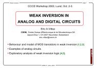
Figure 5.6. Radiation pattern <strong>for</strong> Reference antenna, frequency=560 MHz,<br />
Theta=0°-350°, Phi=90°, A=Phi polarization, B= Theta polarization.<br />
To determine the power gain <strong>for</strong> our antennas we must measure the radiated<br />
signal in the whole sphere. The maximum value <strong>of</strong> all these values is equivalent to<br />
2.15 dBi power gain <strong>for</strong> an ideal dipole, because our reference antennas are not<br />
ideal we estimated the maximum power gain to 1.6 dBi. Then the maximum<br />
absorbed signal <strong>for</strong> our antennas can be compared with this value <strong>for</strong> respective<br />
frequency (see equation 5.1).<br />
G=A-B+1.6 (5.1)<br />
G=Antenna power gain in dBi.<br />
A=Received signal strength in our prototype.<br />
B=Received signal strength in the reference antenna.<br />
To find out the efficiency <strong>for</strong> our antennas we must calculate TRP, total radiated<br />
power <strong>for</strong> both the reference antenna and our prototype.<br />
2π<br />
π<br />
⎧<br />
⎫<br />
Prad = B0<br />
∫ ⎨∫<br />
f ( θ ) ⋅ sin θ ⋅ dθ<br />
⎬dφ<br />
0 ⎩ 0<br />
⎭<br />
Numerical equation:<br />
(5.2)<br />
P<br />
rad<br />
⎛ π ⎞⎛<br />
2π<br />
⎞<br />
= B0⎜<br />
⎟⎜<br />
⎟<br />
⎝ N ⎠⎝<br />
M ⎠<br />
M<br />
⎡<br />
∑ ⎢∑<br />
⎣<br />
N<br />
j=<br />
1 i=<br />
1<br />
F(<br />
θ φ<br />
i,<br />
j<br />
) sin<br />
θ<br />
i<br />
⎤<br />
⎥<br />
⎦<br />
57<br />
(5.3)