Insulated - Siemens
Insulated - Siemens
Insulated - Siemens

You also want an ePaper? Increase the reach of your titles
YUMPU automatically turns print PDFs into web optimized ePapers that Google loves.
Fixed-Mounted Circuit-Breaker<br />
Switchgear Type NXPLUS<br />
up to 40.5 kV, SF 6 -<strong>Insulated</strong><br />
Medium-Voltage<br />
Switchgear<br />
Catalog HA 35.51<br />
2003<br />
Supersedes:<br />
Catalog HA 35.51 · 2001
R-HA35-085b eps<br />
R-HA35-086b eps<br />
Fixed-Mounted Circuit-Breaker Switchgear Type NXPLUS up to 40.5 kV, SF6-<strong>Insulated</strong><br />
Contents<br />
Application<br />
Page<br />
Application<br />
Types, typical uses 2 to 4<br />
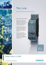
Types<br />
NXPLUS fixed-mounted circuit-breaker switchgear<br />
is a three-pole, metal-enclosed, metal-clad, SF 6 -insulated switchgear<br />
for indoor installation in single-busbar and double-busbar design.<br />
Requirements<br />
Features, safety, technology 4 and 5<br />
Technical Data<br />
Electrical data, dimensions 6<br />
Room planning 7<br />
Product Range<br />
Single-busbar panels 8 and 9<br />
Double-busbar panels 10 and 11<br />
Design<br />
Single-busbar panel design 12 and 13<br />
Double-busbar panel design 14 and 15<br />
Components<br />
Panel interconnection, module coupling 16<br />
Switching devices 17<br />
Protection, control, indicating<br />
and measuring equipment 18 and 19<br />
Mechanical control board 20<br />
Instrument transformers 21<br />
Panel connection 22 and 23<br />
Standards<br />
Standards, specifications, guidelines 24 to 26<br />
Notes<br />
27<br />
Single-busbar<br />
panel<br />
Double-busbar<br />
panel<br />
© <strong>Siemens</strong> AG 2003<br />
2 <strong>Siemens</strong> HA 35.51 · 2003<br />
Features<br />
• Environmental independence<br />
thanks to welded stainlesssteel<br />
switchgear vessel<br />
without seals<br />
• Compact design thanks to<br />
SF 6 -insulation<br />
• Maintenance-free design<br />
thanks to<br />
– Hermetically welded<br />
switchgear vessel<br />
– Maintenance-free switching<br />
devices<br />
• Innovations thanks to<br />
– Numerical substation control<br />
and protection systems<br />
– Combined protection and<br />
control systems
R-HA35-093a eps<br />
R-HA35-090 eps<br />
R-HA35-092 eps<br />
Fixed-Mounted Circuit-Breaker Switchgear Type NXPLUS up to 40.5 kV, SF6-<strong>Insulated</strong><br />
Application<br />
Typical uses<br />
Application<br />
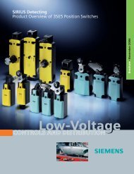
Public power supply system<br />
R-HA35-091 eps<br />
Application<br />
Offshore wind generators<br />
(photo: Vestas Denmark)<br />
NXPLUS switchgear<br />
with maximum equipment<br />
Application Steelworks<br />
<strong>Siemens</strong> HA 35.51 · 2003 3
Fixed-Mounted Circuit-Breaker Switchgear Type NXPLUS up to 40.5 kV, SF6-<strong>Insulated</strong><br />
Application<br />
Requirements<br />
Typical uses<br />
Fixed-mounted circuit-breaker switchgear<br />
NXPLUS is used in transformer<br />
and switching substations, e. g. in:<br />
■ Power supply companies<br />
■ Power stations<br />
■ Cement industry<br />
■ Automobile industry<br />
■ Iron and steelworks<br />
■ Rolling mills<br />
■ Mining industry<br />
■ Textile, paper and food industries<br />
■ Chemical industry<br />
■ Petroleum industry<br />
■ Pipeline installations<br />
■ Offshore installations<br />
■ Electrochemical plants<br />
■ Petrochemical plants<br />
■ Shipbuilding industry<br />
■ Diesel power plants<br />
■ Emergency power supply installations<br />
■ Lignite open-cast mines<br />
■ Traction power supply systems<br />
Features<br />
Environmental independence<br />
Welded switchgear vessels<br />
made of stainless steel without<br />
seals and enclosed cable plugs<br />
make NXPLUS switchgear<br />
• Insensitive to aggressive ambient<br />
conditions such as salt<br />
water, humidity, dust and<br />
temperature<br />
• Hermetically tight to ingress<br />
of foreign bodies such as dust<br />
and dirt<br />
• Independent of site altitude<br />
Compact design<br />
Thanks to the SF 6 -insulation,<br />
compact dimensions are<br />
possible up to 40.5 kV.<br />
Thus,<br />
• Existing switchgear rooms<br />
can be used effectively<br />
• Reduced costs for new<br />
constructions<br />
• Expensive city-area space is<br />
saved<br />
Maintenance-free design<br />
Switchgear vessels designed<br />
as sealed pressure systems,<br />
maintenance-free switching<br />
devices and enclosed cable<br />
plugs ensure<br />
• Maximized power supply<br />
reliability<br />
• Personal safety<br />
• Sealed-for-life design<br />
according to IEC 60 298<br />
• Installation, operation,<br />
extension and replacement<br />
without SF 6 -gas work<br />
• Reduced operating costs<br />
• Cost-efficient investment<br />
• No maintenance cycles<br />
• Reduced overall LCC<br />
(Life-Cycle Cost)<br />
Innovations<br />
The use of numerical<br />
substation control and<br />
protection systems and<br />
combined protection and<br />
control devices ensure<br />
• Clear integration in process<br />
control systems<br />
• Flexible and highly simplified<br />
adaptation to new<br />
system conditions and<br />
thus to cost-efficient<br />
operation<br />
4 <strong>Siemens</strong> HA 35.51 · 2003
Fixed-Mounted Circuit-Breaker Switchgear Type NXPLUS up to 40.5 kV, SF6-<strong>Insulated</strong><br />
Requirements<br />
Safety<br />
Technology<br />
Personal safety<br />
• Safe-to-touch and hermetically<br />
sealed primary enclosure<br />
• All high-voltage parts including<br />
the cable terminations,<br />
busbars and voltage transformers<br />
are surrounded by<br />
earthed layers or metal enclosures<br />
• Capacitive voltage detection<br />
system for verification of safe<br />
isolation from supply<br />
• Operating mechanisms and<br />
auxiliary switches safely accessible<br />
outside the primary<br />
enclosure (switchgear vessel)<br />
• Protective system interlock to<br />
prevent operation when the<br />
switchgear enclosure is open<br />
• Standard degree of protection<br />
IP 65 (primary part)<br />
and IP 3XD (secondary part)<br />
according to IEC 60 529 /<br />
VDE 0470 Part 1<br />
• High resistance to internal<br />
arcs by logical mechanical<br />
interlocks and tested switchgear<br />
enclosure<br />
• Arc-fault-tested panels<br />
according to IEC 60 298 /<br />
VDE 0670 Part 6<br />
• Logical mechanical and / or<br />
electrical interlocks prevent<br />
maloperation<br />
Operating safety<br />
• Hermetically sealed primary<br />
enclosure independent of<br />
environmental effects<br />
(dirt, moisture and small<br />
animals)<br />
• Maintenance-free in an<br />
indoor environment<br />
(IEC 60 694 / VDE 0670<br />
Part 1000)<br />
• Operating mechanisms of<br />
switching devices accessible<br />
outside the switchgear<br />
vessel (primary enclosure)<br />
• Metal-enclosed, plug-in inductive<br />
voltage transformers<br />
mounted outside the<br />
gas compartments<br />
• Ring-core current transformers<br />
mounted outside<br />
the gas compartments<br />
• Complete logical mechanical<br />
interlocking system<br />
• Welded switchgear vessels,<br />
sealed for life<br />
• Minimum fire load<br />
• Type and routine-tested<br />
• Standardized, NC production<br />
processes<br />
• Quality assurance<br />
in accordance with<br />
DIN EN ISO 9001<br />
• More than 300,000<br />
switchgear panels of<br />
<strong>Siemens</strong> in operation<br />
worldwide for many years<br />
• Successfully tested for use<br />
down to –20 °C<br />
• Option: Aseismic design<br />
General<br />
• Three-pole enclosure of the<br />
primary part consisting of a<br />
switchgear vessel made of<br />
stainless steel<br />
• Insulating gas SF 6<br />
• Three-position switch as<br />
busbar disconnector and<br />
feeder earthing switch<br />
• Make-proof earthing by<br />
means of the vacuum circuitbreaker<br />
• Outgoing and incoming<br />
feeder panel width: 600 mm<br />
• Hermetically welded switchgear<br />
vessel made of stainless<br />
steel without seals<br />
• Single-pole, solid-insulated,<br />
screened, bolted-type<br />
module coupling<br />
• Cable connection with inside<br />
or outside cone plug-in<br />
systems or connection of<br />
solid-insulated bars<br />
• Wall-standing or freestanding<br />
arrangement<br />
• Cable connection access from<br />
front or rear<br />
• Doors left or right-hinged<br />
• Existing switchgear extendable<br />
on both sides without<br />
modification of panels<br />
• Internal panel control cables<br />
laid in metallic cable ducts<br />
Modular design<br />
• Circuit-breaker module<br />
replacement possible<br />
without SF 6 -gas work and<br />
without interrupting<br />
busbar operation<br />
• Low-voltage compartment<br />
can be removed without<br />
interrupting the bus wires<br />
Instrument transformers<br />
• Can be removed without<br />
altering the positions of the<br />
busbar and circuit-breaker<br />
modules (outside the gas<br />
compartments)<br />
Vacuum circuit-breaker<br />
• Maintenance-free under<br />
normal ambient conditions<br />
according to IEC 60694 /<br />
VDE 0670 Part 1000<br />
• No relubrication or<br />
readjustment<br />
• Up to 10,000 operating<br />
cycles<br />
• Vacuum-tight for life<br />
Interlocks<br />
• According to IEC 60 298 /<br />
VDE 0670 Part 6<br />
• Electrical interlocks since<br />
all mechanisms are motor<br />
operating mechanisms<br />
• Manual emergency operating<br />
mechanisms with<br />
enabling key S1<br />
<strong>Siemens</strong> HA 35.51 · 2003<br />
5
Fixed-Mounted Circuit-Breaker Switchgear Type NXPLUS up to 40.5 kV, SF6-<strong>Insulated</strong><br />
Technical Data<br />
Electrical data<br />
Dimensions in mm<br />
Rated values<br />
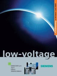
Single-busbar panels<br />
Single-busbar panels<br />
60<br />
1145 395<br />
Rated<br />
voltage<br />
max. kV<br />
7.2 12 24 36 40.5<br />
NX PLUS<br />
Rated<br />
frequency<br />
50 Hz 1 )<br />
1<br />
2<br />
280 280<br />
350<br />
935<br />
Rated short-duration powerfrequency<br />
withstand voltage<br />
kV<br />
20 28 50 70 85<br />
Rated lightning impulse<br />
withstand voltage<br />
kV<br />
60 75 125 170 185<br />
2450<br />
Rated short-circuit<br />
breaking current<br />
max. 31.5 kA<br />
1515<br />
Rated short-time<br />
withstand current, 3 s<br />
Rated short-circuit<br />
making current<br />
Rated peak<br />
withstand current<br />
Rated normal<br />
current of busbar<br />
max. A<br />
max. 31.5 kA<br />
max. 80 kA<br />
max. 80 kA<br />
2000<br />
2<br />
)<br />
2000<br />
2<br />
)<br />
2000<br />
2<br />
)<br />
2000<br />
2<br />
)<br />
2000<br />
80<br />
HA35-2427c eps<br />
B1<br />
Panel width B1<br />
Circuit-breaker panel<br />
Disconnector panel<br />
Bus sectionalizer panel<br />
1600<br />
1 End wall 2 Busbars<br />
600 mm<br />
600 mm<br />
900 mm<br />
Rated normal<br />
current of feeders<br />
max. A<br />
2000<br />
2<br />
)<br />
2000<br />
2<br />
)<br />
2000<br />
2<br />
)<br />
2000<br />
2<br />
)<br />
2000<br />
Double-busbar panels<br />
Double-busbar panels<br />
60<br />
1385 395<br />
Rated<br />
voltage<br />
max. kV<br />
7.2 12 24 36<br />
NX PLUS<br />
Rated<br />
frequency<br />
50 Hz 1 )<br />
1<br />
230<br />
2<br />
230<br />
230<br />
350<br />
935<br />
Rated short-duration powerfrequency<br />
withstand voltage<br />
kV<br />
20 28 50 70<br />
Rated lightning impulse<br />
withstand voltage<br />
kV<br />
60 75 125 170<br />
2600<br />
Rated short-circuit<br />
breaking current<br />
Rated short-time<br />
withstand current, 3 s<br />
Rated short-circuit<br />
making current<br />
max. 31.5 kA<br />
max. 31.5 kA<br />
max. 80 kA<br />
HA35-2428b eps<br />
1515<br />
Rated peak<br />
withstand current<br />
Rated normal<br />
current of busbar<br />
Rated normal<br />
current of feeders<br />
max. A<br />
max. A<br />
max. 80 kA<br />
2500 2500 2500 2500<br />
2500 2500 2500 2500<br />
80<br />
B2<br />
Panel width B2<br />
Circuit-breaker panel 3 )<br />
Bus coupler panel 3 )<br />
Bus sectionalizer panel,<br />
system 1 or system 2 4 )<br />
Metering panel<br />
1840<br />
1 End wall 2 Busbars<br />
600 mm<br />
600 mm<br />
600 mm<br />
300 mm<br />
1) 60 Hz on request<br />
2) 2500 A on request<br />
3) 1200 mm for 2300 / 2500 A<br />
4) 900 mm or 1200 mm for 2300 / 2500 A<br />
6 <strong>Siemens</strong> HA 35.51 · 2003
Fixed-Mounted Circuit-Breaker Switchgear Type NXPLUS up to 40.5 kV, SF6-<strong>Insulated</strong><br />
Technical Data<br />
Room planning<br />
Room planning for single-busbar See table on page 6 for dimension B1<br />
B1<br />
80<br />
80<br />
80<br />
80<br />
³50***<br />
³500**<br />
³50***<br />
³500**<br />
³50***<br />
³500**<br />
80<br />
80<br />
Single-row arrangement (top view)<br />
for single-busbar Face-to-face arrangement (top view)<br />
for single-busbar<br />
Room planning for double-busbar B2<br />
B2<br />
80<br />
80<br />
³50***<br />
³500**<br />
Single-row arrangement (top view)<br />
for double-busbar switchgear<br />
<br />
B2<br />
B2<br />
80<br />
80<br />
³50***<br />
³500**<br />
³50***<br />
³500**<br />
80<br />
80<br />
B2<br />
B2<br />
See table on page 6 for dimension B2<br />
Face-to-face arrangement (top view)<br />
for double-busbar switchgear<br />
* Aisle width<br />
** Free space next to last installed panel,<br />
either on left or right of switchgear row<br />
*** Recommended: W 500 mm<br />
<strong>Siemens</strong> HA 35.51 · 2003 7<br />
epsHA35-2407a ³1600* 1600 ³50<br />
<br />
³1600* 1840 ³250<br />
HA35-2408a eps<br />
HA35-2409a eps<br />
³50 1600<br />
³1600* 1600 ³50<br />
HA35-2410a eps<br />
³250 1840<br />
³1600* 1840 ³250
Fixed-Mounted Circuit-Breaker Switchgear Type NXPLUS up to 40.5 kV, SF6-<strong>Insulated</strong><br />
Product Range<br />
Single-busbar panels<br />
Circuit-breaker panel<br />
• With cable connection as<br />
inside cone for<br />
– Rated voltage up to 40.5 kV<br />
– Rated short-circuit breaking<br />
current up to 31.5 kA<br />
– Rated normal currents<br />
of busbars and feeders<br />
up to 2000 A<br />
(2500 A on request)<br />
• With cable connection as<br />
outside cone for<br />
– Rated voltage up to 24 kV<br />
– Rated short-circuit breaking<br />
current up to 25 kA<br />
(up to 12 kV: 31.5 kA)<br />
– Rated normal currents of<br />
busbars up to 2000 A<br />
(2500 A on request) and<br />
feeders up to 1250 A<br />
Disconnector panel<br />
• With cable connection as<br />
inside cone for<br />
– Rated voltage up to 40.5 kV<br />
– Rated short-time withstand<br />
current up to 31.5 kA<br />
– Rated normal currents<br />
of busbars and feeders<br />
up to 2000 A<br />
(2500 A on request)<br />
• With cable connection as<br />
outside cone for<br />
– Rated voltage up to 24 kV<br />
– Rated short-circuit breaking<br />
current up to 25 kA<br />
(up to 12 kV: 31.5 kA)<br />
– Rated normal currents of<br />
busbars up to 2000 A<br />
(2500 A on request) and<br />
feeders up to 1250 A<br />
Bus sectionalizer<br />
for<br />
– Rated voltage up to 40.5 kV<br />
– Rated short-circuit breaking<br />
current up to 31.5 kA<br />
– Rated normal current<br />
of busbars up to 2000 A<br />
(2500 A on request)<br />
HA35-2387b eps HA35-2386b eps<br />
Circuit-breaker panel (cable connection as inside cone)<br />
or<br />
or<br />
or<br />
and<br />
2 )<br />
Voltage<br />
transformer,<br />
plug-in type<br />
Surge<br />
arrester,<br />
plug-in type<br />
Busbar<br />
current<br />
transformer<br />
or<br />
or<br />
or<br />
or<br />
1 x plug-in<br />
cable,<br />
interface<br />
type2or3<br />
2 x plug-in<br />
cable,<br />
interface<br />
type2or3<br />
3 x plug-in<br />
cable,<br />
interface<br />
type2or3<br />
4 x plug-in<br />
cable,<br />
interface<br />
type 2<br />
Solidinsulated<br />
bar<br />
Surge<br />
arrester,<br />
plug-in type<br />
Circuit-breaker panel (cable connection as outside cone)<br />
or<br />
or<br />
or<br />
and<br />
2 )<br />
Capacitive<br />
voltage<br />
detection<br />
system<br />
1 x plug-in<br />
cable,<br />
interface<br />
type 2<br />
Capacitive<br />
voltage<br />
detection<br />
system<br />
1 x plug-in<br />
cable,<br />
interface<br />
type 2<br />
Voltage<br />
transformer,<br />
plug-in type<br />
Surge<br />
arrester,<br />
plug-in type<br />
Busbar<br />
current<br />
transformer<br />
or<br />
or<br />
Busbar components<br />
Panel connection<br />
versions<br />
Busbar components<br />
Panel connection<br />
versions<br />
1) Capacitive<br />
voltage<br />
detection<br />
system<br />
1 )<br />
1 )<br />
3 x plug-in<br />
cable<br />
2 x plug-in<br />
cable<br />
1 x plug-in<br />
cable<br />
Voltage<br />
transformer,<br />
plug-in type<br />
Voltage<br />
transformer,<br />
disconnectable<br />
Surge arrester<br />
or limiter,<br />
to be plugged in<br />
additionally<br />
2) Not possible<br />
with busbar<br />
voltage<br />
transformer<br />
Components<br />
before circuit-breaker module<br />
Components<br />
after circuit-breaker module 3 )<br />
Panel connection<br />
components<br />
Current<br />
transformer<br />
Components<br />
before circuit-breaker module<br />
Components<br />
after circuit-breaker module<br />
Panel connection<br />
components<br />
Current<br />
transformer<br />
3) Requires cable<br />
connection with<br />
vessel for separate<br />
inside cone<br />
8 <strong>Siemens</strong> HA 35.51 · 2003
Fixed-Mounted Circuit-Breaker Switchgear Type NXPLUS up to 40.5 kV, SF6-<strong>Insulated</strong><br />
Product Range<br />
Single-busbar panels<br />
Disconnector panel (cable connection as inside cone)<br />
Bus sectionalizer<br />
Busbar components<br />
Busbar<br />
components<br />
Components<br />
before bus riser module<br />
Components<br />
before circuitbreaker<br />
module<br />
Panel connection<br />
versions<br />
1 )<br />
Panel connection<br />
components<br />
or<br />
Capacitive<br />
voltage<br />
detection<br />
system<br />
1 x plug-in<br />
cable,<br />
interface<br />
type 2<br />
or<br />
1 x plug-in<br />
cable,<br />
interface<br />
type2or3<br />
2 x plug-in<br />
cable,<br />
interface<br />
type2or3<br />
Voltage<br />
transformer,<br />
plug-in type<br />
Current<br />
transformer<br />
HA35-2390b eps<br />
Capacitive<br />
voltage<br />
detection<br />
system<br />
Current<br />
transformer<br />
or<br />
Voltage<br />
transformer,<br />
plug-in type<br />
or<br />
3 x plug-in<br />
cable,<br />
interface<br />
type2or3<br />
or<br />
Surge<br />
arrester,<br />
plug-in type<br />
or<br />
4 x plug-in<br />
cable,<br />
interface<br />
type 2<br />
HA35-2388b eps<br />
and<br />
2 )<br />
Busbar<br />
current<br />
transformer<br />
or<br />
Solidinsulated<br />
bar<br />
Surge<br />
arrester,<br />
plug-in type<br />
Disconnector panel (cable connection as outside cone)<br />
Busbar components<br />
Panel connection<br />
versions<br />
1 )<br />
Components<br />
before cable connection module<br />
Components<br />
after bus riser module<br />
Panel connection<br />
components<br />
Capacitive<br />
voltage<br />
detection<br />
system<br />
3 x plug-in<br />
cable<br />
Voltage<br />
transformer,<br />
disconnectable<br />
Current<br />
transformer<br />
or<br />
1 x plug-in<br />
cable,<br />
interface<br />
type 2<br />
or<br />
2 x plug-in<br />
cable<br />
or<br />
Voltage<br />
transformer,<br />
plug-in type<br />
or<br />
1 x plug-in<br />
cable<br />
HA35-2389c eps<br />
or<br />
and<br />
2 )<br />
Surge<br />
arrester,<br />
plug-in type<br />
Busbar<br />
current<br />
transformer<br />
1) Capacitive<br />
voltage<br />
detection<br />
system<br />
Surge arrester<br />
or limiter,<br />
to be plugged in<br />
additionally<br />
2) Not possible<br />
with busbar<br />
voltage<br />
transformer<br />
<strong>Siemens</strong> HA 35.51 · 2003<br />
9
Fixed-Mounted Circuit-Breaker Switchgear Type NXPLUS up to 40.5 kV, SF6-<strong>Insulated</strong><br />
Product Range<br />
Double-busbar panels<br />
Circuit-breaker panel<br />
• With cable connection as<br />
inside cone for<br />
– Rated voltage up to 36 kV<br />
– Rated short-circuit breaking<br />
current up to 31.5 kA<br />
– Rated normal currents<br />
of busbars and feeders<br />
up to 2500 A<br />
• With cable connection as<br />
outside cone for<br />
– Rated voltage up to 24 kV<br />
– Rated short-circuit breaking<br />
current up to 25 kA<br />
(up to 12 kV: 31.5 kA)<br />
– Rated normal currents of<br />
busbars up to 2500 A and<br />
feeders up to 1250 A<br />
Bus sectionalizer<br />
(circuit-breaker panel and riser<br />
panel)<br />
• With cable connection as<br />
inside cone for<br />
– Rated voltage up to 36 kV<br />
– Rated short-circuit breaking<br />
current up to 31.5 kA<br />
– Rated normal currents of<br />
busbars and feeders<br />
up to 2500 A<br />
Bus sectionalizer<br />
for<br />
– Rated voltage up to 36 kV<br />
– Rated short-circuit breaking<br />
current up to 31.5 kA<br />
– Rated normal current<br />
of busbars up to 2500 A<br />
Bus coupler<br />
for<br />
– Rated voltage up to 36 kV<br />
– Rated short-circuit breaking<br />
current up to 31.5 kA<br />
– Rated normal current of<br />
busbars up to 2500 A<br />
HA35-2391c eps<br />
Circuit-breaker panel (cable connection as inside cone)<br />
Busbar<br />
current<br />
transformer<br />
Busbar components<br />
or<br />
or<br />
or<br />
or<br />
SS1<br />
SS2<br />
Panel connection<br />
versions<br />
1 )<br />
1 x plug-in<br />
cable,<br />
interface<br />
type2or3<br />
2 x plug-in<br />
cable,<br />
interface<br />
type2or3<br />
3 x plug-in<br />
cable,<br />
interface<br />
type2or3<br />
4 x plug-in<br />
cable,<br />
interface<br />
type 2<br />
Solidinsulated<br />
bar<br />
(e.g. Duresca<br />
bar)<br />
Voltage<br />
transformer,<br />
plug-in type<br />
Surge<br />
arrester,<br />
plug-in type<br />
Circuit-breaker panel (cable connection as outside cone)<br />
Busbar components<br />
SS1<br />
SS2<br />
1 )<br />
Components<br />
before circuit-breaker module<br />
Components<br />
after circuit-breaker module 2 )<br />
Panel connection<br />
components<br />
Current<br />
transformer<br />
Components<br />
after circuit-breaker module<br />
Panel connection<br />
components<br />
Current<br />
transformer<br />
3 )<br />
Metering panel<br />
for<br />
– Rated voltage up to 36 kV<br />
– Rated normal current of<br />
busbars up to 2500 A<br />
HA35-2392c eps<br />
Busbar<br />
current<br />
transformer<br />
or<br />
3 x plug-in<br />
cable<br />
2 x plug-in<br />
cable<br />
Voltage<br />
transformer,<br />
disconnectable<br />
Current<br />
transformer<br />
or<br />
1 x plug-in<br />
cable<br />
Surge arrester<br />
or limiter,<br />
to be plugged in<br />
additionally<br />
Abbreviations<br />
SS1 = Busbar 1<br />
SS2 = Busbar 2<br />
1) Capacitive voltage<br />
detection system<br />
2) Switchgear vessel for separate inside<br />
cone required for cable connection with<br />
2 to 4 cables per phase<br />
3) Ring-core current transformer,<br />
oval design, suitable for<br />
use from 1000 A up<br />
10 <strong>Siemens</strong> HA 35.51 · 2003
Fixed-Mounted Circuit-Breaker Switchgear Type NXPLUS up to 40.5 kV, SF6-<strong>Insulated</strong><br />
Product Range<br />
Double-busbar panels<br />
SS1<br />
SS2<br />
Bus sectionalizer (cable connection as inside cone)<br />
Bus sectionalizer, circuit-breaker panel<br />
Components<br />
before circuit-breaker module<br />
Bus sectionalizer, bus riser panel<br />
Components<br />
before bus riser module<br />
1 ) 1 ) Panel connection<br />
1 )<br />
components<br />
1 )<br />
Panel connection<br />
components<br />
Panel<br />
connection<br />
versions<br />
Voltage<br />
transformer,<br />
plug-in type<br />
Current<br />
transformer<br />
Panel<br />
connection<br />
versions<br />
Voltage<br />
transformer,<br />
plug-in type<br />
Current<br />
transformer<br />
1 x plug-in<br />
cable,<br />
interface<br />
type2or3<br />
1 x plug-in<br />
cable,<br />
interface<br />
type2or3<br />
or<br />
2 x plug-in<br />
cable,<br />
interface<br />
type2or3<br />
or<br />
2 x plug-in<br />
cable,<br />
interface<br />
type2or3<br />
or<br />
3 x plug-in<br />
cable,<br />
interface<br />
type2or3<br />
or<br />
3 x plug-in<br />
cable,<br />
interface<br />
type2or3<br />
or<br />
4 x plug-in<br />
cable,<br />
interface<br />
type 2<br />
or<br />
4 x plug-in<br />
cable,<br />
interface<br />
type 2<br />
HA35-2393b eps<br />
or<br />
Solidinsulated<br />
bar<br />
Surge<br />
arrester,<br />
plug-in type<br />
or<br />
Solidinsulated<br />
bar<br />
Surge<br />
arrester,<br />
plug-in type<br />
Bus sectionalizer<br />
Bus coupler<br />
Metering panel<br />
SS1<br />
SS2<br />
Components before<br />
circuit-breaker<br />
module<br />
SS1<br />
SS2<br />
Components before<br />
circuit-breaker<br />
module<br />
SS1<br />
SS2<br />
HA35-2394c eps<br />
HA35-2395b eps<br />
HA35-2396a eps<br />
Current<br />
transformer<br />
Current<br />
transformer<br />
1) Capacitive voltage<br />
detection system<br />
<strong>Siemens</strong> HA 35.51 · 2003<br />
11
Fixed-Mounted Circuit-Breaker Switchgear Type NXPLUS up to 40.5 kV, SF6-<strong>Insulated</strong><br />
Design<br />
Single-busbar panel design<br />
Features<br />
• Stainless-steel module of<br />
circuit-breaker and busbar<br />
• Sendzimir-galvanized sheetsteel<br />
enclosure<br />
• Self-supporting structure<br />
• Electrical connections via<br />
cast-resin insulated, screened<br />
and bolted module couplings<br />
• Low-voltage compartment<br />
can be removed without<br />
interrupting the bus wires<br />
• Degree of protection<br />
– IP 65 for primary parts<br />
– IP 3XD for secondary parts<br />
• Lateral metallic cable ducts<br />
for control cables<br />
• Suitable for connecting<br />
single and three-core cables<br />
as well as bars<br />
• Circuit-breaker module replacement<br />
without gas work<br />
and without interrupting<br />
busbar operation<br />
• Instrument transformers can<br />
be removed without changing<br />
the positions of busbar<br />
and circuit-breaker modules<br />
• Instrument transformers can<br />
be removed without gas work<br />
(located outside the gas compartments)<br />
• Maintenance-free vacuum<br />
circuit-breaker under normal<br />
ambient conditions according<br />
to IEC 60694 / VDE 0670,<br />
Part 1000<br />
• Option: plug-in busbar<br />
voltage transformer<br />
1<br />
2<br />
3<br />
4<br />
5<br />
6<br />
HA35-2397c eps<br />
7<br />
NX PLUS<br />
1 Door of low-voltage compartment<br />
2 Mimic diagram<br />
3 Multifunction protection relay<br />
SIPROTEC 4 type 7SJ61/ 7SJ62<br />
for protection and control<br />
4 EMERGENCY-OFF pushbutton,<br />
mechanical<br />
5 Door to mechanical control board<br />
6 Cover of connection compartment<br />
7 Busbar cover and space for plug-in<br />
busbar voltage transformer<br />
8 Busbar module, welded,<br />
SF 6 -insulated<br />
9 Rupture diaphragm<br />
10 Three-pole busbar system<br />
11 Three-position disconnector,<br />
SF 6 -insulated, with the three switch<br />
positions:<br />
CLOSED – OPEN – READY-TO-EARTH<br />
12 Module coupling between busbar<br />
module and circuit-breaker module<br />
13 Circuit-breaker module, welded,<br />
SF 6 -insulated, with integrated cable<br />
connection<br />
14 Vacuum interrupter of circuit-breaker<br />
15 Pressure relief duct<br />
16 Integrated cable connection as<br />
inside cone<br />
17 Low-voltage compartment,<br />
standard: 935 mm high,<br />
option: 1100 mm high<br />
18 Ring-core current transformer<br />
19 Manual and motor operating<br />
mechanism of three-position<br />
disconnector<br />
20 Mechanical control board<br />
21 Manual and motor operating<br />
mechanism of circuit-breaker<br />
8<br />
9<br />
10<br />
11<br />
12<br />
13<br />
14<br />
9<br />
15<br />
16<br />
9<br />
25<br />
18<br />
26<br />
9<br />
27<br />
9<br />
13<br />
18<br />
28<br />
29 23<br />
24<br />
Panel with integrated inside cone<br />
Panel with separate inside cone<br />
Panel with outside cone<br />
22 Voltage transformer connection socket as inside cone<br />
23 Cable connection compartment<br />
24 Voltage transformer<br />
25 Module coupling between circuit-breaker and<br />
cable connection module<br />
26 Cable connection module, welded, SF 6 -insulated,<br />
with separate cable connection<br />
27 Separate cable connection as inside cone<br />
28 Voltage transformer connection socket as outside cone<br />
29 Cable connection as outside cone<br />
17<br />
18<br />
19<br />
20<br />
21<br />
22<br />
23<br />
24<br />
24<br />
22<br />
12 <strong>Siemens</strong> HA 35.51 · 2003
Fixed-Mounted Circuit-Breaker Switchgear Type NXPLUS up to 40.5 kV, SF6-<strong>Insulated</strong><br />
Design<br />
Single-busbar panel design<br />
Modular design<br />
30<br />
30 Busbar module with three-position disconnector<br />
31 Module couplings between busbar module and<br />
circuit-breaker module<br />
32 Ring-core current transformer<br />
33 Circuit-breaker module with connection for inside<br />
cone plug-in system<br />
34 Voltage transformer, can be plugged in via cable<br />
35 Mechanical control board<br />
36 Multifunction protection relay SIPROTEC 4<br />
31<br />
32<br />
HA35-2425d eps<br />
33<br />
36<br />
35<br />
34<br />
<strong>Siemens</strong> HA 35.51 · 2003<br />
13
Fixed-Mounted Circuit-Breaker Switchgear Type NXPLUS up to 40.5 kV, SF6-<strong>Insulated</strong><br />
Design<br />
Double-busbar panel design<br />
Features<br />
• Stainless-steel module of<br />
circuit-breaker and busbar<br />
• Sendzimir-galvanized sheetsteel<br />
enclosure<br />
• Self-supporting structure<br />
• Electrical connections via<br />
cast-resin insulated, screened<br />
and bolted module couplings<br />
• Low-voltage compartment<br />
can be removed without<br />
interrupting the bus wires<br />
• Degree of protection<br />
– IP 65 for primary parts<br />
– IP 3XD for secondary parts<br />
• Lateral metallic cable ducts<br />
for control cables<br />
• Suitable for connecting<br />
single and three-core cables<br />
as well as bars<br />
• Circuit-breaker module replacement<br />
without gas work<br />
and without interrupting<br />
busbar operation<br />
• Instrument transformers can<br />
be removed without changing<br />
the positions of busbar<br />
and circuit-breaker modules<br />
• Instrument transformers can<br />
be removed without gas work<br />
(located outside the gas compartments)<br />
• Maintenance-free vacuum<br />
circuit-breaker under normal<br />
ambient conditions according<br />
to IEC 60694 / VDE 0670,<br />
Part 1000<br />
1<br />
2<br />
3<br />
4<br />
5<br />
6<br />
NX PLUS<br />
HA35-2401b eps<br />
1 Door of low-voltage compartment<br />
2 Mimic diagram<br />
3 Multifunction protection relay<br />
SIPROTEC 4 type 7SJ61/ 7SJ62<br />
for protection and control<br />
4 EMERGENCY-OFF pushbutton,<br />
mechanical<br />
5 Door to mechanical control board<br />
6 Cover of connection compartment<br />
7 Busbar cover<br />
8 Busbar module (2x), welded,<br />
SF 6 -insulated<br />
9 Rupture diaphragm<br />
10 Three-pole busbar system (2x)<br />
11 Three-position disconnector,<br />
SF 6 -insulated, with the three switch<br />
positions:<br />
CLOSED – OPEN – READY-TO-EARTH<br />
12 Module coupling between busbar<br />
module and circuit-breaker module<br />
13 Circuit-breaker module, welded,<br />
SF 6 -insulated, with integrated cable<br />
connection<br />
14 Vacuum interrupter of circuit-breaker<br />
15 Pressure relief duct<br />
16 Integrated cable connection as<br />
inside cone<br />
17 Low-voltage compartment,<br />
standard: 935 mm high,<br />
option: 1100 mm high<br />
18 Ring-core current transformer,<br />
normal or oval design<br />
19 Manual and motor operating<br />
mechanism of three-position<br />
disconnector<br />
7<br />
8<br />
10<br />
9<br />
11<br />
12<br />
13<br />
14<br />
9<br />
15<br />
16<br />
9<br />
25<br />
31<br />
26<br />
9<br />
27<br />
9<br />
13<br />
31<br />
28<br />
29 23<br />
9<br />
13<br />
16<br />
31<br />
30<br />
Panel with integrated inside cone<br />
Panel with separate inside cone<br />
Panel with outside cone<br />
Panel with integrated inside cone and current<br />
transformers in the cable connection compartment<br />
17<br />
18<br />
19<br />
20<br />
21<br />
22<br />
23<br />
24<br />
24<br />
22<br />
24<br />
22<br />
23<br />
24<br />
14 <strong>Siemens</strong> HA 35.51 · 2003
Fixed-Mounted Circuit-Breaker Switchgear Type NXPLUS up to 40.5 kV, SF6-<strong>Insulated</strong><br />
Design<br />
Double-busbar panel design<br />
Modular design (example)<br />
32<br />
33<br />
32 Busbar module for SS1<br />
with three-position disconnector<br />
33 Busbar module for SS2<br />
with three-position disconnector<br />
34 Module couplings between busbar module SS1<br />
and circuit-breaker module<br />
35 Module couplings between busbar module SS2<br />
and circuit-breaker module<br />
36 Ring-core current transformer, oval design<br />
37 Circuit-breaker module with connection<br />
for inside cone plug-in system<br />
38 Voltage transformer, can be plugged in via cable<br />
39 Mechanical control board<br />
40 Multifunction protection relay SIPROTEC 4<br />
34 35<br />
36<br />
HA35-2426d eps<br />
37<br />
40<br />
39<br />
38<br />
Continuation of the legend from page 14<br />
20 Mechanical control board<br />
21 Manual and motor operating<br />
mechanism of circuit-breaker<br />
22 Voltage transformer connection<br />
socket as inside cone<br />
23 Cable connection compartment<br />
24 Voltage transformer<br />
25 Module coupling between<br />
circuit-breaker module and<br />
cable connection module<br />
26 Cable connection module,<br />
welded, SF 6 -insulated, with<br />
separate cable connection<br />
27 Separate cable connection as<br />
inside cone<br />
28 Voltage transformer connection<br />
socket as outside cone<br />
29 Cable connection as outside cone<br />
30 Connection cables<br />
31 Ring-core current transformer<br />
Abbreviations<br />
SS1 = Busbar 1<br />
SS2 = Busbar 2<br />
<strong>Siemens</strong> HA 35.51 · 2003<br />
15
R-HA35-074 eps<br />
Fixed-Mounted Circuit-Breaker Switchgear Type NXPLUS up to 40.5 kV, SF6-<strong>Insulated</strong><br />
Components<br />
Panel interconnection, module coupling<br />
Panel interconnection<br />
• Designed with a module<br />
coupling<br />
• Solid-insulated<br />
• Connects the panels with<br />
each other, as well as the<br />
vessels within a panel<br />
Module coupling<br />
• Single-pole, bolted-type<br />
• Consisting of round copper<br />
with cast-resin insulation<br />
• Bolted busbar joint with<br />
silicone rubber insulation<br />
• Field control by means of<br />
electrically conductive layers<br />
of insulation (inside and<br />
outside)<br />
• Screened by earthing outer<br />
layers with switchgear vessel<br />
• Switchgear installation,<br />
extension or panel replacement<br />
without SF 6 -gas work<br />
1<br />
2<br />
3<br />
4<br />
5<br />
Panel interconnections<br />
in the circuit-breaker panel (example)<br />
6<br />
3<br />
1<br />
1 6<br />
2<br />
3<br />
3<br />
4<br />
1<br />
5<br />
Module couplings<br />
for single-busbar panels<br />
HA35-2375i eps<br />
Module couplings<br />
for double-busbar panels<br />
HA35-2411b eps<br />
Module coupling<br />
1 Module coupling<br />
2 Busbar module<br />
3 Current transformer<br />
4 Circuit-breaker module<br />
5 End wall<br />
6 Bushing in adjacent panel<br />
7<br />
8<br />
9<br />
10<br />
11<br />
7 Busbar conductor<br />
8 Silicone sleeve<br />
9 Earthing clamps<br />
10 High-quality joint<br />
11 Cast-resin bushing<br />
12 Vessel wall<br />
13 Cast-resin insulation<br />
14 Conductive layer<br />
15 Bolted busbar joint<br />
16 Pressure ring<br />
16<br />
Busbar module,<br />
SF 6 -insulated<br />
15<br />
14<br />
13<br />
Module coupling<br />
(solid-insulated)<br />
12<br />
HA35-2376e eps<br />
Busbar module,<br />
SF 6 -insulated<br />
16 <strong>Siemens</strong> HA 35.51 · 2003
Fixed-Mounted Circuit-Breaker Switchgear Type NXPLUS up to 40.5 kV, SF6-<strong>Insulated</strong><br />
Components<br />
Switching devices<br />
Vacuum circuit-breaker<br />
• Three-pole design<br />
• With maintenance-free vacuum<br />
interrupters (= primary<br />
part of the circuit-breaker)<br />
in the SF 6 -filled switchgear<br />
vessel<br />
• Force transmission from the<br />
operating mechanism to the<br />
circuit-breaker poles by means<br />
of rods in the switchgear<br />
vessel<br />
• Metal bellows, as already used<br />
with success a million times<br />
for vacuum interrupters, for<br />
gasketless separation of the<br />
SF 6 -insulation and the operating<br />
mechanism<br />
Operating mechanism<br />
• Located outside the gas compartments<br />
and behind the<br />
panel front<br />
• Low-lubricant level thanks to<br />
appropriate material combinations<br />
• Lubricants with anti-seizure<br />
properties and long endurance<br />
• Generally with manual and<br />
motor operating mechanism<br />
• Maintenance-free under normal<br />
ambient conditions (in<br />
the switchgear room) and<br />
with maximum permissible<br />
number of operating cycles:<br />
Mechanical<br />
10000 x<br />
R-HA35-073 eps R-HA35-072 eps<br />
Switching devices<br />
Vacuum circuit-breaker<br />
(operating mechanism side open)<br />
3<br />
1<br />
4<br />
2<br />
1 Vacuum interrupters in<br />
SF 6 -gas<br />
2 Operating mechanism<br />
box<br />
3 Three-position<br />
disconnector<br />
4 Operating mechanism<br />
At rated normal<br />
current<br />
10000 x<br />
At short-circuit<br />
breaking current<br />
50 x<br />
Three-position disconnector<br />
• Up to 2000 operating cycles<br />
• Compact design thanks to<br />
short contact gaps in SF 6 -gas<br />
• Operating shaft and contact<br />
blade with common pivot<br />
point and reliable switch<br />
position up to the panel<br />
operating front<br />
• Maintenance-free<br />
Operating mechanism<br />
• Switch position indication via<br />
mechanically coupled flag indicators<br />
• Separate operating shafts for<br />
the “Disconnecting” and<br />
“Ready-to-earth” functions<br />
• Generally with manual and<br />
motor operating mechanism<br />
Three-position disconnector<br />
with operating mechanism<br />
Switch positions of the three-position disconnector<br />
“CLOSED”<br />
• Closed current path<br />
between busbar and<br />
vacuum circuit-breaker<br />
• Contact blades connected<br />
with fixed contacts at the<br />
busbar bushings<br />
“OPEN”<br />
• Open current path<br />
between busbar and<br />
vacuum circuit-breaker<br />
• Isolating distances<br />
withstand prescribed test<br />
voltages<br />
“READY-TO-EARTH”<br />
• Contact blades connected<br />
with earthing contact of<br />
switchgear vessel<br />
• Earthing and short-circuiting<br />
of the cable connection<br />
possible by closing the<br />
vacuum circuit-breaker<br />
<strong>Siemens</strong> HA 35.51 · 2003<br />
17
Fixed-Mounted Circuit-Breaker Switchgear Type NXPLUS up to 40.5 kV, SF6-<strong>Insulated</strong><br />
Components<br />
Protection, control, indicating and measuring equipment (examples)<br />
• Operating mechanisms for<br />
three-position disconnectors<br />
and circuit-breakers<br />
• Electrical interlocks, optionally<br />
mechanical interlocks for<br />
single busbar<br />
• Conventional control<br />
system or via multifunction<br />
protection relays<br />
Multifunction protection relay<br />
SIPROTEC 4 7SJ600/7SJ602<br />
• User-friendly operating program<br />
DIGSI 4 for configuration<br />
and analysis<br />
• Communications and bus<br />
capability<br />
• Functions: control, protection,<br />
indicating, communications<br />
and measuring<br />
• LCD (2 text lines) and keyboard<br />
for local operation,<br />
configuration and display<br />
• Four user-programmable<br />
LEDs for displaying any<br />
desired data<br />
• Operation and fault indication<br />
memory<br />
• Fault recording<br />
• Circuit-breaker control<br />
Multifunction protection<br />
relay SIPROTEC 4 7SJ61/7SJ62<br />
• For stand-alone or master<br />
operation<br />
• Communications and bus<br />
capability<br />
• Functions: control, protection,<br />
indicating, communications<br />
and measuring<br />
• LCD (4 text lines) for process<br />
and equipment data, in the<br />
form of a feeder mimic diagram<br />
and as text, e.g. for<br />
– Measuring and metering<br />
values<br />
– Information on status of<br />
switchgear and switching<br />
device<br />
– Protection data<br />
– General indications<br />
– Alarms<br />
• Four user-programmable<br />
function keys for frequently<br />
performed actions<br />
• Seven user-programmable<br />
LEDs for displaying any<br />
desired data<br />
• Keys for navigation in menus<br />
and for entering values<br />
18 <strong>Siemens</strong> HA 35.51 · 2003<br />
Multifunction<br />
protection relay<br />
SIPROTEC 4 7SJ63<br />
• For stand-alone or<br />
master operation<br />
• Communications and<br />
bus capability<br />
• Functions: control,<br />
protection, indicating,<br />
communications<br />
and measuring<br />
• LCD for process and<br />
equipment data, in<br />
the form of a feeder<br />
mimic diagram and<br />
as text, e.g. for<br />
– Measuring and<br />
metering values<br />
– Information on status<br />
of switchgear and<br />
switching device<br />
– Protection data<br />
– General indications<br />
– Alarms<br />
• Four user-programmable<br />
function keys<br />
for frequently performed<br />
actions<br />
• Fourteen user-programmable<br />
LEDs for<br />
displaying any desired<br />
data<br />
• Two key-operated<br />
switches to switch<br />
between ”local and<br />
remote control” and<br />
”interlocked and<br />
non-interlocked operation”<br />
• Keys for navigation in<br />
menus and for entering<br />
values<br />
• Integrated motor<br />
control by special<br />
relays with enhanced<br />
performance<br />
Legend<br />
1 LCD<br />
2 LEDs<br />
3 Key-operated switches<br />
4 Navigation keys<br />
5 Control keys<br />
6 Function keys<br />
7 LCD (text display)<br />
2<br />
7<br />
7<br />
2<br />
1<br />
2<br />
3<br />
R-HA35-104 eps<br />
R-HA35-103 eps<br />
R-HA35-102 eps<br />
Multifunction protection relays SIPROTEC 4<br />
4<br />
Multifunction protection relay<br />
SIPROTEC 4 7SJ600/7SJ602<br />
4<br />
6<br />
Multifunction protection relay<br />
SIPROTEC 4 7SJ61/7SJ62<br />
4<br />
5<br />
6<br />
Multifunction<br />
protection relay<br />
SIPROTEC 4 7SJ63
R-HA35-084a eps<br />
Fixed-Mounted Circuit-Breaker Switchgear Type NXPLUS up to 40.5 kV, SF6-<strong>Insulated</strong><br />
Components<br />
Indicating and measuring equipment<br />
Ready-for-service<br />
indicator<br />
• Self-monitoring; easy to<br />
read<br />
• Independent of temperature<br />
and pressure variations<br />
• Responds only to<br />
changes in gas density<br />
• Contactless measurement<br />
by means of a BERO<br />
proximity switch<br />
Mode of operation<br />
A measurement box in the<br />
switchgear vessel that is<br />
sealed gas-tight registers<br />
the SF 6 -gas density, which<br />
crucially influences the insulating<br />
capacity. By means<br />
of a coupling magnet,<br />
expansion of the measurement<br />
box is transmitted to<br />
the outside to a solenoid<br />
armature, which then activates<br />
the BERO proximity<br />
switch.<br />
Voltage detection<br />
systems<br />
For voltage detection according<br />
to IEC 61 243-5 /<br />
VDE 0682 Part 415<br />
• Detection systems<br />
(option):<br />
– LRM oder HR system<br />
– Integrated voltage<br />
detection systems,<br />
LRM system: CAPDIS-S1<br />
and -S2+<br />
LRM or HR system<br />
• With voltage indicator<br />
(LRM or HR system)<br />
• Verification of safe isolation<br />
from supply phase<br />
by phase by insertion in<br />
each socket pair<br />
• Voltage indicator flashes<br />
when high voltage is<br />
present<br />
• Indicator suitable for<br />
continuous operation<br />
• Safe-to-touch<br />
• Routine-tested<br />
• Measuring system and<br />
voltage indicator can be<br />
tested<br />
• Without auxiliary voltage<br />
Features of integrated<br />
voltage detection systems<br />
Common features<br />
• Maintenance-free<br />
• Integrated display without<br />
auxiliary power supply<br />
• Integrated, repeated testing<br />
of the interfaces (selftesting)<br />
• With integrated function test<br />
by pressing the “Display-Test”<br />
pushbutton, without auxiliary<br />
power supply<br />
• With integrated 3-phase test<br />
socket for phase comparison<br />
(also suitable for plug-in<br />
voltage indicator)<br />
• Degree of protection<br />
IP 54, temperature range<br />
–25°Cto+55°C<br />
Features of CAPDIS-S1<br />
• Without auxiliary power<br />
supply<br />
• With indication “A1” to “A4”<br />
(see legend)<br />
• Without ready-for-service<br />
monitoring<br />
• Without signalling relay<br />
(thus without auxiliary<br />
contacts)<br />
• Integrated circuit capacity<br />
Features of CAPDIS-S2+<br />
• With indication “A1” to “A4”<br />
(see legend)<br />
• With indication “ERROR” in<br />
case of absent external<br />
auxiliary power supply<br />
• With ready-for-service<br />
monitoring (auxiliary power<br />
supply required)<br />
• With integrated signalling<br />
relay for signalling “M1” to<br />
“M4” (auxiliary power supply<br />
required):<br />
– “M1”: Operating voltage<br />
present at phases L1, L2, L3<br />
– “M2”: Voltage not present<br />
at L1, L2 and L3<br />
(= active zero indication)<br />
– “M3”: Earth fault or voltage<br />
failure, e.g. in one phase<br />
– “M4”: Absence of auxiliary<br />
power supply (when voltage<br />
present or not present)<br />
HA35-2542a eps<br />
Ready-for-service indicator<br />
Voltage detection systems<br />
1<br />
2<br />
L1<br />
L2<br />
L3<br />
–C1<br />
U LE –C2 U2<br />
A1<br />
A2<br />
A3<br />
A4<br />
Stainless-steel vessel<br />
filled with SF 6 -gas,<br />
gauge pressure<br />
50 kPa at 20 °C<br />
Principle of operation<br />
of gas monitoring<br />
with ready-for-service indicator<br />
Voltage indicator, LRM system<br />
(inserted)<br />
plugged-in<br />
HR system<br />
Voltage detection<br />
via capacitive voltage divider (principle)<br />
1 Measurement box<br />
2 Magnetic<br />
coupling<br />
3 BERO proximity<br />
switch<br />
HA35-2424b eps<br />
4 Voltage indicator,<br />
LRM system<br />
–C1 Capacitive coupling electrode integrated into bushing<br />
–C2 Capacity of the connection leads and of the voltage indicator<br />
or voltage detection system to earth<br />
U LE = U N / 3 during rated operation in the three-phase system<br />
U 2 = U A = Voltage at the interface of the switchgear or at the voltage<br />
indicator or voltage detection system<br />
CAPDIS-S1 CAPDIS-S2+<br />
L1 L2 L3 L1 L2 L3<br />
Shown symbols<br />
of the integrated indicators<br />
CAPDIS-S1 and -S2+<br />
HA35-2543 eps<br />
3<br />
Ready-forservice<br />
indicator<br />
4<br />
mounted<br />
CAPDIS-S1<br />
A1 Operating voltage<br />
present at L1, L2, L3<br />
A2 Voltage not present<br />
at L1, L2, L3<br />
A3 Earth fault or failure in L1,<br />
operating voltage at L2, L3<br />
A4 Voltage (not operating<br />
voltage) present<br />
<strong>Siemens</strong> HA 35.51 · 2003<br />
19
R-HA35-087a eps<br />
R-HA35-088a eps<br />
Fixed-Mounted Circuit-Breaker Switchgear Type NXPLUS up to 40.5 kV, SF6-<strong>Insulated</strong><br />
Components<br />
Mechanical control board<br />
• Located behind the panel<br />
door<br />
• Opening of door switches off<br />
the electrical control<br />
(protection function<br />
prevails)<br />
• Integrated mechanical<br />
switch position indicators<br />
in the mimic<br />
diagram<br />
• Clear arrangement of<br />
access openings and<br />
control elements to<br />
the associated switch<br />
position indicators<br />
• Ergonomically favourable<br />
height of all control<br />
elements<br />
1 2 3 4<br />
5<br />
6<br />
7<br />
8<br />
9<br />
Interlocks<br />
Interlocking, either<br />
panel-internal or across<br />
the panels, is always<br />
effected electrically.<br />
In the case of singlebusbar<br />
panels, panelinternal,<br />
mechanical<br />
interlocking is optionally<br />
available, besides electrical<br />
interlocking.<br />
Mechanical control board<br />
for single-busbar panels<br />
10<br />
11<br />
12<br />
13<br />
Mechanical control board<br />
with open panel door<br />
Mechanical interlocking<br />
functions (optional)<br />
Operation of the threeposition<br />
disconnector<br />
(disconnecting and earthing<br />
function) is interlocked<br />
with the circuitbreaker.<br />
The operating lever of<br />
the three-position disconnector<br />
can only be<br />
inserted if the circuitbreaker<br />
is open and can<br />
only be removed in a<br />
defined end position of<br />
the three-position<br />
disconnector.<br />
The circuit-breaker can<br />
be closed as soon as the<br />
operating lever has been<br />
removed and the cover<br />
of the three-position<br />
disconnector has been<br />
closed.<br />
For safety reasons, the<br />
mechanical ON pushbutton<br />
of the circuitbreaker<br />
is covered and<br />
sealed.<br />
De-earthing the feeder<br />
can be blocked with the<br />
lock-in of the circuitbreaker.<br />
This locks electrical<br />
and mechanical operation<br />
at the panel as well<br />
as switching off the<br />
circuit-breaker from<br />
remote. The lock-in is<br />
mechanically interlocked<br />
with the “EARTHED” position<br />
of the three-position<br />
disconnector, with the<br />
result that the mechanical<br />
locking of the circuitbreaker<br />
can only be<br />
activated in the case of<br />
“feeder earthed”.<br />
If an undervoltage tripping<br />
is planned, a possibility<br />
of locking is also<br />
planned.<br />
1 Switch position indicator<br />
CLOSED/OPEN for three-position<br />
disconnector<br />
2 Operating shaft CLOSED/OPEN<br />
for three-position disconnector<br />
3 Operating shaft<br />
OPEN/READY-TO-EARTH<br />
for three-position disconnector<br />
4 Switch position indicator<br />
OPEN/READY-TO-EARTH<br />
for three-position disconnector<br />
5 Mimic diagram<br />
6 Interlocking for preselection<br />
to 2 and 3<br />
7 Switch position indicator<br />
CLOSED/OPEN for circuit-breaker<br />
8 Manual charging for circuitbreaker<br />
9 ON pushbutton for circuit-breaker<br />
with sealable cap, mechanical<br />
10 Locking device<br />
for “feeder earthed”<br />
11 OFF pushbutton for<br />
circuit-breaker, mechanical<br />
12 “Spring charged” indicator for<br />
circuit-breaker<br />
13 Operating cycle counter for<br />
circuit-breaker<br />
20 <strong>Siemens</strong> HA 35.51 · 2003
R-HA35-078 eps<br />
R-HA35-075 eps<br />
R-HA35-076 eps<br />
R-HA35-079 eps<br />
Fixed-Mounted Circuit-Breaker Switchgear Type NXPLUS up to 40.5 kV, SF6-<strong>Insulated</strong><br />
Components<br />
Instrument transformers<br />
Current transformers<br />
• Design:<br />
– Ring core as the carrier of<br />
the secondary winding<br />
– Current path corresponds<br />
to primary winding<br />
• Located outside the<br />
primary enclosure<br />
(switchgear vessel)<br />
• Free of dielectrically<br />
stressed cast-resin parts<br />
(due to design)<br />
• Mounting locations<br />
– At the busbar<br />
– At the panel connection<br />
• According to<br />
IEC 60 044-1 /<br />
VDE 0414 Part 1<br />
• Certifiable<br />
Voltage transformers<br />
• Cast-resin insulated<br />
• Inductive type<br />
• Metal-enclosed,<br />
safe to touch<br />
• Plug-in type<br />
• Located outside the<br />
primary enclosure<br />
(switchgear vessel)<br />
• Mounting locations<br />
– At the busbar<br />
– At the panel connection<br />
• For80%oftherated<br />
short-duration powerfrequency<br />
withstand<br />
voltage at rated frequency<br />
(busbar voltage<br />
transformers)<br />
• Repeat test at 80 % of<br />
the rated short-duration<br />
power-frequency withstand<br />
voltage with<br />
mounted voltage transformer<br />
in the case of<br />
busbar voltage transformers<br />
• According to<br />
IEC 60 044-2 /<br />
VDE 0414 Part 2<br />
• Certifiable<br />
Ring-core current transformers<br />
For inside cone plug-in system<br />
For outside cone plug-in system<br />
Inductive voltage transformers<br />
For inside cone plug-in system<br />
For outside cone plug-in system<br />
<strong>Siemens</strong> HA 35.51 · 2003<br />
21
Fixed-Mounted Circuit-Breaker Switchgear Type NXPLUS up to 40.5 kV, SF6-<strong>Insulated</strong><br />
Components<br />
Panel connection<br />
Inside cone plug-in system<br />
For circuit-breaker and<br />
disconnector panels<br />
Cable connection<br />
• Suitable for bushings according<br />
to DIN EN 50 181<br />
• For connection cross-sections<br />
up to 630 mm 2<br />
• Up to 4 cable sockets and<br />
1 voltage transformer socket<br />
possible in each phase<br />
• Designed as cable plug<br />
– For inside cone plug-in<br />
system<br />
– Metal-enclosed<br />
– Fully insulated<br />
• Multiple connections with<br />
sockets for identical interface<br />
types<br />
Bar connection<br />
• One bar per phase<br />
• Solid-insulated design<br />
Surge arresters<br />
Each cable socket can be<br />
equipped with a surge arrester<br />
instead of a cable plug<br />
Cable testing<br />
Cable testing equipment can<br />
be connected after removing<br />
the insulating cover or the<br />
voltage transformer connection<br />
cable<br />
HA35-2412c eps<br />
1 2<br />
3<br />
HA35-2413c eps<br />
4<br />
HA35-2414c eps<br />
4<br />
Connection versions<br />
4 cables per phase (option: surge arrester)<br />
Interface type 2<br />
3 cables per phase (option: surge arrester)<br />
Interface type 2 or 3<br />
2 cables per phase (option: surge arrester)<br />
Interface type 2 or 3<br />
HA35-2417b eps<br />
Cable testing<br />
4<br />
HA35-2416d eps<br />
HA35-2415c eps<br />
Voltage transformer<br />
socket for<br />
cable testing<br />
1 cable per phase (option: surge arrester)<br />
Interface type 2 or 3<br />
1 solid-insulated<br />
bar per phase<br />
5<br />
6<br />
1 Cable sockets<br />
2 Voltage transformer socket<br />
3 Cable plug, interface type 2<br />
4 Cable plug,<br />
plug type 2 or 3<br />
5 Silicone sleeve<br />
6 Solid-insulated bar<br />
22 <strong>Siemens</strong> HA 35.51 · 2003
Fixed-Mounted Circuit-Breaker Switchgear Type NXPLUS up to 40.5 kV, SF6-<strong>Insulated</strong><br />
Components<br />
Panel connection<br />
Outside cone plug-in<br />
system<br />
For circuit-breaker and<br />
disconnector panels<br />
Cable connection<br />
• Designed as cable T-plug<br />
suitable for bushings<br />
with outside cone as interface<br />
type C according to<br />
EN 50 181<br />
• Connection cross-sections up<br />
to 630 mm 2 (larger crosssections<br />
on request)<br />
• Double or triple cable connections<br />
possible<br />
Surge arresters<br />
• Can be plugged into the<br />
cable T-plug of a single or<br />
double cable connection<br />
• Surge arresters are recommended<br />
if, at the same time,<br />
– The cable system is directly<br />
connected to the overhead<br />
line<br />
– The protective range of the<br />
arrester at the terminal tower<br />
of the overhead line does not<br />
cover the switchgear<br />
Connection versions<br />
1<br />
2<br />
3 cables per phase<br />
3<br />
HA35-2418b eps<br />
Cable testing<br />
HA35-2421b eps<br />
5 6<br />
Cable testing on the<br />
mounted cable T-plug<br />
Surge limiters<br />
• Can be plugged into the<br />
cable T-plug of a single or<br />
double cable connection<br />
• Surge limiters are recommended<br />
if motors are<br />
connected<br />
2 cables per phase<br />
(surge arrester or limiter can<br />
be plugged in additionally)<br />
HA35-2419b eps<br />
Cable testing<br />
Cable testing equipment can<br />
be connected after removing<br />
the insulating stopper from<br />
the cable T-plug<br />
4<br />
1 cable per phase<br />
(surge arrester or limiter can<br />
be plugged in additionally)<br />
HA35-2420b eps<br />
1 Outside cone<br />
2 Triple cable connection<br />
3 Double cable connection<br />
4 Single cable connection<br />
5 Measuring bolt<br />
6 Insulating cap<br />
<strong>Siemens</strong> HA 35.51 · 2003<br />
23
Fixed-Mounted Circuit-Breaker Switchgear Type NXPLUS up to 40.5 kV, SF6-<strong>Insulated</strong><br />
Standards<br />
Standards, specifications, guidelines<br />
Standards<br />
The NXPLUS switchgear<br />
complies with the relevant<br />
standards and specifications<br />
applicable at the time of type<br />
tests.<br />
In accordance with the harmonization<br />
agreement reached by<br />
the EU countries, their national<br />
specifications conform to the<br />
IEC standard.<br />
Overview of standards (December 2002)<br />
IEC standard VDE standard EN standard<br />
up to now current in future current in future current<br />
Switchgear IEC 60 694 * IEC 60 694 * IEC 62 271-1 VDE 0670 Part 1000 VDE 0671-001 EN 60 694<br />
IEC 60 298 * IEC 60 298 * IEC 62 271-200 VDE 0670 Part 6 VDE 0671-200 EN 60 298<br />
Devices 1<br />
) IEC 60 056 ** IEC 62 271-100 IEC 62 271-100 VDE 0670 P. 101 to 106 VDE 0671-100 EN 60 056<br />
2<br />
) IEC 60 129 ** IEC 62 271-102 IEC 62 271-102 VDE 0670 Part 2 VDE 0671-102 EN 60 129<br />
3<br />
) IEC 61 243-5 IEC 61 243-5 IEC 61 243-5 VDE 0682 Part 415 VDE 0682 Part 415 EN 61 243-5<br />
Degree of IEC 60 529 IEC 60 529 IEC 60 529 VDE 0470 Part 1 VDE 0470 Part 1 EN 60 529<br />
protection<br />
Insulation IEC 60 071 IEC 60 071 IEC 60 071 VDE 0111 VDE 0111 EN 60 071<br />
Current IEC 60 044-1 IEC 60 044-1 IEC 60 044-1 VDE 0414 Part 1 VDE 0414 Part 1 EN 60 044-1<br />
transformers<br />
* In future, all standards for switching<br />
devices and switchgear will be Voltage<br />
summarized in IEC 62 271<br />
transformers<br />
IEC 60 044-2 IEC 60 044-2 IEC 60 044-2 VDE 0414 Part 2 VDE 0414 Part 2 EN 60 044-2<br />
** Withdrawn standard 1) Circuit-breaker 2) Disconnector and earthing switch 3) Voltage detection systems<br />
Type of service location<br />
NXPLUS switchgear can be used<br />
as an indoor installation in<br />
accordance with IEC 61 936 /<br />
VDE 0101:<br />
• Outside lockable electrical<br />
service locations at places<br />
which are not accessible to<br />
the public. Enclosures of<br />
switchgear can only be<br />
removed with tools.<br />
• Inside lockable electrical<br />
service locations. A lockable<br />
electrical service location is<br />
a place outdoors or indoors<br />
that is reserved exclusively for<br />
housing electrical equipment<br />
and which is kept under lock<br />
and key. Access is restricted to<br />
authorized personnel and persons<br />
who have been properly<br />
instructed in electrical engineering.<br />
Untrained or unskilled<br />
persons may only enter<br />
under the supervision of authorized<br />
personnel or properly<br />
instructed persons.<br />
Insulating capacity<br />
The insulating capacity is verified<br />
by testing the switchgear<br />
with rated values of shortduration<br />
power-frequency<br />
withstand voltage and lightning<br />
impulse withstand voltage<br />
according to IEC 60 094 /<br />
VDE 0670 Part 1000<br />
(see following table):<br />
Table – Insulating capacity<br />
Rated voltage<br />
(r.m.s. value)<br />
kV<br />
All parts subjected to high voltage<br />
within the switchgear are<br />
insulated against the earthed<br />
outside enclosure.<br />
This insulation permits installation<br />
of the switchgear at any<br />
altitude above sea level without<br />
detrimental influences on the<br />
dielectric strength. This also<br />
applies to cable connection.<br />
7.2 12 15 17.5 24 36 40.5<br />
Rated short-duration power-frequency withstand voltage (r.m.s. value)<br />
– Across isolating distances kV 23 32 40 45 60 80 90<br />
– Between phases and to earth kV 20 28 36 38 50 70 85<br />
Rated lightning impulse withstand voltage (peak value)<br />
– Across isolating distances kV 70 85 105 110 145 195 218<br />
– Between phases and to earth kV 60 75 95 95 125 170 185<br />
24 <strong>Siemens</strong> HA 35.51 · 2003
Fixed-Mounted Circuit-Breaker Switchgear Type NXPLUS up to 40.5 kV, SF6-<strong>Insulated</strong><br />
Standards<br />
Standards, specifications, guidelines<br />
Current-carrying capacity<br />
• According to IEC 60 298 / VDE<br />
0670 Part 6 or IEC 60 694 /<br />
VDE 0670 Part 1000, the rated<br />
normal current refers to the<br />
following ambient temperatures:<br />
– Maximum value<br />
of 24-h mean + 35 °C<br />
– Maximum value + 40 °C<br />
• The current-carrying capacity<br />
of the panels and busbars depends<br />
on the ambient temperature<br />
outside the enclosure.<br />
Tests for resistance to internal<br />
arc faults<br />
• Tests for verifying resistance to<br />
internal arc faults should establish<br />
proper protection for<br />
operating personnel<br />
• Tests for resistance to internal<br />
arc faults can be agreed<br />
between the owner and<br />
manufacturer in accordance<br />
with IEC 60 298 / VDE 0670<br />
Part 6<br />
• All criteria of the above<br />
standards are met<br />
Resistance to internal<br />
arc faults<br />
Due to the single-pole enclosure<br />
of external components and<br />
the SF 6 -insulation of switching<br />
devices, the probability of faults<br />
in NXPLUS fixed-mounted<br />
circuit-breaker switchgear is<br />
considerably lower than in<br />
former switchgear types, as<br />
• There are no effects due to<br />
external influences such as<br />
– Pollution layers<br />
– Moisture<br />
– Small animals and foreign<br />
bodies<br />
• Maloperation is practically<br />
excluded by logical arrangement<br />
of the operating<br />
mechanism elements<br />
• The three-position disconnector<br />
and the vacuum<br />
circuit-breaker provide<br />
short-circuit-proof earthing<br />
of the feeder<br />
Should arcing occur in spite of<br />
this, the pressure is relieved towards<br />
the rear into a duct.<br />
In the unlikely event of a fault<br />
inside the module vessel, the<br />
energy conversion in the case<br />
of an internal arc fault is minor<br />
thanks to the SF 6 -insulation,<br />
i.e.approximately only ½3<br />
compared<br />
to air. The pressure relief<br />
in the rear wall of the module<br />
vessel operates in the range<br />
of 2 to 3.5 bar. The escaping<br />
gases are discharged to the<br />
rear into a duct.<br />
The pressure relief duct diverts<br />
the gases upwards.<br />
Aseismic capacity (optional)<br />
NXPLUS switchgear can be upgraded<br />
for regions at risk from<br />
earthquakes.<br />
For upgrading, earthquake<br />
qualification testing has been<br />
carried out in accordance with<br />
the following standards:<br />
• IEC 68-3-3, 1993<br />
• IEC 68-2-6, 1995<br />
• IABG TA13-TM-002/98<br />
(guide)<br />
Within the range of the prevailing<br />
earthquake frequencies<br />
from1Hzto35Hz,the<br />
category 1 required response<br />
spectrum according to IABG<br />
TA13-TM-002/98 covers the<br />
following response spectra:<br />
• Uniform Building<br />
Code zone 3<br />
• Seismic Requirements<br />
Spec. 9067; Department of<br />
Water & Power, Los Angeles<br />
• GTS – 1.013 ENDESA, Chile<br />
• VDE 0670 Part 111<br />
<strong>Siemens</strong> HA 35.51 · 2003<br />
25
Fixed-Mounted Circuit-Breaker Switchgear Type NXPLUS up to 40.5 kV, SF6-<strong>Insulated</strong><br />
Standards<br />
Standards, specifications, guidelines<br />
Protection against solid<br />
foreign bodies, electric shock<br />
and water<br />
NXPLUS switchgear complies<br />
according to<br />
IEC 60 529 VDE 0470 Part 1<br />
IEC 60 298 VDE 0670 Part 6<br />
with the following degrees of<br />
protection:<br />
Degree of<br />
protection<br />
IP 3XD<br />
IP 65<br />
Type of protection<br />
for outer enclosure<br />
for all parts subjected<br />
to high voltage<br />
See adjacent table for explanations<br />
about the degrees of protection<br />
IEC 60529 / VDE 0470 Part 1<br />
Type of protection<br />
Protection against solid foreign bodies<br />
Protected against ingress of solid foreign bodies,<br />
diameter W 2.5 mm (test probe with diameter 2.5 mm<br />
must not ingress)<br />
Protection against water<br />
No specification<br />
Protection against electric shock<br />
Protected against access to hazardous<br />
parts with a wire (test probe with diameter 1 mm,<br />
length 100 mm, must be sufficiently<br />
clear of hazardous parts)<br />
Protection against solid foreign bodies<br />
Dust-tight: No ingress of dust<br />
Protection against electric shock<br />
Protected against access to hazardous<br />
parts with a wire<br />
(test probe with diameter 1 mm must not ingress)<br />
Protection against water<br />
Protected against water jets;<br />
water directed against the enclosure from<br />
any direction in the form of a jet must<br />
not have any harmful effect<br />
Degree of protection<br />
IP 3XD<br />
sss<br />
IP 65<br />
ss<br />
Climate and ambient<br />
conditions<br />
NXPLUS switchgear is fully<br />
enclosed and insensitive to<br />
climatic conditions.<br />
• All medium-voltage devices<br />
are installed in a gas-tight,<br />
welded stainless-steel<br />
switchgear vessel which is<br />
filled with SF 6 -gas<br />
• Live parts outside the switchgear<br />
vessel are provided with<br />
single-pole enclosure<br />
• At no point can creepage currents<br />
flow from high-voltage<br />
potentials to earth<br />
• Operating mechanism parts<br />
which are functionally important<br />
are made of corrosionresistant<br />
materials<br />
• Bearings in operating mechanisms<br />
are designed as dry<br />
bearings and do not require<br />
lubrication<br />
26 <strong>Siemens</strong> HA 35.51 · 2003
Notes<br />
If not stated otherwise on<br />
the individual pages of this<br />
catalog, we reserve the right<br />
to include modifications,<br />
especially regarding the<br />
stated values, dimensions<br />
and weights.<br />
Drawings are not binding.<br />
All product designations<br />
used are trademarks or<br />
product names of<br />
<strong>Siemens</strong> AG or other<br />
suppliers.<br />
If not stated otherwise,<br />
all dimensions in this<br />
catalog are given in mm.<br />
Responsible for<br />
Technical contents:<br />
Herbert Soens<br />
<strong>Siemens</strong> AG, Dept. PTDM2S2<br />
Erlangen<br />
General editing:<br />
Gabriele Pollok<br />
<strong>Siemens</strong> AG, Dept. PTD CC T<br />
Erlangen<br />
Printed in Germany<br />
KGK 10.03 5.0 VO/- 24 En 100793 6101/D6301<br />
<strong>Siemens</strong> HA 35.51 · 2003<br />
27
If you have any questions about<br />
Power Transmission and Distribution,<br />
our Customer Support Center<br />
is available around the clock<br />
Tel.: +49 180 / 524 70 00<br />
Fax: +49 180 / 524 24 71<br />
E-mail: support@ptd.siemens.de<br />
www.siemens.com/ptd-support<br />
(Subject to charges,<br />
e.g.: 12 ct/min.)<br />
Published by<br />
<strong>Siemens</strong> AG<br />
Power Transmission and Distribution<br />
Medium Voltage Division<br />
Postfach 32 20<br />
91050 Erlangen<br />
Germany<br />
www.siemens.com/medium-voltage-switchgear<br />
Order No.: E50001-K1435-A511-A4-7600