Extrusion Introduction An extruder is a common machine in industry ...
Extrusion Introduction An extruder is a common machine in industry ...
Extrusion Introduction An extruder is a common machine in industry ...

You also want an ePaper? Increase the reach of your titles
YUMPU automatically turns print PDFs into web optimized ePapers that Google loves.
<strong>Extrusion</strong><br />
<strong>Introduction</strong><br />
<strong>An</strong> <strong>extruder</strong> <strong>is</strong> a <strong>common</strong> <strong>mach<strong>in</strong>e</strong> <strong>in</strong> <strong>in</strong>dustry, not only used <strong>in</strong> extrusion operations, but<br />
also used <strong>in</strong> mold<strong>in</strong>g operations, such as <strong>in</strong>jection mold<strong>in</strong>g and blow mold<strong>in</strong>g. In plastic<br />
<strong>in</strong>dustry, the screw <strong>extruder</strong> <strong>is</strong> the most <strong>common</strong>.<br />
air<br />
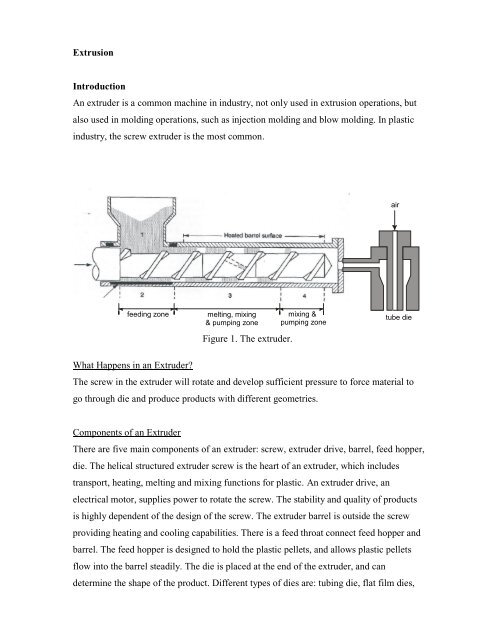
feed<strong>in</strong>g zone<br />
melt<strong>in</strong>g, mix<strong>in</strong>g<br />
& pump<strong>in</strong>g zone<br />
Figure 1. The <strong>extruder</strong>.<br />
mix<strong>in</strong>g &<br />
pump<strong>in</strong>g zone<br />
tube die<br />
What Happens <strong>in</strong> an Extruder<br />
The screw <strong>in</strong> the <strong>extruder</strong> will rotate and develop sufficient pressure to force material to<br />
go through die and produce products with different geometries.<br />
Components of an Extruder<br />
There are five ma<strong>in</strong> components of an <strong>extruder</strong>: screw, <strong>extruder</strong> drive, barrel, feed hopper,<br />
die. The helical structured <strong>extruder</strong> screw <strong>is</strong> the heart of an <strong>extruder</strong>, which <strong>in</strong>cludes<br />
transport, heat<strong>in</strong>g, melt<strong>in</strong>g and mix<strong>in</strong>g functions for plastic. <strong>An</strong> <strong>extruder</strong> drive, an<br />
electrical motor, supplies power to rotate the screw. The stability and quality of products<br />
<strong>is</strong> highly dependent of the design of the screw. The <strong>extruder</strong> barrel <strong>is</strong> outside the screw<br />
provid<strong>in</strong>g heat<strong>in</strong>g and cool<strong>in</strong>g capabilities. There <strong>is</strong> a feed throat connect feed hopper and<br />
barrel. The feed hopper <strong>is</strong> designed to hold the plastic pellets, and allows plastic pellets<br />
flow <strong>in</strong>to the barrel steadily. The die <strong>is</strong> placed at the end of the <strong>extruder</strong>, and can<br />
determ<strong>in</strong>e the shape of the product. Different types of dies are: tub<strong>in</strong>g die, flat film dies,
lown film dies, etc. In th<strong>is</strong> lab, we are us<strong>in</strong>g an annular structured tub<strong>in</strong>g die. Note that<br />
the size and shape of the extruded products will not be exactly the same as the size and<br />
shape of the die, because of several reasons: draw down, cool<strong>in</strong>g, swell<strong>in</strong>g and relaxation.<br />
Figure 2. The cross section of the die for tubes.<br />
<strong>Extrusion</strong> L<strong>in</strong>es<br />
For a complete extrusion process, <strong>in</strong> addition to <strong>extruder</strong>, upstream and downstream<br />
equipment <strong>is</strong> needed to produce useful products. The ma<strong>in</strong> equipment of an extrusion l<strong>in</strong>e<br />
<strong>is</strong> res<strong>in</strong> handl<strong>in</strong>g, dry<strong>in</strong>g system, <strong>extruder</strong>, post-shap<strong>in</strong>g or calibrat<strong>in</strong>g device, cool<strong>in</strong>g<br />
device, take-up device, and cutter or saw. The extrusion l<strong>in</strong>e <strong>in</strong> th<strong>is</strong> lab <strong>in</strong>cludes <strong>extruder</strong>,<br />
take-off roller and cool<strong>in</strong>g water trough, which are shown <strong>in</strong> Figure 3.<br />
Air<br />
Take-off roller<br />
Extruder<br />
Cool<strong>in</strong>g water trough<br />
Figure 3. The extrusion l<strong>in</strong>e <strong>in</strong> th<strong>is</strong> lab, <strong>in</strong>clud<strong>in</strong>g <strong>extruder</strong>, take-off roller and cool<strong>in</strong>g<br />
water trough.
Objectives for <strong>Extrusion</strong><br />
1. Determ<strong>in</strong>e the material volumetric feed<strong>in</strong>g rates based on different screw rotat<strong>in</strong>g<br />
speed (ω).<br />
2. F<strong>in</strong>d the tube dimensions based on different screw rotat<strong>in</strong>g speeds (ω), different takeoff<br />
speeds (v t ) and different pressure differences (p i ).<br />
3. Compare the experiment data with theoretical prediction.<br />
Proposed Goals<br />
1. Run the equipment and determ<strong>in</strong>e the volumetric feed<strong>in</strong>g rates based on different<br />
screw rotat<strong>in</strong>g speeds. Plot the volumetric feed<strong>in</strong>g rate versus screw rotat<strong>in</strong>g speed.<br />
Refer “Investigation of the Thickness (θ) of Tube with Different Screw Rotat<strong>in</strong>g<br />
Speeds (ω)” <strong>in</strong> Experimental Procedures.<br />
2. Plot the tube thickness versus screw rotat<strong>in</strong>g speed (ω), take-off speed (v t ) and<br />
pressure difference (p i ).<br />
Refer “Investigation of the Thickness (θ) of Tube with Different Screw Rotat<strong>in</strong>g<br />
Speeds (ω)”, “Investigation of the Thickness (θ) of Tube with Different Take-Off<br />
Speeds (v t )” and “Investigation of the Thickness (θ) of Tube with Different Pressure<br />
Differences (p i )” <strong>in</strong> Experimental Procedures, respectively.<br />
Internal air pressure<br />
(p i ) Hopper<br />
Die<br />
Screw<br />
Screw rotat<strong>in</strong>g speed<br />
(ω)<br />
Motor<br />
Motor<br />
Take-off speed<br />
(v t )<br />
Output material<br />
Figure 4. Scheme of control variables <strong>in</strong> th<strong>is</strong> experiment, where ω <strong>is</strong> the screw rotat<strong>in</strong>g<br />
speed, v t <strong>is</strong> the take-off speed of the roller and p i <strong>is</strong> the <strong>in</strong>ternal air pressure.
Theory<br />
Theoretical Background<br />
In th<strong>is</strong> lab, we are go<strong>in</strong>g to use an annular structured tub<strong>in</strong>g die to produce tubes <strong>in</strong><br />
different dimensions. When a polymer melt <strong>is</strong> extruded through an annular die and<br />
stretched under tension to a desired diameter, a hollow tube can be made. Although the<br />
overall process that <strong>in</strong>volves die swell followed by draw down (or stretch<strong>in</strong>g) <strong>is</strong> rather<br />
complicated as <strong>in</strong>dicated <strong>in</strong> Figure 5, analytic understand<strong>in</strong>g of the process can be made<br />
under some simplify<strong>in</strong>g assumptions.<br />
die exit<br />
die swell zone<br />
r<br />
z=0<br />
z<br />
r = R o (z)<br />
r = R i (z)<br />
u = (u, w)<br />
draw down region<br />
z=L<br />
F, w L<br />
Figure 5. The diagram for analyz<strong>in</strong>g polymer flow through the die.
In Figure 5., r and z are the radial and axial direction, respectively. R o (z) and R i (z) are the<br />
outer and <strong>in</strong>ner radius at different z position, respectively. The polymer flow<strong>in</strong>g velocity<br />
<strong>is</strong> def<strong>in</strong>ed as u, which <strong>in</strong>clud<strong>in</strong>g r-direction velocity u and z-direction velocity w.<br />
When a polymer melt flows out of the die exit, “die swell” occurs <strong>in</strong> that the polymer<br />
melt expands <strong>in</strong> the radial direction (i.e., swells) due to residual stress <strong>in</strong> the melt. Die<br />
swell <strong>is</strong> a very complicated phenomenon because it depends on the stra<strong>in</strong> h<strong>is</strong>tory (i.e.,<br />
memory effect) <strong>in</strong> the die as well as the rheological properties (both v<strong>is</strong>cous and<br />
v<strong>is</strong>coelastic) of the melt. Thus, prediction of it <strong>is</strong> very difficult. The die swell, however, <strong>is</strong><br />
restricted to a very short region near the die exit and an analytic progress can be made by<br />
simply neglect<strong>in</strong>g the die swell region and focus<strong>in</strong>g on the draw-down region.<br />
The simplify<strong>in</strong>g assumptions for the current analys<strong>is</strong> are<br />
a) Isothermal and ax<strong>is</strong>ymmetric flow<br />
b) Length of the draw-down region (L) <strong>is</strong> much longer than the radius of the exit hole of<br />
the die<br />
c) V<strong>is</strong>cous force <strong>is</strong> dom<strong>in</strong>ant and the v<strong>is</strong>coelastic force, <strong>in</strong>ertia, gravity and surface<br />
tension are negligible.<br />
d) Newtonian fluid<br />
Although polymer melts are non-Newtonian and the v<strong>is</strong>coelasticity effects are often<br />
important, the current flow of <strong>in</strong>terest <strong>is</strong> weakly extensional and slow. Furthermore, the<br />
shear stra<strong>in</strong> <strong>is</strong> also very weak throughout the entire draw-down region for th<strong>is</strong> free<br />
surface problem. Thus, the Newtonian assumption <strong>is</strong> not too restrictive. Consider<strong>in</strong>g that<br />
the v<strong>is</strong>cosity of polymer melts are quite high, assumption (c) <strong>is</strong> also not very restrictive.<br />
As the draw-down region <strong>is</strong> typically exposed to the air, the temperature may decrease as<br />
it flows down due to the cool<strong>in</strong>g by air. However, the temperature variation may not be<br />
very large unless air <strong>is</strong> blown aga<strong>in</strong>st the polymer melt for forced convective cool<strong>in</strong>g.<br />
We consider the cyl<strong>in</strong>drical coord<strong>in</strong>ates while determ<strong>in</strong><strong>in</strong>g the variables <strong>in</strong> the <strong>extruder</strong><br />
process. Figure 6. <strong>is</strong> the figure of a standard cyl<strong>in</strong>drical system.
Figure 6. Standard cyl<strong>in</strong>drical coord<strong>in</strong>ate<br />
Govern<strong>in</strong>g Equations<br />
Under the assumptions ((a)~(d)), the govern<strong>in</strong>g equations, cont<strong>in</strong>uity equation and the r-<br />
and z-directional momentum equation, for the flow <strong>in</strong> the draw-down region are as<br />
follows:<br />
1 <br />
r r ru<br />
p<br />
r<br />
p<br />
z<br />
<br />
<br />
( ) + w<br />
<br />
z = 0 (1)<br />
1<br />
<br />
<br />
2<br />
u <br />
ru<br />
<br />
<br />
(2)<br />
r<br />
<br />
r r<br />
1<br />
<br />
r<br />
<br />
<br />
2<br />
z <br />
2<br />
w w <br />
r <br />
r r 2<br />
z <br />
(3)<br />
As <strong>in</strong>dicated <strong>in</strong> Figure 5, u and w are the r- and z-directional component of the velocity<br />
vector u. R o (z) and R i (z) are the position of the outer and the <strong>in</strong>ner surface of the tube<br />
that should be also determ<strong>in</strong>ed as the solution along with u, w and p for th<strong>is</strong> free surface<br />
problem.<br />
The boundary conditions at the two free surfaces are follows,<br />
At r = R o (z),<br />
u<br />
<br />
<br />
<br />
<br />
R o<br />
z<br />
<br />
<br />
<br />
w<br />
<br />
0<br />
(4)
R o<br />
2 <br />
z<br />
p<br />
<br />
1 <br />
<br />
u<br />
<br />
<br />
<br />
r<br />
<br />
<br />
<br />
2<br />
R o<br />
z<br />
w<br />
z<br />
<br />
<br />
<br />
<br />
<br />
<br />
1 <br />
<br />
<br />
<br />
u<br />
<br />
2<br />
r<br />
<br />
<br />
<br />
<br />
<br />
<br />
<br />
<br />
<br />
2<br />
R<br />
<br />
o <br />
u<br />
<br />
z <br />
<br />
z<br />
<br />
R o <br />
u<br />
<br />
<br />
z <br />
z<br />
w<br />
r<br />
<br />
<br />
<br />
w<br />
<br />
r<br />
<br />
<br />
<br />
<br />
<br />
<br />
R o<br />
z<br />
0<br />
2<br />
<br />
<br />
<br />
<br />
w <br />
<br />
z <br />
<br />
(5)<br />
(6)<br />
At r = R i (z),<br />
u <br />
<br />
<br />
<br />
R i<br />
2 <br />
z<br />
p p i<br />
R i<br />
z<br />
<br />
<br />
<br />
w<br />
<br />
<br />
u<br />
<br />
<br />
<br />
r<br />
<br />
1 <br />
<br />
<br />
<br />
0<br />
w<br />
z<br />
2<br />
R i<br />
z<br />
<br />
<br />
<br />
<br />
<br />
<br />
1 <br />
<br />
<br />
<br />
<br />
<br />
<br />
u<br />
<br />
2<br />
r<br />
<br />
<br />
<br />
2<br />
R<br />
<br />
i <br />
u<br />
<br />
z <br />
<br />
z<br />
<br />
<br />
<br />
<br />
R i <br />
u<br />
<br />
<br />
z <br />
z<br />
w<br />
r<br />
w<br />
r<br />
<br />
<br />
<br />
<br />
<br />
<br />
<br />
<br />
<br />
<br />
<br />
0<br />
R i<br />
z<br />
2<br />
<br />
<br />
<br />
<br />
w <br />
<br />
z <br />
<br />
(7)<br />
(8)<br />
(9)<br />
Here (4) and (7) are the k<strong>in</strong>ematic conditions, (5) and (8) the tangential stress balances,<br />
and (6) and (9) are the normal stress balances at the outer and the <strong>in</strong>ner surfaces of the<br />
tube. In (9), p i <strong>is</strong> the pressure <strong>in</strong>side the tube (i.e., <strong>in</strong>ternal pressure) that can be<br />
controlled. That <strong>is</strong>, the <strong>in</strong>ner (hence the outer) radius can be controlled by vary<strong>in</strong>g the<br />
<strong>in</strong>ternal pressure when other conditions are fixed.<br />
At z = 0,<br />
R i<br />
ri<br />
, R o ro<br />
, w w o<br />
(10)<br />
At z = L,<br />
w w L<br />
(11)<br />
Here w o <strong>is</strong> the average velocity <strong>in</strong> the axial direction that <strong>is</strong> determ<strong>in</strong>ed once the output<br />
flow rate and the die geometry (i.e., r i and r o ) are specified. the axial velocity at z = L<br />
(i.e., position the fiber <strong>is</strong> quenched or solidified <strong>in</strong>stantaneously). w L <strong>is</strong> also known as the<br />
take-up velocity (v t ) that <strong>is</strong> controlled by the take-up device.
With boundary conditions occur at r = R o (z), r = R i (z), z = 0 and z = L, the <strong>in</strong>ner and<br />
outer surface profile can be determ<strong>in</strong>ed as follows.<br />
R ( z )<br />
i<br />
<br />
<br />
<br />
<br />
exp<br />
<br />
2<br />
i<br />
r<br />
<br />
<br />
<br />
(1 r<br />
2<br />
i<br />
) / w ( z )<br />
p<br />
i<br />
(1 w ( z )) <br />
<br />
<br />
w ( z ) <br />
2<br />
i<br />
r<br />
<br />
<br />
<br />
<br />
<br />
<br />
1 / 2<br />
(12)<br />
R<br />
o<br />
( z )<br />
<br />
<br />
R<br />
<br />
2<br />
i<br />
( z ) <br />
(1 r<br />
2<br />
i<br />
w ( z )<br />
) <br />
<br />
<br />
1 / 2<br />
(13)<br />
w<br />
( z ) exp <br />
z <br />
(14)<br />
<br />
w L<br />
ln <br />
w o<br />
<br />
<br />
<br />
(15)<br />
where r i and r o are known as the die geometry factors (i.e., <strong>in</strong>ner and outer diameters of<br />
exit of the die), w o <strong>is</strong> output rate at die exit and w L <strong>is</strong> the take-off velocity.<br />
Sample Calculations<br />
Figure 7 through 9 provide the theoretical predictions given by the equations (12) through<br />
(15) for the follow<strong>in</strong>g conditions:<br />
the outer radius of the die, r o : 2.788 mm (7/32” diameter)<br />
the <strong>in</strong>ner radius of the die, r i : 1.588 mm (1/8” diameter)<br />
draw span, L :<br />
v<strong>is</strong>cosity, :<br />
50 cm<br />
1000 Pa-s<br />
density, : 0.92 g/cm 3<br />
mass flow rate, m :<br />
take-up speed, w(L) :<br />
<strong>in</strong>ternal pressure, p i :<br />
50 g/m<strong>in</strong><br />
40 cm/s<br />
0 ~60 Pa
8.0<br />
7.0<br />
6.0<br />
5.0<br />
4.0<br />
3.0<br />
2.0<br />
1.0<br />
0.0<br />
W(z)<br />
0.0 0.2 0.4 0.6 0.8 1.0<br />
Figure 7. Dimensionless axial velocity<br />
1.0<br />
pi = 0 Pa<br />
1.0<br />
pi = 20 Pa<br />
0.8<br />
0.8<br />
0.6<br />
0.6<br />
0.4<br />
0.4<br />
0.2<br />
0.0<br />
Ro(z)<br />
Ri(z)<br />
0.0 0.2 0.4 0.6 0.8 1.0<br />
z<br />
(a)<br />
0.2<br />
0.0<br />
Ro(z)<br />
Ri(z)<br />
0.0 0.2 0.4 0.6 0.8 1.0<br />
z<br />
(b)<br />
1.0<br />
pi = 40 Pa<br />
1.0<br />
pi = 60 Pa<br />
0.8<br />
0.8<br />
0.6<br />
0.6<br />
0.4<br />
0.4<br />
0.2<br />
0.0<br />
Ro(z)<br />
Ri(z)<br />
0.0 0.2 0.4 0.6 0.8 1.0<br />
z<br />
(c)<br />
0.2<br />
0.0<br />
Ro(z)<br />
Ri(z)<br />
0.0 0.2 0.4 0.6 0.8 1.0<br />
z<br />
(d)<br />
Figure 8. Variation of <strong>in</strong>ner and outer radius of the tube at various <strong>in</strong>ternal pressure
0.7<br />
Ri(z)/Ro(z)<br />
(<strong>in</strong>creas<strong>in</strong>g pi)<br />
pi = 60 Pa<br />
0.6<br />
pi = 0 Pa<br />
0.5<br />
0.0 0.2 0.4 0.6 0.8 1.0<br />
Figure 9. Variation of <strong>in</strong>ner to outer radius ratio for various <strong>in</strong>ternal pressure<br />
Operat<strong>in</strong>g Procedures<br />
General Operations<br />
Start Up<br />
Die<br />
Off On<br />
Zone 3 Zone 2 Zone 1<br />
On Off Auto<br />
On Off Auto<br />
On Off Auto<br />
S D S 3 S 2 S 1<br />
Thermal meter<br />
for each zone<br />
T D T 3 T 2 T 1<br />
Ammeter for<br />
each zone<br />
Screw rotat<strong>in</strong>g speed<br />
15 rpm<br />
Stop<br />
Start<br />
Present temp. of die<br />
325 ℉<br />
Motor<br />
Motor speed<br />
controller<br />
Figure 10. The control panel of the extrusion system.
1. Switch the ma<strong>in</strong> power from “OFF” to “ON”.<br />
2. Turn the heat<strong>in</strong>g switches of Zone 1 (S 1 ), Zone 2 (S 2 ) and Zone 3 (S 3 ) to “Auto.” Turn<br />
the heat<strong>in</strong>g switch of Die (S D ) to “On.”<br />
3. Adjust the temperature of each zone to the desired temperature. (Goal temperature<br />
depends on the material we are us<strong>in</strong>g. For DYNH-1, the goal temperature T 1 =250°F<br />
T 2 =280°F, T 3 =280°F and T D =280°F)<br />
WARNING: EVERY PART OF THE EQUIPMENT IS EXTREMLY HOT. DON’T<br />
TOUCH IT.<br />
4. Wait until green light <strong>is</strong> d<strong>is</strong>played on every thermal meter, and check that the “present<br />
temperature of die” <strong>is</strong> the same as the goal temperature.<br />
5. Wait for another 15 m<strong>in</strong>utes to make sure the temperature of die <strong>in</strong>deed reaches the<br />
goal temperature.<br />
WARNING: EXTREMELY HOT POLYMER MAY SHOOT OUT AND<br />
SERIOUSLY HURT PEOPLE IF YOU FORGET TO WAIT ANOTHER 15<br />
MINUTES BEFORE STARTING.<br />
6. The equipment <strong>is</strong> ready to start.<br />
7. Place a water bath under die to cool down the output material.<br />
8. Make sure there are enough DYNH-1 beads <strong>in</strong> hopper.<br />
9. Press green “Start” button on the control panel.<br />
WARNING: NEVER STAND IN FRONT OF DIE SECTION AFTER START.<br />
10. Slowly adjust the motor speed to make the screw rotate at a certa<strong>in</strong> speed. (Stand<br />
beh<strong>in</strong>d the motor, you can see the screw rotation direction <strong>is</strong> counter-clockw<strong>is</strong>e.)<br />
11. Open the air valve.<br />
12. Introduce air <strong>in</strong>to the die to provide a certa<strong>in</strong> <strong>in</strong>ternal pressure (p i ).<br />
13. Open the feed gate of hopper to <strong>in</strong>troduce DYNH-1 beads <strong>in</strong>to barrel.<br />
Shut Down<br />
1. Close the feed gate of hopper.<br />
2. Let the screw run until barrel <strong>is</strong> empty, which means there <strong>is</strong> no more material go<strong>in</strong>g<br />
out.
3. Slowly adjust the motor speed to zero.<br />
4. Press red “Stop” button on the control panel.<br />
5. Turn off the switches of Zone 1 (S 1 ), Zone 2 (S 2 ) and Zone 3 (S 3 ) and Die (S D ) to<br />
“Off.”<br />
6. Switch the ma<strong>in</strong> power to “OFF.”<br />
7. Place the warn<strong>in</strong>g board near die section.<br />
WARNING: EVERY PART OF THE EQUIPMENT IS STILL EXTREMLY HOT.<br />
DON’T TOUCH IT.<br />
Experimental Procedures<br />
In th<strong>is</strong> experiment, different dimensions of tube will be obta<strong>in</strong>ed by chang<strong>in</strong>g three<br />
variables: screw rotation speed (ω), take-off speed (v t ) and <strong>in</strong>ternal pressure (p i ).<br />
D o (R o ) and m can be measured. Based on the conservation of mass shown as follows, D i<br />
(R i ) can be calculated.<br />
2<br />
D<br />
D v m<br />
2<br />
4<br />
o<br />
i<br />
t<br />
(16)<br />
where D o <strong>is</strong> the outer diameter of tube, which can be measured; ρ <strong>is</strong> the density of the<br />
material used <strong>in</strong> th<strong>is</strong> experiment, which <strong>is</strong> DYNH-1, and m <strong>is</strong> the mass feed<strong>in</strong>g rate,<br />
which <strong>is</strong> related to the screw rotation speed.<br />
NOTE: You can time and collect tube. Then, Weigh the rod and get the mass feed<strong>in</strong>g<br />
rate. Furthermore, divide the mass feed<strong>in</strong>g rate by density of DYNH-1, and volumetric<br />
feed<strong>in</strong>g rate can be obta<strong>in</strong>ed.<br />
Then, the thickness of the tube can be easily obta<strong>in</strong>ed.<br />
θ = R o − R i (17)
These are the experimental dimensions of tube. By compar<strong>in</strong>g experimental data with<br />
theoretical prediction, you can f<strong>in</strong>d out how the model works.<br />
Investigation of the Thickness of Tube with Different Screw Rotat<strong>in</strong>g Speeds<br />
1. Develop a table as follows:<br />
Table 1. Table for the dimensions of the tube with different screw rotat<strong>in</strong>g speeds,<br />
different take-off speeds and different pressure differences.<br />
ω<br />
(rpm)<br />
v t<br />
(m/s)<br />
p i<br />
(psi)<br />
Run 1 ω ○1 v t ○1 p i ○1<br />
Run 2 ω ○2 v t ○1 p i ○1<br />
Run 3 ω ○3 v t ○1 p i ○1<br />
Run 4 ω ○4 v t ○1 p i ○1<br />
Run 5 ω ○5 v t ○1 p i ○1<br />
Run 1 ω ○3 v t ○1 p i ○1<br />
Run 2 ω ○3 v t ○2 p i ○1<br />
Run 3 ω ○3 v t ○3 p i ○1<br />
Run 4 ω ○3 v t ○4 p i ○1<br />
Run 5 ω ○3 v t ○5 p i ○1<br />
Run 1 ω ○3 v t ○3 p i ○1<br />
Run 2 ω ○3 v t ○3 p i ○2<br />
Run 3 ω ○3 v t ○3 p i ○3<br />
Run 4 ω ○3 v t ○3 p i ○4<br />
Run 5 ω ○3 v t ○3 p i ○5<br />
m V<br />
(kg/m<strong>in</strong>) (m 3 /m<strong>in</strong>)<br />
SECTION 1<br />
SECTION 2<br />
SECTION 3<br />
w o<br />
(m/s)<br />
R o<br />
(mm)<br />
R i<br />
(mm)<br />
2. Fix the take-off speed, and slowly adjust motor speed to make the screw rotate at a<br />
certa<strong>in</strong> speed (rpm).<br />
3. Record the pressure gauge of the die section.<br />
4. Start to time and collect the tube.<br />
5. Weigh the tube and get the mass feed<strong>in</strong>g rate. Then, divide the mass feed<strong>in</strong>g rate by<br />
density of DYNH-1, and volumetric feed<strong>in</strong>g rate can be obta<strong>in</strong>ed.<br />
6. Calculate the output speed by divid<strong>in</strong>g the volumetric feed<strong>in</strong>g rate with cross area at<br />
the exit of die.<br />
θ<br />
(mm)
7. Measure the outer diameter (D o ) of the obta<strong>in</strong>ed tube to obta<strong>in</strong> outer radius (R o ).<br />
8. Calculate the <strong>in</strong>ner diameter (Di) from Eq. (16) to obta<strong>in</strong> <strong>in</strong>ner radius (R i ).<br />
9. Calculate the thickness (θ) from Eq. (17)<br />
10. Repeat several different screw rotat<strong>in</strong>g speeds to f<strong>in</strong><strong>is</strong>h section 1 <strong>in</strong> Table 1. (Choose<br />
at least 5 different screw rotat<strong>in</strong>g speeds.)<br />
11. Plot tube outer and <strong>in</strong>ner radius versus screw rotat<strong>in</strong>g speed and versus theoretical<br />
prediction.<br />
(Note: the diagrams may or may not be l<strong>in</strong>ear.)<br />
Investigation of the Thickness of Tube with Different Take-Off Speeds<br />
1. Fix the screw rotat<strong>in</strong>g speed and <strong>in</strong>ternal pressure (p i ), and adjust the take-off speed<br />
(v t ) to a certa<strong>in</strong> value.<br />
2. Record the pressure gauge of the die section.<br />
3. Refer to the previous section to get the volumetric feed<strong>in</strong>g rate at a specific screw<br />
rotat<strong>in</strong>g speed (rpm).<br />
4. Measure the outer diameter (D o ) of the obta<strong>in</strong>ed tube to obta<strong>in</strong> outer radius (R o ).<br />
5. Calculate the <strong>in</strong>ner diameter (Di) to obta<strong>in</strong> <strong>in</strong>ner radius (R i ) and thickness (θ) from<br />
Eq. (16) and Eq. (17), respectively.<br />
6. Repeat with several different take-off speeds to f<strong>in</strong><strong>is</strong>h section 2 <strong>in</strong> Table 1. (Choose at<br />
least 5 different take-off speeds.)<br />
7. Plot tube outer and <strong>in</strong>ner radius versus take-off speed and versus theoretical<br />
prediction.<br />
(Note: the diagrams may or may not be l<strong>in</strong>ear.)<br />
Investigation of the Thickness of Tube with Different Pressure Differences<br />
1. Fix the screw rotat<strong>in</strong>g speed and take-off speed, and adjust the <strong>in</strong>ternal pressure (p i ) to<br />
a certa<strong>in</strong> value.<br />
2. Record the pressure gauge of the die section.<br />
3. Refer to the previous section to get the volumetric feed<strong>in</strong>g rate at a specific screw<br />
rotat<strong>in</strong>g speed (rpm).<br />
4. Measure the outer diameter (D o ) of the obta<strong>in</strong>ed tube to obta<strong>in</strong> outer radius (R o ).
5. Calculate the <strong>in</strong>ner diameter (Di) to obta<strong>in</strong> <strong>in</strong>ner radius (R i ) and thickness (θ) from<br />
Eq. (16) and Eq. (17), respectively.<br />
6. Repeat with several different <strong>in</strong>ternal pressures to f<strong>in</strong><strong>is</strong>h section 3 <strong>in</strong> Table 1. (Choose<br />
at least 5 different <strong>in</strong>ternal pressures.)<br />
7. Plot tube outer and <strong>in</strong>ner radius versus <strong>in</strong>ternal pressure and versus theoretical<br />
prediction.<br />
(Note: the diagrams may or may not be l<strong>in</strong>ear.)<br />
Notations<br />
u Velocity factor (m/s)<br />
u r-directional component of the velocity vector u (m/s)<br />
w z-directional component of the velocity vector u (m/s)<br />
μ V<strong>is</strong>cosity of fluid (Pas)<br />
w o Output speed at die exit (m/s)<br />
w L Take-off speed (m/s)<br />
r o Outer radius at die exit (mm)<br />
r i Inner radius at die exit (mm)<br />
R o Outer radius of tube (mm)<br />
R i Inner radius of tube (mm)<br />
p i Internal pressure (pa)<br />
ω Screw rotat<strong>in</strong>g speed (rpm)<br />
v t Take-off speed (m/s)<br />
m Mass feed<strong>in</strong>g rate of DYNH-1 (kg/m<strong>in</strong>)<br />
V Volumetric feed<strong>in</strong>g rate of DYNH-1 (m 3 /m<strong>in</strong>)<br />
ρ Density of DYNH-1 (kg/m 3 )<br />
D o Outer diameter of tube (mm)<br />
D i Inner diameter of tube (mm)<br />
θ Thickness of tube (mm)<br />
Reference<br />
Dr. Chang-Won Park, <strong>Extrusion</strong> of Hollow Tubes<br />
Mark, H. F. (ed.), Encyclopedia of Polymer Science and Technology, Edition 3 rd ., John<br />
Wiley & Sons (2004) (Vol. 2)<br />
Stanley Middleman, Fundamentals of Polymer Process<strong>in</strong>g, McGraw Hill (1977)