Download manual - Systema Polska Sp. z o.o.
Download manual - Systema Polska Sp. z o.o.
Download manual - Systema Polska Sp. z o.o.

Create successful ePaper yourself
Turn your PDF publications into a flip-book with our unique Google optimized e-Paper software.
SYSTEMA S.p.A.<br />
CATOBA SETTING<br />
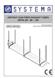
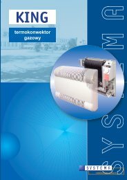
Airtight gas convectors<br />
Remove the plastic cover.<br />
Setting of the gas pressure to the pilot burner.<br />
Turn the setting knob in Pilot position (). To increase the capacity, turn the pilot adjustment<br />
screw counterclockwise and viceversa.<br />
Setting of the gas capacity to the main burner.<br />
Turn slowly the knob in low position until you hear the snap to have the low capacity), the<br />
knob position depends on the environment temperature. To increase the capacity, turn the<br />
low adjustment screw counterclockwise and viceversa.<br />
Setting of the (output) gas pressure to the main burner.<br />
The gas pressure is set at <strong>Systema</strong>'s premises and further resetting or adjustment must be<br />
done by skilled workers who can follow the following instructions.<br />
Turn the knob maximum to position 7 (the thermostatic bulb must be at the lowest temperature)<br />
Use a screwdriver take the seal cap off the from "9" pressure setting.<br />
To raise the output pressure, turn the screw "16" clockwise and viceversa.<br />
After resetting the boost control, it has to be in conformity with the UNI EN 126 regulation<br />
related to the boost control setting.<br />
After the settings put the seal cap on.<br />
Setting the boost control off duty.<br />
Use a screwdriver to take the seal cap off the "9" boost control.<br />
Turn the "16" screw clockwise totally UNTIL IT STARTS TO TURN IDLY, setting the boost<br />
control off duty (Gas III family).<br />
Put the seal cap on after the settings.<br />
3.7 Transformations for various types of gas supplies for<br />
electronic devices (Mod. K21E, K28E, K40E, K55E, K28VE,<br />
K40VE, K55VE, K21FE, K28FE, K40FE, K55FE)<br />
Transformation must be performed only by qualified professionals in complete respect of the<br />
safety regulations in force. The Manufacturer declines all liability for erroneous transformation<br />
or the inappropriate or incorrect use of the device.<br />
Transformation from Methane gas to LPG gas<br />
1) Close the gas supply line and disconnect the electrical power supply.<br />
2) Remove the cast-iron front panel by unscrewing the four M8 screws at the corners.<br />
3) Remove the gas supply line pipe from the main burner (4) using the sealing connector (5)<br />
(See Draw ).<br />
4) Remove the nozzle-holder (6) and the nozzle (7), and replace the nozzle with the one<br />
contained in the transformation kit after first checking to make sure that the diameter<br />
corresponds to the diameter listed on the rating plate.<br />
5) Disable the valve's pressure regulator by removing the brass plug (8) and then screwing<br />
the screw (3) clockwise (+) all the way down.<br />
6) Re-close the cast-iron front panel, making sure that the fiberglass sealing liner remains in<br />
place.<br />
Rev. 05IT0112-1<br />
30