MODeL LLes ejeCtOr sPrIng - Ziamatic Corp
MODeL LLes ejeCtOr sPrIng - Ziamatic Corp
MODeL LLes ejeCtOr sPrIng - Ziamatic Corp

You also want an ePaper? Increase the reach of your titles
YUMPU automatically turns print PDFs into web optimized ePapers that Google loves.
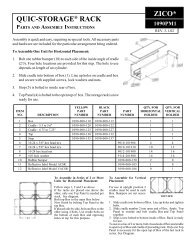
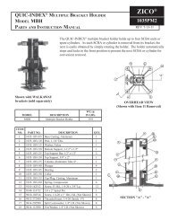
Knock-Down Bracket Parts & Assembly<br />
Model KD-ULLH "Load & Lock" brackets fit all<br />
SCBA units.<br />
KD-ULLH bracket kit contains the following:<br />
(component items are shown on page 3)<br />
1. Model UN (13) - Universal backplate<br />
2. Part Number: 1054-000-105 - Universal seats<br />
3. Model NSF (15) - Standard black coated short<br />
footplate - One per model of your choice (not<br />
required if valve assembly or end of cylinder will rest<br />
on a flat surface)<br />
4. Model LLS - "Load & Lock" strap<br />
5. Fastening screws and lock-nuts for attaching<br />
seats and footplate to universal backplate<br />
Assembly Instructions:<br />
1. Lay the self-contained breathing apparatus<br />
(SCBA) unit on a flat surface, floor or table.<br />
2. Lay universal backplate (13) along side of SCBA<br />
with six sets of parallel holes at same end as valve<br />
assembly on SCBA.<br />
• If mounting cylinder in inverted position, end<br />
of cylinder will be located at same end as<br />
parallel holes.<br />
3. Place one seat (14) at location "6" (see drawing).<br />
4. Place footplate (15) on universal backplate.<br />
NOTE: Short footplate may need to be inverted<br />
for some types of SCBA.<br />
a. Valve assembly should be placed next to<br />
footplate; valve will rest upon footplate on final<br />
assembly.<br />
b. Adjust SCBA cylinder so that cylinder will<br />
rest fully within the seat at location "6".<br />
5. Second seat (14) can now be placed at locations<br />
"1", "2", "3", or "4" (see drawing), so as to make full<br />
contact with the cylinder.<br />
6. Now that the proper seat mounting locations have<br />
been selected, proceed with assembly:<br />
a. Place flat head screws (10) through backplate<br />
(from countersunk side).<br />
b. Place seats and footplate over screws.<br />
c. Start nuts (11) onto screws.<br />
d. Tighten with 7/16" wrench and Torx head<br />
screw driver.<br />
e. Make sure that screws and nuts do not come<br />
into contact with air cylinder.<br />
NOTE: Seats are designed for 7/16" clearance<br />
between base of seat and the air cylinder.<br />
7. Securing "Load & Lock" strap onto universal<br />
backplate.<br />
a. Secure latch extension stamping (6) to<br />
universal backplate (see page 3 for position).<br />
b. Latch assembly (7) and lanyard (8) should<br />
already be attached to the latch extension. If<br />
not, connect them at this time.<br />
c. Attach strap retainers (5) to universal<br />
backplate at positions A & E (see above).<br />
8. To mount completed "Load & Lock" bracket to<br />
mounting surface, see instructions on pages 6, 7 or 8.<br />
Page 4