MODeL LLes ejeCtOr sPrIng - Ziamatic Corp
MODeL LLes ejeCtOr sPrIng - Ziamatic Corp
MODeL LLes ejeCtOr sPrIng - Ziamatic Corp

You also want an ePaper? Increase the reach of your titles
YUMPU automatically turns print PDFs into web optimized ePapers that Google loves.
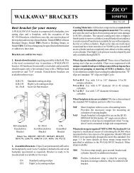
"LOAD & LOCK" Walkaway ® Brackets<br />
ZICO ®<br />
1054PM1<br />
Parts and Instruction Manual<br />
REV. 10-2-12<br />
"Where SCBA units are mounted within<br />
a driving or crew compartment, a positive<br />
latching mechanical means of holding the<br />
SCBA device in its stowed position shall be<br />
provided such that the SCBA unit cannot<br />
be retained in the mount unless the positive<br />
latch is engaged."<br />
The NFPA Standard requires the holding<br />
device to "retain the SCBA unit when<br />
subjected to a 9G force". Additionally, the<br />
"mounting devices shall be of a type that<br />
positively latch around the cylinder" and<br />
when mounted in a seat back, "the release<br />
mechanism shall be accessible to the user<br />
while seated".
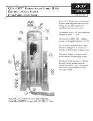
The "Load & Lock" SCBA bracket is composed of a<br />
backplate, two seats, a footplate, and a model LLS<br />
Strap.<br />
Brackets are available for purchase in two ways:<br />
1. Knock-down (model KD-ULLH):<br />
Requires assembly in the field. All hardware for<br />
assembly is included. Requires a few minutes time<br />
with a Torx head screwdriver and 7/16" wrench. The<br />
more economical option.<br />
Coating Materials: All bracket components are<br />
coated with a specially formulated thermoplastic<br />
material. This durable, crack/peel-resistant coating<br />
protects the bracket from rust, prevents wear damage<br />
to the air cylinder, and has been tested to over 50,000<br />
cycles. Only available from Zico.<br />
What seat size should be specified One size fits<br />
all. Seats are engineered with unique rounded ends<br />
to accommodate all cylinders, provide a smooth<br />
bearing surface, and prevent gouging or marring.<br />
Seats are double coated (high cycle yellow over<br />
black) for extra protection.<br />
What footplate styles are available The Model<br />
NSF standard short footplate is for 30 and 45 minute<br />
cylinders. An optional Model NEF footplate is<br />
recommended for 60 minute cylinders.<br />
What style strap is required NFPA 1901-04,<br />
Section 14.1.10.1 requires a mechanical means of<br />
restraining the SCBA when mounted in the crew area<br />
on a fire apparatus. Model LLS is specifically<br />
designed to meet this standard.<br />
KD-ULLH<br />
Knockdown Bracket<br />
(Shown without LLS strap)<br />
KD-ULLH<br />
Knockdown Bracket<br />
2. Assembled bracket (model ULLH):<br />
Bracket is assembled at our factory for immediate<br />
mounting. Seats (2) and footplate are bolted to the<br />
backplate and may need to be repositioned to achieve<br />
best fit for your SCBA.<br />
Can I convert my spring clip style bracket to a<br />
"Load & Lock" style bracket Model ULLH-CC<br />
provides (2) seats and (1) LLS strap to convert any<br />
spring clip style bracket.<br />
What if the SCBA unit stays in the bracket<br />
without the strap A Model LLES Ejector Spring<br />
must be added to your bracket to insure compliance<br />
with the NFPA Standard.<br />
Page 2
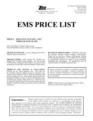
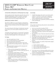
MODEL LLS "LOAD & LOCK" STRAP<br />
ITEM<br />
NO. PART NO. DESCRIPTION QTY.<br />
1 1010-140-904 Cambuckle/Tab Assembly 1<br />
2 1010-140-101 Main Strap 1<br />
3 1010-140-103 Adjustment Strap Assembly 1<br />
4 1010-140-105 1" Tri-Glide 2<br />
5 1010-120-055 Strap Retainer 2<br />
6 1010-120-175 Latch Extension Stamping 1<br />
7 1010-120-903 Latch Assembly 1<br />
8 1010-140-999 Lanyard 1<br />
10 9010-162511 1/4-20 x 5/8 Flat Head 12<br />
11 9013-172500 1/4-20 Lock Nut 14<br />
12 9010-102508 1/4-20 x 1/2 Hex Head 2<br />
MODEL KD-ULLH OR ULLH BRACKET<br />
13 UN Universal Backplate 1<br />
14 1054-007-105 Seat 2<br />
15 NSF Short Footplate 1<br />
On seats that are excessively<br />
tilted back, an Ejector Spring<br />
must be added to be sure the<br />
bracket is in compliance.<br />
Specify model LLES Ejector<br />
Spring.<br />
Page 3
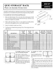
Knock-Down Bracket Parts & Assembly<br />
Model KD-ULLH "Load & Lock" brackets fit all<br />
SCBA units.<br />
KD-ULLH bracket kit contains the following:<br />
(component items are shown on page 3)<br />
1. Model UN (13) - Universal backplate<br />
2. Part Number: 1054-000-105 - Universal seats<br />
3. Model NSF (15) - Standard black coated short<br />
footplate - One per model of your choice (not<br />
required if valve assembly or end of cylinder will rest<br />
on a flat surface)<br />
4. Model LLS - "Load & Lock" strap<br />
5. Fastening screws and lock-nuts for attaching<br />
seats and footplate to universal backplate<br />
Assembly Instructions:<br />
1. Lay the self-contained breathing apparatus<br />
(SCBA) unit on a flat surface, floor or table.<br />
2. Lay universal backplate (13) along side of SCBA<br />
with six sets of parallel holes at same end as valve<br />
assembly on SCBA.<br />
• If mounting cylinder in inverted position, end<br />
of cylinder will be located at same end as<br />
parallel holes.<br />
3. Place one seat (14) at location "6" (see drawing).<br />
4. Place footplate (15) on universal backplate.<br />
NOTE: Short footplate may need to be inverted<br />
for some types of SCBA.<br />
a. Valve assembly should be placed next to<br />
footplate; valve will rest upon footplate on final<br />
assembly.<br />
b. Adjust SCBA cylinder so that cylinder will<br />
rest fully within the seat at location "6".<br />
5. Second seat (14) can now be placed at locations<br />
"1", "2", "3", or "4" (see drawing), so as to make full<br />
contact with the cylinder.<br />
6. Now that the proper seat mounting locations have<br />
been selected, proceed with assembly:<br />
a. Place flat head screws (10) through backplate<br />
(from countersunk side).<br />
b. Place seats and footplate over screws.<br />
c. Start nuts (11) onto screws.<br />
d. Tighten with 7/16" wrench and Torx head<br />
screw driver.<br />
e. Make sure that screws and nuts do not come<br />
into contact with air cylinder.<br />
NOTE: Seats are designed for 7/16" clearance<br />
between base of seat and the air cylinder.<br />
7. Securing "Load & Lock" strap onto universal<br />
backplate.<br />
a. Secure latch extension stamping (6) to<br />
universal backplate (see page 3 for position).<br />
b. Latch assembly (7) and lanyard (8) should<br />
already be attached to the latch extension. If<br />
not, connect them at this time.<br />
c. Attach strap retainers (5) to universal<br />
backplate at positions A & E (see above).<br />
8. To mount completed "Load & Lock" bracket to<br />
mounting surface, see instructions on pages 6, 7 or 8.<br />
Page 4
Converting KD-UN or KD-UH Bracket<br />
to KD-ULLH Bracket<br />
1. Remove bolts (1) and lock nuts (11) retaining the<br />
spring clips.<br />
2. Discard the spring clips and replace with seats<br />
(14).<br />
3. Remove bolts (10) and lock nuts (11) holding the<br />
model CRS strap to the universal backplate (13).<br />
4. Replace with "Load & Lock" strap attaching two<br />
strap retainers (5) to universal backplate using bolts<br />
(10) and lock nuts (11) provided.<br />
5. Lay the latch extension stamping (6) next to the<br />
one presently attached to your backplate (if you had<br />
a CRS stsrap). If they are the same size, you can use<br />
the extension (6), latch assembly (7), and lanyard (8)<br />
presently on your bracket. If the extension on your<br />
bracket is longer, remove the long extension and<br />
replace with the one provided.<br />
6. You are now ready to adjust the "Load & Lock"<br />
strap.<br />
Using the "Load & Lock" Walkaway Bracket<br />
Storage of SCBA:<br />
1. Place cylinder valve assembly on footplate.<br />
2. Tilt cylinder back until it is touching both seats<br />
and hold in place with one hand.<br />
3. With the other hand, bring the strap around the<br />
cylinder and insert the male tab into the latch.<br />
4. Pull the adjusting strap until it is tight around the<br />
cylinder.<br />
Release of SCBA:<br />
1. Place arms through shoulder straps, but do not<br />
tighten.<br />
2. Pull the release strap when the apparatus comes<br />
to a full and complete stop at the emergency scene<br />
and after the seat belt has been released.<br />
3. The LLS strap will pass between the SCBA unit<br />
and the firefighter.<br />
Page 5
Bracket Mounting On Mobile Fire Apparatus<br />
Mounting in crew area:<br />
When mounting SCBA brackets in the<br />
crew area, the model LLS "Load & Lock"<br />
Strap must be used with the bracket. The<br />
bracket with the LLS are designed to withstand<br />
a dynamic deceleration of ten (10)<br />
gravitational forces for a duration of ten<br />
(10) milliseconds.<br />
The surface to which the bracket is mounted<br />
should also be capable of withstanding a<br />
static force of ten (10) times the weight of<br />
the SCBA and bracket. If the bracket is<br />
mounted in a jump seat, then the seat<br />
assembly should also be capable of withstanding<br />
this same static force of ten (10)<br />
times the weight of the SCBA and bracket.<br />
Mounting hardware:<br />
The bracket should be mounted using<br />
two (2) 5/16-18 round head screws, nuts<br />
and lock washers (not provided). Refer to<br />
page 3 which shows the seat locations on<br />
the bracket. The center hole, at each seat<br />
location, is made for a 5/16" screw. We<br />
suggest the top screw be placed in seat<br />
location 1, 2 or 3. The bottom screw<br />
should be at seat locations 4 or 5. All<br />
mounting bolts and fasteners should be<br />
placed with the head in contact with the<br />
bracket and the screw portion passing<br />
through the bracket and supporting<br />
member. Nut and washer should be on the<br />
back side of the supporting member.<br />
Forward or rear facing seats:<br />
When mounted in specially designed SCBA seats, the bracket and LLS<br />
will meet the 10G force requirement with the LLS latch mounted on<br />
either side of the bracket. The angle between the back of the bracket and<br />
the mounting surface for the seat should be 90°. If the angle is less than<br />
90° in rear facing seats, a "stop" may be required at the top of the bracket<br />
to prevent the air cylinder from being ejected in the event of a collision.<br />
This stop could be a model NSF short footplate bolted to the top of the<br />
bracket or a metal device attached to the top of the pan holding the<br />
SCBA.<br />
NOTE: When the SCBA is placed into the<br />
bracket (without the LLS strap attached) it<br />
should fall out. If it does not, you will need to<br />
install model LLES Ejector Spring (page 3)<br />
to be in compliance with NFPA 1901-04.<br />
Side facing seats:<br />
When the bracket and LLS are mounted so that the<br />
passenger's side faces towards the front or rear of the<br />
apparatus, the LLS latch mechanism must be mounted<br />
on the side from which the force is coming.<br />
Page 6
Bracket Mounting On Mobile Fire Apparatus<br />
Mounting outside the crew area:<br />
When SCBA is mounted outside of the crew area, it<br />
is not subject to the 10G requirement and the "Load<br />
& Lock" bracket is not required. However, we<br />
recommend the following:<br />
Figure 1. Footplate should be mounted at the end<br />
towards which force is exterted when mounted on a<br />
flat surface.<br />
Figure 2. When the bracket is mounted vertically,<br />
the CRS or LLS latch should be on the side from<br />
which the force is applied and an additional stop<br />
should be placed against the air cylinder. An NSF<br />
footplate could be bolted to the mounting surface<br />
next to the cylinder.<br />
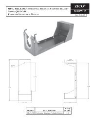
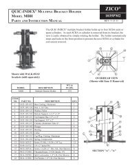
Model LLES Ejector Spring<br />
ITEM NO. PART NO. DESCRIPTION QTY.<br />
1 1054-015-105 Spring 1<br />
2 1045-275-113 Bumper 1<br />
3 9360-151207 Semi-tubular Rivet 1<br />
4 9010-162511 1/4-20 x 5/8 Flat Hd. 1<br />
5 9013-172500 1/4-20 Lock Nut 1<br />
Page 7
Proper Adjustment of "Load & Lock"<br />
Strap Model LLS<br />
See page 3 for parts list and<br />
page 4 for hole locations.<br />
Strap Attachment:<br />
• Strap retainers (5) attached below seat locations<br />
2 & 6 (see drawing page 3).<br />
• Strap retainers may be relocated so that straps (3)<br />
will not damage SCBA components.<br />
Strap Attachment:<br />
• "V" of strap should extend as far towards left or<br />
latch side of cylinder as possible.<br />
Latch Side:<br />
• Keep the adjustment strap assembly (3) as short<br />
as possible so that "V" of strap covers maximum<br />
surface of SCBA backplate.<br />
• Make sure strap (3) is "snugged" up so cylinder<br />
makes full contact with seats.<br />
If you have additional questions or are<br />
uncertain about mounting your ZICO<br />
bracket, call 1-800-711-3473 for assistance.<br />
www.ziamatic.com<br />
<strong>Ziamatic</strong> <strong>Corp</strong>.<br />
TOLL FREE: 800-711-3473<br />
10 West College Avenue, P.O. Box 337, Yardley, PA 19067-0587 • (215) 493-3618 • FAX: (215) 493-1401<br />
*ZICO is a registered trademark for fire, safety and marine products made by <strong>Ziamatic</strong> <strong>Corp</strong>. Copyright <strong>Ziamatic</strong> <strong>Corp</strong>. 10-12<br />
Page 8