RAKE Receiver
RAKE Receiver
RAKE Receiver

Create successful ePaper yourself
Turn your PDF publications into a flip-book with our unique Google optimized e-Paper software.
S-72.333 Postgraduate Course in Radio Communications, Autumn 2004 1<br />
<strong>RAKE</strong> <strong>Receiver</strong><br />
Tommi Heikkilä<br />
tommi.heikkila@teliasonera.com<br />
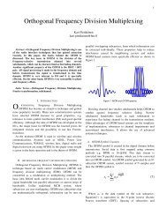
Abstract—<strong>RAKE</strong> receiver is used in CDMA-based (Code<br />
Division Multiple Access) systems and can combine multipath<br />
components, which are time-delayed versions of the original<br />
signal transmission. Combining is done in order to improve the<br />
signal to noise ration at the receiver. <strong>RAKE</strong> receiver attempts to<br />
collect the time-shifted versions of the original signal by<br />
providing a separate correlation receiver for each of the<br />
multipath signals. This can be done due to multipath<br />
components are practically uncorrelated from another when<br />
their relative propagation delay exceeds a chip period.<br />
This paper presents the basics of <strong>RAKE</strong> receiver<br />
technique, implementation, and design in cellular systems. Also<br />
the usage of <strong>RAKE</strong> receiver is introduced in CDMA-based<br />
systems such as IS-95 and WCDMA (Wideband Code Division<br />
Multiple Access).<br />
Index Terms—<strong>RAKE</strong> receiver, CDMA, multipath, receiver,<br />
maximal-ratio combining.<br />
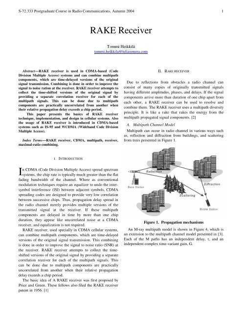
II. <strong>RAKE</strong> RECEIVER<br />
Due to reflections from obstacles a radio channel can<br />
consist of many copies of originally transmitted signals<br />
having different amplitudes, phases, and delays. If the signal<br />
components arrive more than duration of one chip apart from<br />
each other, a <strong>RAKE</strong> receiver can be used to resolve and<br />
combine them. The <strong>RAKE</strong> receiver uses a multipath diversity<br />
principle. It is like a rake that rakes the energy from the<br />
multipath propagated signal components. [2]<br />
A. Multipath Channel Model<br />
Multipath can occur in radio channel in various ways such<br />
as, reflection and diffraction from buildings, and scattering<br />
from trees presented in Figure 1.<br />
I<br />
I. INTRODUCTION<br />
n CDMA (Code Division Multiple Access) spread spectrum<br />
systems, the chip rate is typically much greater than the flat<br />
fading bandwidth of the channel. Where as conventional<br />
modulation techniques require an equalizer to undo the intersymbol<br />
interference (ISI) between adjacent symbols, CDMA<br />
spreading codes are designed to provide very low correlation<br />
between successive chips. Thus, propagation delay spread in<br />
the radio channel merely provides multiple versions of the<br />
transmitted signal at the receiver. If these multipath<br />
components are delayed in time by more than one chip<br />
duration, they appear like uncorrelated noise at a CDMA<br />
receiver, and equalization is not required.<br />
<strong>RAKE</strong> receiver, used specially in CDMA cellular systems,<br />
can combine multipath components, which are time-delayed<br />
versions of the original signal transmission. This combining<br />
is done in order to improve the signal to noise ratio (SNR) at<br />
the receiver. <strong>RAKE</strong> receiver attempts to collect the timeshifted<br />
versions of the original signal by providing a separate<br />
correlation receiver for each of the multipath signals. This<br />
can be done due to multipath components are practically<br />
uncorrelated from another when their relative propagation<br />
delay exceeds a chip period.<br />
The basic idea of A <strong>RAKE</strong> receiver was first proposed by<br />
Price and Green. These fellows also filed the <strong>RAKE</strong> receiver<br />
patent in 1956. [1]<br />
Figure 1. Propagation mechanisms<br />
An M-ray multipath model is shown in Figure 4, which is<br />
an extension to the multipath channel model presented in [3].<br />
Each of the M paths has an independent delay, , and an<br />
independent complex time-variant gain, G.
S-72.333 Postgraduate Course in Radio Communications, Autumn 2004 2<br />
t(t)<br />
Delay 1<br />
Delay 2<br />
.<br />
.<br />
.<br />
Delay M<br />
G 1 (t)<br />
G 2 (t)<br />
<br />
G M (t)<br />
Figure 2. Multipath channel model<br />
B. M-finger <strong>RAKE</strong> <strong>Receiver</strong><br />
Additive<br />
Gaussian<br />
Noise<br />
<br />
r(t)<br />
Multiple<br />
Access<br />
Interference<br />
A <strong>RAKE</strong> receiver utilizes multiple correlators to separately<br />
detect M strongest multipath components. The outputs of<br />
each correlator are weighted to provide better estimate of the<br />
transmitted signal than is provided by a single component.<br />
Demodulation and bit decisions are then based on the<br />
weighted outputs of the M correlators. [1]<br />
r(t)<br />
m 1 (t)<br />
m 2 (t)<br />
m M (t)<br />
Correlator 1<br />
Correlator 2<br />
.<br />
.<br />
.<br />
Correlator M<br />
Z 1<br />
1<br />
2 Z 2 Z’ Z T<br />
><br />
<br />
(.)dt<br />
Z M<br />
M<br />
Figure 3. An M-branch <strong>RAKE</strong> receiver implementation<br />
o<br />
<<br />
m’(t)<br />
Each correlator detects a time-shifted version of the<br />
original CDMA transmission, and each finger of the <strong>RAKE</strong><br />
correlates to a portion of the signal, which is delayed by at<br />
least one chip in time from the other fingers.<br />
Assume M correlators are used in a CDMA receiver to<br />
capture M strongest multipath components. A weighting<br />
network is used to provide a linear combination of the<br />
correlator output for bit decision. Correlator 1 is synchronized<br />
to the strongest multipath m 1 . Multipath component m 2<br />
arrived t 1 later than m 1 but has low correlation with m 1 .<br />
The M decision statistics are weighted to form an overall<br />
decision statistic as shown in Figure 3. The outputs of the M<br />
correlators are denoted as Z 1 , Z 2 ,…, and Z M . They are<br />
weighted by 1 , 2 ,…, and M , respectively. The weighting<br />
coefficients are based on the power or the SNR (Signal-to-<br />
Noise Ratio) from each correlator output. If the power or SNR<br />
is small out of a particular correlator, it will be assigned a<br />
small weighting factor, . If maximal-ratio combining is<br />
used, following equation 1 can be written for Z’.<br />
M<br />
Z' m Z (1)<br />
m<br />
m1<br />
The weighting coefficients, m , are normalized to the<br />
output signal power of the correlator in such a way that the<br />
coefficients sum to unity, as shown in following equation 2.<br />
2<br />
Z<br />
Z<br />
<br />
(2)<br />
m<br />
2<br />
m<br />
M<br />
m<br />
1<br />
m<br />
As in the case of adaptive equalizers and diversity<br />
combining, there are many ways to generate the weighting<br />
coefficients. However, due to Multiple Access Interference<br />
(MAI), <strong>RAKE</strong> fingers with strong multipath amplitudes will<br />
not necessarily provide strong output after correlation.<br />
Choosing weighting coefficients based on the actual outputs<br />
of the correlator yields better <strong>RAKE</strong> performance. [1]<br />
C. <strong>RAKE</strong> <strong>Receiver</strong> Block Diagram<br />
When a signal is received in a matched filter over a<br />
multipath channel, the multiple delays appear at the receiver,<br />
as depicted in Figure 4. The <strong>RAKE</strong> receiver uses several<br />
baseband correlators to individually process several signal<br />
multipath components. The correlator outputs are combined<br />
to achieve improved communications reliability and<br />
performance. [2]<br />
Bit decisions based only a single correlation may produce a<br />
large bit error rate as the multipath component processed in<br />
that correlator can be corrupted by fading. In a <strong>RAKE</strong><br />
receiver, if the output from one correlator is corrupted by<br />
fading, the others may not be, and the corrupted signal may<br />
be discounted through the weighting process. [1]<br />
Input<br />
RF signal<br />
Correlator<br />
Code<br />
generators<br />
Matched<br />
filter<br />
I<br />
Q<br />
Timing and finger allocation<br />
Channel<br />
estimators<br />
Phase<br />
rotator<br />
Delay<br />
equalizer<br />
Finger 1<br />
Finger 2<br />
Finger 3<br />
Figure 4. Block diagram of a <strong>RAKE</strong> receiver<br />
I<br />
Q<br />
Combiner<br />
Output<br />
Impulse response measurements of the multipath channel<br />
profile are executed through a matched filter to make a<br />
successful de-spreading. It reveals multipath channel peaks<br />
and gives timing and <strong>RAKE</strong> finger allocations to different<br />
receiver blocks. Later it tracks and monitors these peaks with<br />
a measurement rate depending on speeds of mobile station<br />
and on propagation environment. The number of available<br />
<strong>RAKE</strong> fingers depends on the channel profile and the chip<br />
rate. The higher the chip rate, the more resolvable paths there<br />
are, but higher chip rate will cause wider bandwidth. To catch<br />
all the energy from the channel more <strong>RAKE</strong> fingers are<br />
needed. A very large number of fingers lead to combining<br />
losses and practical implementation problems.
1. 1<br />
6<br />
5<br />
4<br />
3<br />
2<br />
1<br />
0<br />
0 20 4 0 6 0 8 0 1 0 0 1 2 0 14 0<br />
S-72.333 Postgraduate Course in Radio Communications, Autumn 2004 3<br />
III. <strong>RAKE</strong> RECEIVER IN IS-95 SYSTEM<br />
In the implementation of the IS-95 system, the mobile<br />
receiver employs a “searcher” receiver and three digital data<br />
receivers that act as fingers of a <strong>RAKE</strong> in that they may be<br />
assigned to track and isolate particular multipath components<br />
of a single cell site, a single base station in softer handover<br />
and multiple base stations in soft handover. The PN chip rate<br />
of 1,2288 MHz allows for resolution of multipaths at time<br />
intervals of 1,2288 x 10 -6 s = 0,814 s, which means that<br />
multipath difference in meters can be around 244 m. [4]<br />
A. Downlink<br />
The searcher receiver scans the time domain about the<br />
desired signal’s expected time of arrival for multipath pilot<br />
signals from the same cell site and pilot signals and their<br />
multipaths from other cell sites. Searching the time domain<br />
on the downlink signals is simplified because the pilot<br />
channel permits the coherent detection of signals. The search<br />
receiver indicates to the mobile phone’s control processor<br />
where, in time, the strongest replicas of the signal can be<br />
found, and their respective signal strengths. In turn, the<br />
control processor provides timing and PN code information to<br />
the tree digital data receivers, enabling each of them to track<br />
and demodulate a different signal. [4]<br />
If a another cell site pilot signal becomes significantly<br />
stronger than the current pilot signal, the control processor<br />
initiates handover procedures during which the downlinks of<br />
both cell sites transmit at the same call data on all their traffic<br />
channels. When both sites handle the call, additional space<br />
diversity or macro diversity is obtained. [4]<br />
The data from all three digital receivers are combined for<br />
improved resistance to fading. Different base stations or<br />
sectors are distinguished by different short PN code offsets.<br />
The downlink performs coherent post-detection combining<br />
after ensuring that the data streams are time-aligned;<br />
performance is not compromised by using post-detection<br />
combining because the modulation technique is linear.<br />
Coherent combining is possible because the pilot signal from<br />
each base station provides a coherent phase reference that can<br />
be tracked by the digital data receivers. [4]<br />
B. Uplink<br />
On the uplink, the base station receiver uses two antennas<br />
for space diversity reception, and there are four digital data<br />
receivers available for tracking up to four multipath<br />
components of a particular subscriber’s signal. The searcher<br />
receiver at the base station can distinguish the desired mobile<br />
signal by means of its unique scrambling long PN code offset,<br />
acquired before voice or data transmission begins on the link,<br />
using s special preamble for that purpose. [4]<br />
During soft handover from one base station site to another,<br />
the voice data that are selected could result from combining<br />
up to eight multipath components, four at each site. The<br />
uplink transmission, not having a coherent phase reference<br />
like the downlink’s pilot signal, must be demodulated and<br />
combined non-coherently; maximal-ratio combining can be<br />
done by weighting each path’s symbol statistics in proportion<br />
to the path’s relative power prior to demodulation and<br />
decoding decision. [4]<br />
IV. <strong>RAKE</strong> RECEIVER IN WCDMA SYSTEM<br />
A basic implementation of <strong>RAKE</strong> receiver presented in<br />
Figure 5 despreads data from different multipath components,<br />
combines the multipath components, and detects combined<br />
data to soft bits.<br />
A WCDMA base station <strong>RAKE</strong> receiver contains the<br />
following functions to enable the receiving of CDMA type of<br />
multipath signals. [5]<br />
1. Channel delay estimation for multipath components.<br />
This can also called as Impulse Response (IR) Measurement.<br />
2. <strong>RAKE</strong> receiver finger allocation based on the channel<br />
delay estimation<br />
3. <strong>RAKE</strong> receiver fingers to perform the descrambling and<br />
despreading operations<br />
4. Adaptive channel estimation<br />
5. Maximal-Ratio Combining (MRC)<br />
ANT<br />
A/D<br />
Impulse Respon se<br />
m easurement<br />
Matched<br />
Filters<br />
Chiprate<br />
Fin ger<br />
Allocation<br />
Co rrelator<br />
f inger 2<br />
finge r n<br />
Symbol Rat e<br />
Symbol<br />
Rate<br />
Rate<br />
f inger 1<br />
Comb iner<br />
C hannel<br />
Estimation<br />
Figure 5. <strong>RAKE</strong> receiver in WCDMA<br />
A. Channel Delay Estimation<br />
Soft<br />
Decision<br />
User<br />
Datarate<br />
The channel Impulse Response Measurement (IRM) is<br />
performed by using Matched Filter (MF) type of correlators<br />
that correlate the received signal with known reference code<br />
sequence such as pilot channel code.<br />
The MF resources contain shorter filters (length of 64 chips<br />
time period for RACH and 32 chips time period for DPCCH),<br />
which can be concatenated in time domain to enable the<br />
proper delay estimation also in large cells with large delay<br />
spreads (e.g. hilly terrain environments). [5]<br />
To improve the delay estimation performance and to<br />
increase signal to noise ratio the results of MFs are further<br />
processed by coherent and non-coherent averaging. The<br />
length of the coherent IR averaging is typically one time slot<br />
while the noncoherent averaging is typically done over radio<br />
frames. The length of the averaging operations can be<br />
selected by parametrization. The accuracy of the IR<br />
measurement is ¼ chip (65,1 ns). [5]
S-72.333 Postgraduate Course in Radio Communications, Autumn 2004 4<br />
B. <strong>RAKE</strong> <strong>Receiver</strong> Finger Allocation<br />
The purpose of the <strong>RAKE</strong> finger allocation procedure is to<br />
define the optimal finger delay positions that maximize the<br />
receiver performance. The allocation procedure defines the<br />
correct delay positions for despreading (in <strong>RAKE</strong> fingers) the<br />
received wideband signal to symbol level information. In the<br />
case of receiver antenna diversity the finger allocation<br />
procedure combines information from separate receiver<br />
antennas. In softer handover the allocation procedure defines<br />
the optimal finger delay positions by taking into account the<br />
information from all the sectors involved in the handover<br />
situation. [5]<br />
The finger allocation procedure contains algorithms, which<br />
eliminate the unnecessary changes in the finger time<br />
positions between successive allocations. Thus the<br />
despreading of a certain multipath component is kept on the<br />
same <strong>RAKE</strong> finger as long as possible to maximize the<br />
performance of channel estimation and maximal-ratio<br />
combining. [5]<br />
In the finger allocation procedure also the shape of the<br />
channel impulse response is taken into account when defining<br />
the optimum finger delay positions. It has been confirmed<br />
that the allocation must be done differently for the channels<br />
where the taps are very close to each others (so called "fat<br />
finger") than for channels with clearly separate taps. [5]<br />
Typically the allocation frequency in normal operation<br />
mode is one allocation for a code channel in every 25 ms<br />
(accuracy of ¼ chip), which is enough for all the practical<br />
situations. Code tracking with accuracy of 1/8 chip is further<br />
used in <strong>RAKE</strong> fingers to track and compensate small delay<br />
deviations in multipath component timing. The change in the<br />
timing can be caused by the movement of the UE or by the<br />
transmission timing adjustment of the UE. [5]<br />
C. <strong>RAKE</strong> <strong>Receiver</strong> Finger Descrambling and Despreading<br />
The despreading operation for DPDCH (Dedicated Physical<br />
Data Channel) and DPCCH (Dedicated Physical Control<br />
Channel) is performed in <strong>RAKE</strong> fingers to recover the<br />
receiver wideband signal to symbol level information -<br />
multiplying of incoming signal by complex conjugate of<br />
scrambling code and channelization code and accumulating<br />
the results over symbol periods. In the base station receiver 8<br />
fingers are allocated for each code channel (i.e. 8 multipath<br />
components can be despread for a single user). [5]<br />
Code tracking is used to track and compensate small<br />
deviations in multipath component delays i.e. the Code<br />
tracking performs the fine adjustment of the delay used in the<br />
despreading. The tracking is done for every finger and the<br />
accuracy is 1/8 chip. Like in the main finger allocation<br />
procedure the shape of the channel impulse response is taken<br />
into account when defining the despreading timings. [5]<br />
Typically the delay updating by code tracking is performed<br />
once in each or every second 10 ms radio frame. [5]<br />
D. Adaptive Channel Estimation<br />
The goal adaptive channel estimation is to estimate the<br />
characteristics of the time-variant channel. In WCDMA the<br />
solution is Pilot Symbol Aided plus adaptive filtering. [5]<br />
The channel estimation is used to remove distortion caused<br />
by radio channel and it is based on the known pilot symbols<br />
on DPCCH. The channel estimator filter adapts to the<br />
Doppler power spectrum (both frequency and the shape of the<br />
spectrum). The estimation is done for each finger separately.<br />
The use of adaptive filter ensures good performance in all<br />
kind of propagation conditions. The advantage of adaptive<br />
filter coefficients compared to use of fixed coefficient is<br />
evident since the solution with fixed coefficients would<br />
perform well only in a constricted set of propagation<br />
conditions. [5]<br />
In the case of multiple receiver antennas the performance<br />
of channel estimation is further improved by combining the<br />
power spectrum information available from different receiver<br />
antennas. [5]<br />
The combining process is based on maximal-ratio<br />
combining, which decreases the effect of additive noise,<br />
which can further be decreased by channel decoding.[5]<br />
E. Maximal-Ratio Combining (MRC)<br />
Maximal-Ratio Combining, first discussed by Brennan, is<br />
the optimal form of diversity combining because it yields<br />
the maximal SNR achievable. It requires the exact<br />
knowledge of SNRs as well as the phases of the diversity<br />
signals. [4]<br />
Figure 6. Maximal Ratio Combining in <strong>RAKE</strong><br />
After despreading the received symbol from transmitter via<br />
radio channel the symbols from allocated fingers are<br />
maximal-ratio-combined to construct the “combined” symbol.<br />
The output symbols from different fingers are multiplied with<br />
complex conjugate of the channel estimate and the result of<br />
multiplication is summed together into the “combined”<br />
symbol. This is illustrated in Figure 6 and Figure 7. [5]
S-72.333 Postgraduate Course in Radio Communications, Autumn 2004 5<br />
Finger Allocation<br />
Delay estimations<br />
1 2 n<br />
[4] Samuel C. Yang, CDMA RF System Engineering, Norwood MA, USA,<br />
Artech House Inc., 1998, 280 pp.<br />
[5] Mikko Järvelä, <strong>RAKE</strong> training slides by Nokia, 03.04.2001, Oulu.<br />
<strong>RAKE</strong> finger bank<br />
Finger 1<br />
r 1<br />
MRC combiner<br />
HOMEWORK<br />
RX RF<br />
ADC<br />
Finger 2<br />
r 2<br />
w1<br />
+<br />
Output<br />
1. Explain shortly the basic functions in a <strong>RAKE</strong> receiver.<br />
Finger n<br />
r n<br />
w2<br />
w n<br />
Channel<br />
estimator<br />
Figure 7. <strong>RAKE</strong> receiver using MRC<br />
F. Practical <strong>RAKE</strong> <strong>Receiver</strong> Requirements<br />
High bandwidth (5 MHz in WCDMA) and dynamic<br />
interference inherent to WCDMA requires that RF and IF<br />
parts have to operate linearly with large dynamic range.<br />
In practical <strong>RAKE</strong> receivers synchronization sets some<br />
requirements. Automatic Gain Control (AGC) loop is needed<br />
to keep the receiver at the dynamic range of the A/D<br />
converter. AGC must be fast and accurate enough to keep<br />
receiver at the linear range. Frame-by-frame data range<br />
change may set higher AGC and A/D (Analog-to-Digital)<br />
converter requirements. The high sampling rates of few tens<br />
of MHz and high dynamics of the input signal (80 dB)<br />
require fast A/D converters and high resolution. [5]<br />
Automatic Frequency Control (AFC) loop compensates for<br />
drift of the local oscillator and possibly compensates the<br />
Doppler shifts. Synchronization is required for channel<br />
impulse response measurements and scanning for <strong>RAKE</strong><br />
finger allocation. Also channel delay tracking needs<br />
synchronization for fine-adjustment and tracking of multipath<br />
components. [5]<br />
Pilots<br />
2. How many fingers can a Mobile Station <strong>RAKE</strong> receiver’s matched<br />
filter or “searcher” allocate from a following multipath tapped delay<br />
line channel in WCDMA and IS-95 systems Don’t guess!<br />
Tap 1 2 3 4 5 6<br />
Avg. 0 -1,5 -6,0 -4,5 -9,0 -15,5<br />
power (dB)<br />
Relative<br />
delay (ns)<br />
0 310 500 1090 2430 2510<br />
V. CONCLUSION<br />
This paper has introduced the basic operation and<br />
requirements of <strong>RAKE</strong> receiver used in CDMA based systems<br />
such as IS-95 and WCDMA. <strong>RAKE</strong> receiver attempts to<br />
collect the time-shifted versions of the original signal by<br />
providing a separate correlation receiver for each of the<br />
multipath signals. The <strong>RAKE</strong> receiver uses several baseband<br />
correlators to individually process several signal multipath<br />
components. The correlator outputs are combined to achieve<br />
improved communications reliability and performance.<br />
The basic functions of <strong>RAKE</strong> receiver are Channel delay<br />
estimation for multipath components, <strong>RAKE</strong> receiver finger<br />
allocation, descrambling and despreading operations,<br />
adaptive channel estimation, and Maximal-Ratio Combining.<br />
REFERENCES<br />
[1] Rappaport, Wireless Communications Principles and Practice, Prentice<br />
Hall, New Jersey, 1996, pp. 336-338.<br />
[2] Tero Ojanperä, Ramjee Prasad, Wideband CDMA for Third Generation<br />
Mobile Communications, Norwood MA, USA, Artect House Inc., 1998,<br />
439 pp.<br />
[3] Simon Haykin, Michael Moher: Modern Wireless Communications,<br />
Prentice Hall 2005, pp. 258-338.