KFD2-SR2-Ex2.W Switch Amplifier Connection Assembly ... - Ex-Baltic
KFD2-SR2-Ex2.W Switch Amplifier Connection Assembly ... - Ex-Baltic
KFD2-SR2-Ex2.W Switch Amplifier Connection Assembly ... - Ex-Baltic

You also want an ePaper? Increase the reach of your titles
YUMPU automatically turns print PDFs into web optimized ePapers that Google loves.
<strong>Switch</strong> <strong>Amplifier</strong><br />
<strong>KFD2</strong>-<strong>SR2</strong>-<strong><strong>Ex</strong>2.W</strong><br />
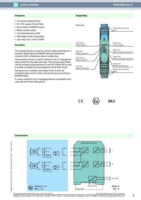
Features<br />
<strong>Assembly</strong><br />
• 2-channel isolated barrier<br />
• 24 V DC supply (Power Rail)<br />
• Dry contact or NAMUR inputs<br />
• Relay contact output<br />
• Line fault detection (LFD)<br />
• Reversible mode of operation<br />
• Up to SIL2 acc. to IEC 61508<br />
Function<br />
Front view<br />
LED yellow:<br />
Relay output Ι<br />
1 2 3<br />
4 5 6<br />
<strong>KFD2</strong>-<strong>SR2</strong>-<strong><strong>Ex</strong>2.W</strong><br />
1<br />
2<br />
OUT CHK PWR<br />
Removable terminals<br />
blue<br />
LED green:<br />
Power supply<br />
This isolated barrier is used for intrinsic safety applications. It<br />
transfers digital signals (NAMUR sensors/mechanical<br />
contacts) from a hazardous area to a safe area.<br />
The proximity sensor or switch controls a form C changeover<br />
relay contact for the safe area load. The normal output state<br />
can be reversed using switches S1 and S2. <strong>Switch</strong> S3 is used<br />
to enable or disable line fault detection of the field circuit.<br />
During an error condition, the relays revert to their deenergized<br />
state and the LEDs indicate the fault according to<br />
NAMUR NE44.<br />
A unique collective error messaging feature is available when<br />
used with the Power Rail system.<br />
LED red:<br />
LB/SC channel Ι<br />
LED yellow:<br />
Relay output ΙΙ<br />
LED red:<br />
LB/SC channel ΙΙ<br />
S1<br />
S2<br />
S3<br />
I<br />
II<br />
7 8 9<br />
10 11 12<br />
13 14 15<br />
<strong>Switch</strong> S1<br />
(Mode of operation channel Ι)<br />
<strong>Switch</strong> S2<br />
(Mode of operation channel ΙΙ)<br />
<strong>Switch</strong> S3<br />
(LB/SC-monitoring)<br />
Removable terminals<br />
green<br />
2<br />
<strong>Connection</strong><br />
Release date 2011-07-06 16:36 Date of issue 2011-07-06 132960_eng.xml<br />
I<br />
II<br />
Zone 0, 1, 2<br />
Div. 1, 2<br />
10 kΩ<br />
400 Ω ≤ R ≤ 2 kΩ<br />
10 kΩ<br />
400 Ω ≤ R ≤ 2 kΩ<br />
10 kΩ<br />
10 kΩ<br />
1+<br />
2+<br />
3-<br />
4+<br />
5+<br />
6-<br />
<strong>KFD2</strong>-<strong>SR2</strong>-<strong><strong>Ex</strong>2.W</strong><br />
ERR 24 V DC<br />
Power Rail<br />
7<br />
8<br />
9<br />
10<br />
11<br />
12<br />
14+<br />
15-<br />
I<br />
II<br />
24 V DC<br />
Zone 2<br />
Div. 2<br />
Subject to reasonable modifications due to technical advances.<br />
Copyright Pepperl+Fuchs, Printed in Germany<br />
Pepperl+Fuchs Group • Tel.: Germany +49-621-776-0 • USA +1-330-4253555 • Singapore +65-67-799091 • Internet www.pepperl-fuchs.com 1
Technical data<br />
<strong>KFD2</strong>-<strong>SR2</strong>-<strong><strong>Ex</strong>2.W</strong><br />
Release date 2011-07-06 16:36 Date of issue 2011-07-06 132960_eng.xml<br />
General specifications<br />
Signal type<br />
Supply<br />
Digital Input<br />
<strong>Connection</strong> Power Rail or terminals 14+, 15-<br />
Rated voltage<br />
20 ... 30 V DC<br />
Ripple ≤ 10 %<br />
Rated current<br />
≤ 50 mA<br />
Power loss<br />
1 W<br />
Power consumption<br />
< 1.3 W<br />
Input<br />
<strong>Connection</strong> terminals 1+, 2+, 3-; 4+, 5+, 6-<br />
Rated values<br />
acc. to EN 60947-5-6 (NAMUR)<br />
Open circuit voltage/short-circuit current approx. 8 V DC / approx. 8 mA<br />
<strong>Switch</strong>ing point/switching hysteresis 1.2 ... 2.1 mA / approx. 0.2 mA<br />
Line fault detection<br />
breakage I ≤ 0.1 mA , short-circuit I > 6 mA<br />
Pulse/Pause ratio<br />
≥ 20 ms / ≥ 20 ms<br />
Output<br />
<strong>Connection</strong> output I: terminals 7, 8, 9 ; output II: terminals 10, 11, 12<br />
Output I, II<br />
Minimum switch current<br />
Energized/De-energized delay<br />
Mechanical life<br />
Transfer characteristics<br />
<strong>Switch</strong>ing frequency<br />
Electrical isolation<br />
Output/power supply<br />
Output/Output<br />
Directive conformity<br />
signal, relay<br />
2 mA / 24 V DC<br />
approx. 20 ms / approx. 20 ms<br />
10 7 switching cycles<br />
≤ 10 Hz<br />
reinforced insulation according to IEC 61140, rated insulation voltage 300 V eff<br />
reinforced insulation according to IEC 61140, rated insulation voltage 300 V eff<br />
Electromagnetic compatibility<br />
Directive 2004/108/EC EN 61326-1:2006<br />
Low voltage<br />
Directive 2006/95/EC EN 50178:1997<br />
Conformity<br />
Electromagnetic compatibility NE 21<br />
Protection degree IEC 60529<br />
Protection against electric shock IEC 61140<br />
Ambient conditions<br />
Ambient temperature<br />
-20 ... 60 °C (-4 ... 140 °F)<br />
Mechanical specifications<br />
Protection degree<br />
IP20<br />
Mass<br />
approx. 150 g<br />
Dimensions<br />
20 x 119 x 115 mm (0.8 x 4.7 x 4.5 in) , housing type B2<br />
Data for application in connection<br />
with <strong>Ex</strong>-areas<br />
EC-Type <strong>Ex</strong>amination Certificate PTB 00 ATEX 2080 , for additional certificates see www.pepperl-fuchs.com<br />
Group, category, type of protection ¬ II (1) G [<strong>Ex</strong> ia] IIC, II (1) D [<strong>Ex</strong> ia] IIIC<br />
Input<br />
[<strong>Ex</strong> ia] IIC, [<strong>Ex</strong> ia] IIIC<br />
Voltage U o 10.5 V<br />
Current I o 13 mA<br />
Power P o 34 mW (linear characteristic)<br />
Supply<br />
Maximum safe voltage U m 253 V AC / 125 V DC (Attention! U m is no rated voltage.)<br />
Output<br />
Contact loading<br />
253 V AC/2 A/cos φ > 0.7; 126.5 V AC/4 A/cos φ > 0.7; 40 V DC/2 A resistive load<br />
Maximum safe voltage U m 253 V AC (Attention! The rated voltage can be lower.)<br />
Statement of conformity<br />
Group, category, type of protection<br />
Pepperl+Fuchs<br />
¬ II (3)G [<strong>Ex</strong> ic] IIC; [<strong>Ex</strong> nL] IIC<br />
Input<br />
[<strong>Ex</strong> ic] IIC; [<strong>Ex</strong> nL] IIC<br />
Voltage U o 10.5 V<br />
Current I o 13 mA<br />
Power P o 34 mW (linear characteristic)<br />
Output<br />
Contact loading<br />
253 V AC/2 A/cos φ > 0.7; 126.5 V AC/4 A/cos φ > 0.7; 40 V DC/2 A resistive load<br />
Statement of conformity<br />
TÜV 99 ATEX 1493 X , observe statement of conformity<br />
Subject to reasonable modifications due to technical advances.<br />
Copyright Pepperl+Fuchs, Printed in Germany<br />
Pepperl+Fuchs Group • Tel.: Germany +49-621-776-0 • USA +1-330-4253555 • Singapore +65-67-799091 • Internet www.pepperl-fuchs.com 2
Technical data<br />
<strong>KFD2</strong>-<strong>SR2</strong>-<strong><strong>Ex</strong>2.W</strong><br />
Group, category, type of protection,<br />
temperature classification<br />
Output<br />
Contact loading<br />
¬ II 3G <strong>Ex</strong> nA nC IIC T4<br />
50 V AC/4 A/cos φ > 0.7; 40 V DC/2 A resistive load<br />
Electrical isolation<br />
Input/Output<br />
safe electrical isolation acc. to IEC/EN 60079-11, voltage peak value 375 V<br />
Input/power supply<br />
safe electrical isolation acc. to IEC/EN 60079-11, voltage peak value 375 V<br />
Directive conformity<br />
Directive 94/9/EC EN 60079-0:2009, EN 60079-11:2007 , EN 61241-11:2006 , EN 60079-0:2006, EN 60079-15:2005<br />
International approvals<br />
FM approval<br />
Control drawing 116-0035<br />
CSA approval<br />
Control drawing 116-0047<br />
IEC<strong>Ex</strong> approval IEC<strong>Ex</strong> PTB 11.0034<br />
Approved for<br />
[<strong>Ex</strong> ia] IIC , [<strong>Ex</strong> ia] IIIC , [<strong>Ex</strong> ia] I<br />
General information<br />
Supplementary information<br />
EC-Type <strong>Ex</strong>amination Certificate, Statement of Conformity, Declaration of Conformity, Attestation of<br />
Conformity and instructions have to be observed where applicable. For information see www.pepperlfuchs.com.<br />
Release date 2011-07-06 16:36 Date of issue 2011-07-06 132960_eng.xml<br />
Subject to reasonable modifications due to technical advances.<br />
Copyright Pepperl+Fuchs, Printed in Germany<br />
Pepperl+Fuchs Group • Tel.: Germany +49-621-776-0 • USA +1-330-4253555 • Singapore +65-67-799091 • Internet www.pepperl-fuchs.com 3
Technical data<br />
<strong>KFD2</strong>-<strong>SR2</strong>-<strong><strong>Ex</strong>2.W</strong><br />
Configuration<br />
<strong>Switch</strong> position<br />
S Function Position<br />
1 Mode of operation<br />
Output I (relay)<br />
energized<br />
with high input current<br />
with low input current<br />
I<br />
II<br />
1 2 3<br />
4 5 6<br />
1<br />
OUT CHK PWR<br />
2<br />
S1<br />
S2<br />
S3<br />
1 2 3<br />
7 8 9<br />
10 11 12<br />
13 14 15<br />
S1<br />
S2<br />
S3<br />
1 2 3<br />
I<br />
II<br />
2 Mode of operation with high input current I<br />
Output II (relay)<br />
with low input current II<br />
energized<br />
3 Line fault detection ON I<br />
OFF<br />
II<br />
Operating status<br />
Control circuit<br />
Initiator high impedance/<br />
contact opened<br />
Initiator low impedance/<br />
contact closed<br />
Lead breakage,<br />
lead short-circuit<br />
Input signal<br />
low input current<br />
high input current<br />
Line fault<br />
Factory settings: switch 1, 2 and 3 in position I<br />
Accessories<br />
Power feed modules <strong>KFD2</strong>-EB2...<br />
The power feed module is used to supply the devices with 24 V DC via the Power Rail. The fuse-protected power feed module<br />
can supply up to 100 individual devices depending on the power consumption of the devices. A galvanically isolated mechanical<br />
contact uses the Power Rail to transmit collective error messages.<br />
Power Rail UPR-03<br />
The Power Rail UPR-03 is a complete unit consisting of the electrical inset and an aluminium profile rail 35 mm x 15 mm. To make<br />
electrical contact, the devices are simply engaged.<br />
The Power Rail must not be fed via the device terminals of the individual devices!<br />
Release date 2011-07-06 16:36 Date of issue 2011-07-06 132960_eng.xml<br />
Subject to reasonable modifications due to technical advances.<br />
Copyright Pepperl+Fuchs, Printed in Germany<br />
Pepperl+Fuchs Group • Tel.: Germany +49-621-776-0 • USA +1-330-4253555 • Singapore +65-67-799091 • Internet www.pepperl-fuchs.com 4