Scantech Pollux P-4010 Bar code laser scanner - Champtek
Scantech Pollux P-4010 Bar code laser scanner - Champtek
Scantech Pollux P-4010 Bar code laser scanner - Champtek

You also want an ePaper? Increase the reach of your titles
YUMPU automatically turns print PDFs into web optimized ePapers that Google loves.
u s e r ’ s m a n u a l<br />
<strong>Scantech</strong> <strong>Pollux</strong> P-<strong>4010</strong><br />
<strong>Bar</strong> <strong>code</strong> <strong>laser</strong> <strong>scanner</strong>
User's manual<br />
<strong>Scantech</strong> <strong>Pollux</strong> P-<strong>4010</strong>
Copyright © 2007, <strong>Scantech</strong>-ID BV.<br />
This manual is copyrighted, with all rights reserved. Under the copyright laws, this manual may not, in<br />
whole or in part, be copied, photocopied, reproduced, translated or converted to any electronic medium<br />
or machine readable form without prior written consent of <strong>Scantech</strong>-ID BV.<br />
Limited Warranty<br />
Under all circumstances this manual should be read attentively, before installing and/or using the product.<br />
In no event <strong>Scantech</strong>-ID BV will be liable for any direct, indirect, special, consequential or<br />
incidental damages arising out of the use or inability to use this documentation or product, even if<br />
advised of the possibility of such damages. In particular, <strong>Scantech</strong>-ID BV shall not be liable for any<br />
hardware, software, or data that is stored or used with the product, including the cost of repairing,<br />
replacing or recovering the above. <strong>Scantech</strong>-ID BV reserves the right to change parts of the device<br />
at any time without preceding or direct announcement to the client.<br />
<strong>Scantech</strong>-ID BV reserves the right to revise this manual, and to make changes in the contents without<br />
obligation to notify any person or entity of the revision or change. A serial number appears on the<br />
product. Make sure that this official registration number has not been removed. It should be used<br />
whenever servicing by <strong>Scantech</strong>-ID BV or an authorized <strong>Scantech</strong> dealer is necessary.<br />
Important<br />
This equipment has been tested and found to comply with the limits for a Class B digital device, pursuant<br />
to EN55022, and with the limits for a class A digital device, pursuant to part 15 of the FCC rules.<br />
These limits are designed to provide reasonable protection against harmful interference when the equipment<br />
is operated in a commercial environment. This equipment generates, uses, and can radiate radio<br />
frequency energy and, if not installed and used in accordance with the user’s manual, may cause harmful<br />
interference to radio communications. Operation of the equipment in a residential area is likely to cause<br />
harmful interference in which case the user will be required to correct the interference at his own<br />
expense. Any unauthorized changes or modifications to this equipment could void the user’s authority to<br />
operate this equipment.<br />
For CE-countries:<br />
- The <strong>Pollux</strong> is in conformity with the CE standards. Please note that a <strong>Scantech</strong> CE-marked power<br />
supply unit should be used to conform to these standards.<br />
For USA & Canada:<br />
- To be used with UL listed and CSA certified computers/POS systems. This <strong>scanner</strong> should only be powered<br />
by a UL Listed/CSA Certified power supply having Limited Power Source or Class2 outputs,<br />
rated + 5 V dc/0.75A, + 12 V dc/1A, -12 V dc/0.05A and minimum 40 degrees Celcius operating<br />
environment.<br />
- À utiliser avec des ordinateurs/systèmes POS registrés UL/certifiés CSA.<br />
Radio and television interference<br />
Operation of this equipment in a residential area can cause interference to radio or television reception.<br />
This can be determined by turning the equipment off and on. The user is encouraged to try to correct<br />
the interference by one or more of the following measures:<br />
• Re-orientate the receiving antenna<br />
• Relocate the device with respect to the receiver<br />
• Move the device away from the receiver<br />
• Plug the device into a different outlet in order to have the device and<br />
receiver on different branch circuits<br />
If necessary, the user should consult the manufacturer, an authorized <strong>Scantech</strong> dealer or experienced<br />
radio/television technician for additional suggestions. The booklet "How to Identify and Resolve Radio-TV<br />
Interference Problems", prepared by the Federal Communications Commission, can be of help. It can be<br />
obtained from the U.S. Government Printing Office, Washington, DC 20402, Stock No. 004000003454.<br />
P/N A0920013 January 2007
Table of contents<br />
Preface<br />
i<br />
Chapter 1 The <strong>Pollux</strong> P-<strong>4010</strong> 1<br />
1.1 Unpacking the <strong>Pollux</strong> P-<strong>4010</strong> 2<br />
1.2 Scanning bar <strong>code</strong>s with the <strong>Pollux</strong> P-<strong>4010</strong> 4<br />
1.3 Scanner labelling 6<br />
1.4 Maintaining the <strong>scanner</strong> 9<br />
1.5 Controlling the <strong>scanner</strong> from the POS system 9<br />
Chapter 2 Installing the <strong>Pollux</strong> P-<strong>4010</strong> 11<br />
2.1 Installing the <strong>scanner</strong> on a counter surface 13<br />
Chapter 3 Mounting options <strong>Pollux</strong> P-<strong>4010</strong> 17<br />
3.1 Flyby mode scanning: right to left 19<br />
3.2 Flyby mode scanning: left to right 21<br />
3.3 Presentation mode scanning 23<br />
Appendices A. Connector types and pin definitions 26<br />
B. Technical specifications 28<br />
C. Troubleshooting 30
Preface<br />
The <strong>Pollux</strong> P-<strong>4010</strong> is an innovative, high performance food retail <strong>scanner</strong>, combining<br />
unequalled performances with enormous installation flexibility. It has a<br />
unique four-directional sealed optical assembly, allowing it to be turned inside<br />
the fixed <strong>scanner</strong> housing. This new benchmark for vertical supermarket and<br />
hypermarket scanning ensures an ergonomic and user-friendly implementation<br />
wherever it is installed. The <strong>Pollux</strong> is also one of the flattest <strong>scanner</strong>s available<br />
today, making installation at the check-out even easier.<br />
The dense scan pattern of the <strong>Pollux</strong> guarantees excellent omni-directional bar<br />
<strong>code</strong> reading and the new Scantium de<strong>code</strong>r chip gives the <strong>scanner</strong> unrivalled<br />
multi-decoding power. An important feature of the <strong>Pollux</strong> is the Goldrush polygon<br />
technology. Evaporated gold on the polygon makes it ultra light, giving longer<br />
motor life and faster ‘wake-up’ times from the energy saving sleep mode.Two<br />
versions of the <strong>Pollux</strong> are available, one unit has RS232C and OCIA interfaces<br />
and the other has IBM RS485 and Keyboard Wedge interfaces. An auxiliary port<br />
for connecting another <strong>Scantech</strong> <strong>scanner</strong> is standard.<br />
This manual contains three chapters and three appendices. The first chapter<br />
describes the <strong>Pollux</strong> and its general features.<br />
Instructions for the installation are described in the second chapter.<br />
Precisely follow the instructions for the installation of the <strong>scanner</strong>.<br />
Default settings can be changed with the bar <strong>code</strong> labels from the Configuration<br />
Guide that came with the <strong>scanner</strong>.<br />
The third chapter describes all possible mounting options.<br />
Appendix A shows all connectors of the <strong>scanner</strong>. Technical specifications of the<br />
<strong>Pollux</strong> can be found in Appendix B. Refer to Appendix C for troubleshooting if the<br />
<strong>scanner</strong> is not working properly.
Chapter 1<br />
The <strong>Pollux</strong> P-<strong>4010</strong>
2 The <strong>Pollux</strong> P-<strong>4010</strong><br />
1.1 UNPACKING THE POLLUX P-<strong>4010</strong><br />
Remove the <strong>scanner</strong> and its accessories from the box and packing material.<br />
Refer to the packing list to make sure you have received all the items ordered.<br />
Visually inspect the <strong>scanner</strong> and accessories for any evidence of physical damage.<br />
Refer to the figure on page 6 to locate the interface label and make sure<br />
that the <strong>scanner</strong> interface corresponds with the host system interface.<br />
Immediately contact your supplier if anything appears to be damaged, or if the<br />
supported interface does not correspond with the host system interface.<br />
The various parts of the <strong>Pollux</strong> P-<strong>4010</strong> are:<br />
THE POLLUX P-<strong>4010</strong><br />
LED<br />
Sleep mode switch<br />
POLLUX<br />
Good read speaker
The <strong>Pollux</strong> P-<strong>4010</strong> 3<br />
The various parts of the <strong>Pollux</strong> P-<strong>4010</strong> are:<br />
Sleep mode switch - When a sleep mode time-out is programmed, the -<br />
<strong>scanner</strong> can be re-activated by pressing this switch.<br />
The sleep-mode feature is programmable with the<br />
menu labels from the Configuration Guide.<br />
NOTE: The default value for the sleep mode time-out<br />
is set to 30 minutes. When the <strong>scanner</strong> is in<br />
sleep mode, the LED is intermittently flashing<br />
red.<br />
LED<br />
- A red LED indicates that the <strong>scanner</strong> is ready to read<br />
a bar <strong>code</strong>. A green LED indicates a good read.<br />
Good read speaker<br />
- The speaker is heard whenever data has been read correctly.<br />
The frequency and volume can be adjusted with<br />
the menu labels from the Configuration Guide.
4 The <strong>Pollux</strong> P-<strong>4010</strong><br />
1.2 SCANNING BAR CODES WITH THE POLLUX P-<strong>4010</strong><br />
The <strong>Pollux</strong> P-<strong>4010</strong> is an omni-directional <strong>scanner</strong> featuring a 5 directional scan<br />
field with a 20 lines scan pattern. The <strong>scanner</strong>'s scan volume is illustrated in the<br />
figure below. The optimal reading zone lies between 1 and 9 cm from the <strong>scanner</strong><br />
window, but bar <strong>code</strong>s can be read up to 30 cm (11.8 in.) from the <strong>scanner</strong><br />
window. The <strong>scanner</strong> can be used in either fly by or presentation mode.<br />
Fly by mode:<br />
front view<br />
top view<br />
POLLUX<br />
1 cm<br />
9 cm<br />
optimal<br />
reading zone<br />
scan pattern<br />
volume<br />
30 cm<br />
Scanning a bar <strong>code</strong> label in fly by mode is very simple: pass the product’s bar<br />
<strong>code</strong> label along the <strong>scanner</strong> as illustrated in the figure below.<br />
<strong>scanner</strong> in<br />
fly by mode<br />
POLLUX<br />
1. Pass the label along the <strong>scanner</strong>.<br />
1<br />
special offer<br />
chewing-gum<br />
☞<br />
<strong>Bar</strong> <strong>code</strong> is read (green led).<br />
product flow
The <strong>Pollux</strong> P-<strong>4010</strong> 5<br />
Presentation mode:<br />
front view<br />
top view<br />
POLLUX<br />
1 cm<br />
9 cm<br />
optimal<br />
reading zone<br />
30 cm<br />
Scanning a bar <strong>code</strong> label in presentation mode is also very simple: present the<br />
product’s bar <strong>code</strong> label to the <strong>scanner</strong> as illustrated in the figure below.<br />
<strong>scanner</strong> in<br />
presentation mode<br />
POLLUX<br />
1. Move the label to the <strong>scanner</strong>.<br />
☞<br />
<strong>Bar</strong> <strong>code</strong> is read (green led).<br />
special offer<br />
chewing-gum<br />
1<br />
2. Move the label from the <strong>scanner</strong>.<br />
2
6 The <strong>Pollux</strong> P-<strong>4010</strong><br />
1.3 SCANNER LABELLING<br />
Two labels are present on the housing of the <strong>Pollux</strong> P-<strong>4010</strong> as indicated in the<br />
figure below. Two labels are also visible through the <strong>scanner</strong> window. All labels<br />
are attached by the manufacturer and should not be removed.<br />
<strong>Scantech</strong>-ID BV<br />
Amersfoortsestr.124<br />
3769 AN Soesterberg<br />
The Netherlands<br />
World wide<br />
Patents Pending<br />
Part No: <br />
WO1:<br />
Serial no. 1<br />
12345678<br />
<br />
U U<br />
R L C<br />
R L<br />
12V -12V 5V<br />
600mA 25mA 350mA<br />
LISTED<br />
ACCESORY<br />
4F10<br />
I.T.E.<br />
Software<br />
<br />
model <br />
Port1 <br />
Port2 <br />
Manufactured<br />
<br />
The <strong>scanner</strong>’s serial number is found underneath the bar <strong>code</strong> label as depicted<br />
in the figure above. This official registration number is strictly related to the<br />
device. The supplier may ask for this number when the <strong>scanner</strong> needs servicing.<br />
IEC825 class 1 <strong>laser</strong> product<br />
Complies with 21CFR1040 as applicable to<br />
a class IIa <strong>laser</strong> product. Avoid long<br />
term viewing of direct <strong>laser</strong> light<br />
POLLUX<br />
CAUTION-Laser light when open<br />
Do not stare into beam
The <strong>Pollux</strong> P-<strong>4010</strong> 7<br />
Laser safety<br />
English:<br />
The P-<strong>4010</strong> <strong>scanner</strong> complies with safety standard IEC 825-1 (1993) for a<br />
Class I <strong>laser</strong> product. It also complies with U.S. 21CFR1040 as applicable to a<br />
Class IIa <strong>laser</strong> product. Avoid long term viewing of direct <strong>laser</strong> light.<br />
German:<br />
Der Strich<strong>code</strong>-Scanner P-<strong>4010</strong> entspricht den Sicherheitsvorschriften nach IEC<br />
825-1 (1993) für ein Laserprodukt der Klasse I. Er entspricht auch U.S.<br />
21CFR1040, anwendbar auf ein Laserprodukt der Klasse IIa. Vermeiden Sie<br />
langzeitiges Hineinblicken in direktes Laserlicht.<br />
Dutch:<br />
De P-<strong>4010</strong> <strong>scanner</strong> voldoet aan de veiligheidsnormen IEC 825-1 (1993) voor<br />
een Klasse I <strong>laser</strong>product. Tevens voldoet de <strong>scanner</strong> aan U.S. 21CFR1040, van<br />
toepassing op een Klasse IIa <strong>laser</strong>product. Vermijd langdurig kijken in direct<br />
<strong>laser</strong>licht.<br />
French:<br />
Le <strong>scanner</strong> P-<strong>4010</strong> est conforme aux normes de sécurité IEC 825-1 (1993)<br />
s’appliquant à un produit <strong>laser</strong> de la classe I. Il est également conforme à la U.S.<br />
21CFR1040 telle qu’elle s’applique à un produit <strong>laser</strong> de la classe IIa. Eviter de<br />
rester exposé longtemps à la lumière directe du <strong>laser</strong>.<br />
Danish:<br />
P-<strong>4010</strong> skanneren er i overensstemmelse med sikkerhedsstandarden IEC 825-<br />
1 (1993) for <strong>laser</strong>produkter i klasse I. Den er også i overensstemmelse med<br />
U.S. 21CFR1040, der gælder for <strong>laser</strong>produkter i klasse IIa. Undgå at se direkte<br />
på <strong>laser</strong>lys i længere perioder.<br />
Finnish:<br />
P-<strong>4010</strong> -skanneri täyttää luokan I <strong>laser</strong>tuotteelle IEC 825-1:ssä (1993) asetetut<br />
turvavaatimukset. Se täyttää myös U.S. 21CFR1040:ssa asetetut vaatimukset<br />
siltä osin kuin ne koskevat luokan IIa <strong>laser</strong>tuotetta. Vältä pitkäaikaista suoraan<br />
<strong>laser</strong>valoon katsomista.<br />
Swedish:<br />
Avsökaren P-<strong>4010</strong> uppfyller säkerhetsnormen IEC 825-1 (1993)<br />
för <strong>laser</strong>produkter av klass 1. Den uppfyller dessutom U.S. 21CFR1040 som<br />
gäller för <strong>laser</strong>produkter av klass IIa. Undvik att titta i direkt <strong>laser</strong>ljus under längre<br />
perioder.
8 The <strong>Pollux</strong> P-<strong>4010</strong><br />
Norwegian:<br />
P-<strong>4010</strong> skanneren er i samsvar med sikkerhetsstandarden IEC 825-1 (1993)<br />
for <strong>laser</strong>produkter i klasse I. Den er også i samvar med U.S. 21CFR1040 for<br />
<strong>laser</strong>produkter i klasse IIa. Unngå å se langvarig på direkte <strong>laser</strong>lys.<br />
Italian:<br />
Lo <strong>scanner</strong> P-<strong>4010</strong> è conforme alle norme di sicurezza IEC 825-1 (1993) relative<br />
ad un prodotto <strong>laser</strong> di Classe 1. È inoltre conforme alla norma U.S.<br />
21CFR1040 relativa ad un prodotto <strong>laser</strong> di Classe IIa. Evitare l'esposizione prolungata<br />
all'emissione diretta di luce <strong>laser</strong>.<br />
Portuguese:<br />
O <strong>scanner</strong> P-<strong>4010</strong> está conforme as normas de segurança IEC 825-1 (1993)<br />
para a Classe 1 dos produtos <strong>laser</strong>. Também está conforme a norma U.S.<br />
21CFR1040 aplicada nos produtos <strong>laser</strong> da Classe IIa. Evite expor os olhos<br />
directa e prolongadamente aos raios <strong>laser</strong>.<br />
Spanish:<br />
El <strong>scanner</strong> P-<strong>4010</strong> reune las normas de seguridad IEC 825-1 (1993) para un<br />
producto <strong>laser</strong> de Clase 1. Y también reune las normas U.S. 21CFR1040 que<br />
se aplican a un producto <strong>laser</strong> de Clase IIa. Se debe evitar mirar muy fijo en luz<br />
lasérica directa.<br />
Optical: The use of optical instruments with this product will increase eye hazard.<br />
Optical instruments include binoculars, microscopes and magnifying glasses<br />
but do not include eye glasses worn by the user.<br />
Radiant Energy: The P-<strong>4010</strong> uses a low-power <strong>laser</strong> diode operating at 675<br />
nm in an opto-mechanical <strong>scanner</strong> resulting in less than 0.5 mW peak output<br />
power. Laser light observed at 3,5 cm (1.38 in.) above the window through a 7<br />
mm (0.28 in.) aperture and averaged over 1000 seconds is less than 3.9 µW<br />
per CDRH Class IIa specification. Do not attempt to remove the protective housing<br />
of the <strong>scanner</strong>, as unscanned <strong>laser</strong> light with a peak output up to 0.7 mW<br />
could be accessible inside.<br />
Laser Light Viewer: The <strong>scanner</strong> window is the only aperture through which<br />
<strong>laser</strong> light may be observed on this product.<br />
A failure of the <strong>scanner</strong> motor, while the <strong>laser</strong> diode continues to emit a <strong>laser</strong><br />
beam, may cause emission levels to exceed those for safe operation. The <strong>scanner</strong><br />
has safeguards to prevent this occurrence. If, however, a stationary <strong>laser</strong><br />
beam is emitted, the failing <strong>scanner</strong> should be disconnected from its power<br />
source immediately.
The <strong>Pollux</strong> P-<strong>4010</strong> 9<br />
Adjustments: Do not attempt any adjustments to or alteration of this product.<br />
Do not remove the <strong>scanner</strong>’s protective housing. There are no user-serviceable<br />
parts inside.<br />
CAUTION: Use of controls or adjustments or performance of procedures<br />
other than those specified herein may result in hazardous <strong>laser</strong> light<br />
exposure.<br />
1.4 MAINTAINING THE SCANNER<br />
The <strong>Pollux</strong> P-<strong>4010</strong> <strong>scanner</strong> requires little maintenance. Only occasional cleaning<br />
of the <strong>scanner</strong> window is necessary to remove dirt and fingerprints. Cleaning<br />
can be performed during operation with a non-abrasive glass spray cleaner and<br />
a soft lint-free cloth.<br />
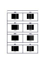
1.5 CONTROLLING THE SCANNER FROM THE POS SYSTEM<br />
The <strong>Pollux</strong> P-<strong>4010</strong> can be controlled from the POS system via the RS232C<br />
interface. Controlling is achieved by transmitting the following single byte commands<br />
to the <strong>scanner</strong>. In the <strong>Scantech</strong> default setting the following commands<br />
are available (more details upon request):<br />
ASCII <strong>code</strong><br />
function<br />
byte is also called:<br />
05 Hex<br />
power-up re-initialization<br />
ENQ or <br />
0E Hex<br />
0F Hex<br />
enable (cancels disable)<br />
disable<br />
Shift Out or <br />
Shift In or <br />
12 Hex sleep DC2 or <br />
14 Hex wake (cancels sleep) DC4 or <br />
When the <strong>scanner</strong> is disabled, the motor of the <strong>scanner</strong> will stay on until the<br />
<strong>scanner</strong> goes into sleep mode.
10 The <strong>Pollux</strong> P-<strong>4010</strong><br />
POS system<br />
Scanner control<br />
<strong>Pollux</strong> P-<strong>4010</strong><br />
POLLUX<br />
+12V dc<br />
- 12V dc<br />
+ 5V dc
Chapter 2<br />
Installing the <strong>Pollux</strong> P-<strong>4010</strong>
12 Installing the <strong>Pollux</strong> P-<strong>4010</strong><br />
Depending on the way you want to use the <strong>Pollux</strong> P-<strong>4010</strong>, the <strong>scanner</strong> can be<br />
installed fixed on a counter surface or sunk into the counter surface.<br />
The <strong>Pollux</strong> can be installed in two different ways, <strong>scanner</strong> housing Landscape<br />
or <strong>scanner</strong> housing Portrait (see the illustrations below). Refer to chapter 3 for<br />
the various mounting options of the <strong>Pollux</strong>.<br />
POLLUX<br />
POLLUX<br />
Cable supply<br />
Scanner Housing Landscape<br />
Scanner Housing Portrait<br />
Cable supply<br />
Independent from the installation you can direct the scan pattern in a way that<br />
suits your application most, thanks to the four directional optical assembly. For<br />
turning the optical assembly please refer to the <strong>Pollux</strong> Service Manual (authorized<br />
personnel only).<br />
90/180/270<br />
The turning of the optical assembly.<br />
POLLUX<br />
POLLUX<br />
Note:The orientation of the <strong>scanner</strong>’s optical<br />
assembly is factory assembled according to<br />
your preference!<br />
90/180/270<br />
IMPORTANT<br />
■ To make the instructions in this manual as clear as possible, the starting<br />
point for all instructions is the landscape <strong>scanner</strong> housing setup.
Installing the <strong>Pollux</strong> P-<strong>4010</strong> 13<br />
Instructions for installation on a counter surface are given in Section 2.1.<br />
Due to many POS systems on the market, a large number of communication<br />
cables is available. Make sure that you have the right cable to connect the <strong>scanner</strong><br />
to your POS or computer.<br />
NOTES<br />
■ The <strong>scanner</strong> and the host system must be switched off before starting the<br />
installation of the <strong>scanner</strong>. By following this precaution you prevent any<br />
electrical damage.<br />
■ You are advised to install the <strong>scanner</strong> in an air circulated place out of direct<br />
sunlight.<br />
2.1 INSTALLING THE SCANNER ON A COUNTER SURFACE<br />
Follow these steps to mount the <strong>scanner</strong> in a fixed counter surface position:<br />
1. Locate the optimal <strong>scanner</strong> position on the counter surface. Pay attention to<br />
the product flow, distance to the counter edge and convenience for the operator.<br />
2. Use the enclosed templates of the vertical mount to mark the places for the<br />
mounting holes at the counter surface and also the hole for the cable supply.<br />
You can also choose to lead the cables away on the counter surface by<br />
removing an insert in the back cover of the <strong>scanner</strong>.<br />
Note:<br />
- Use template A for installing the <strong>scanner</strong> housing landscape.<br />
- Use template B for installing the <strong>scanner</strong> housing portrait.<br />
3. Fasten the vertical mount to the surface with four screws (or four nuts and<br />
bolts) as illustrated in the figure.<br />
SCANNER FRONT
14 Installing the <strong>Pollux</strong> P-<strong>4010</strong><br />
4. Locate the small hole at the back cover of the <strong>scanner</strong>. Remove the back<br />
1. cover by pressing it with a coin as indicated in the figure.<br />
insert<br />
insert<br />
5. Lead the power supply cable and communication cable through the hole in<br />
the counter.<br />
6. Plug the communication cable with the 8 pin modular jack into Data port 1 if<br />
the host system features the RS232C or IBM RS485 interface, or into Data<br />
port 2 if the host system features the OCIA or KBW interface. Plug the other<br />
connector of the cable into the appropriate serial port of your POS or computer.<br />
Connect the <strong>Scantech</strong> universal power supply unit to the power supply<br />
port. Lead the cables through the <strong>scanner</strong> as illustrated in the figure on the<br />
next page.
Installing the <strong>Pollux</strong> P-<strong>4010</strong> 15<br />
INTERFACE INTERFACE POWER<br />
PORT 2 PORT AUX 1<br />
Interface port 1. Connect the communication<br />
cable to this port if the host system features<br />
the RS232C or IBM RS 485 interface<br />
INTERFACE POWER<br />
AUX PORT 2 INTERFACE PORT 1<br />
INTERFACE INTERFACE POWER<br />
PORT 2 PORT AUX 1<br />
Interface port 2. Connect the communication<br />
cable to this port if the host system features<br />
the OCIA or KBW interface
16 Installing the <strong>Pollux</strong> P-<strong>4010</strong><br />
7. Place the <strong>scanner</strong> on the vertical mount as illustrated in the figure.<br />
AUX INTERFACE INTERFACE POWER<br />
PORT 2 PORT 1<br />
SCANNER FRONT<br />
8. Reposition the back cover of the <strong>scanner</strong>.<br />
9. Power on the <strong>scanner</strong> by connecting the IEC power cord to the AC/DC power<br />
supply and plugging the AC power cord into an AC power outlet. Switch on<br />
the host system.<br />
IMPORTANT<br />
■ To activate Data port 2 (OCIA or KBW interface), follow this sequence:<br />
1. Plug in the appropriate interface cable and then power up the <strong>scanner</strong>.<br />
2. Scan the following <strong>code</strong>s from the Configuration Guide:<br />
- Open the <strong>scanner</strong> Programming Mode by scanning <strong>code</strong> 1.1<br />
- Return to factory default settings by scanning <strong>code</strong> 1.3<br />
Once the <strong>scanner</strong> is installed, you can start scanning bar <strong>code</strong> labels. If you<br />
want to change the default settings of the <strong>scanner</strong>, proceed to the Configuration<br />
Guide which came with the <strong>scanner</strong>.
Chapter 3<br />
Mounting options <strong>Pollux</strong> P-<strong>4010</strong>
18 Mounting options <strong>Pollux</strong> P-<strong>4010</strong><br />
The ability to turn the optical assembly of the <strong>Pollux</strong> provides a large number of<br />
mounting options. This chapter will help you find the best mounting option for<br />
your application. (For information on turning the optical assembly, please refer<br />
to the <strong>Pollux</strong> Service Manual. Authorized personnel only).<br />
The <strong>Pollux</strong> P-<strong>4010</strong> can be installed:<br />
- fixed on a counter surface or<br />
- sunk into the counter surface.<br />
Your choice depends on the way you intend to use the <strong>scanner</strong>.<br />
The following pages illustrate which mounting options are available.<br />
To install the <strong>Pollux</strong> in flyby mode for scanning from Right to Left, please refer to<br />
Section 3.1<br />
To install the <strong>Pollux</strong> in flyby mode for scanning from Left to Right, please refer to<br />
Section 3.2<br />
To install the <strong>Pollux</strong> in presentation mode, please refer to Section 3.3
Mounting options <strong>Pollux</strong> P-<strong>4010</strong> 19<br />
3.1 FLYBY MODE SCANNING: RIGHT TO LEFT<br />
To scan from Right to Left, install the <strong>scanner</strong> housing by:<br />
a. landscape orientation or<br />
b. portrait orientation.<br />
a. Scanning from Right to Left, <strong>scanner</strong> housing landscape orientation<br />
On counter surface<br />
3.1a1<br />
POLLUX<br />
special offer<br />
chewing-gum<br />
Cable supply<br />
Product flow
20 Mounting options <strong>Pollux</strong> P-<strong>4010</strong><br />
b. Scanning from Right to Left, <strong>scanner</strong> housing portrait orientation<br />
On counter surface<br />
3.1b1<br />
POLLUX<br />
special offer<br />
chewing-gum<br />
Cable supply<br />
Not recommended. The need to lift the products being scanned increases.<br />
Sunk into counter surface<br />
3.1b2<br />
POLLUX<br />
special offer<br />
chewing-gum<br />
Cable supply<br />
Product flow
Mounting options <strong>Pollux</strong> P-<strong>4010</strong> 21<br />
3.2 FLYBY MODE SCANNING: LEFT TO RIGHT<br />
To scan from Left to Right, install the <strong>scanner</strong> housing by:<br />
a. landscape orientation or<br />
b. portrait orientation.<br />
a. Scanning from Left to Right, <strong>scanner</strong> housing landscape orientation<br />
On counter surface<br />
3.2a1<br />
special offer<br />
chewing-gum<br />
POLLUX<br />
Product flow<br />
Cable supply
22 Mounting options <strong>Pollux</strong> P-<strong>4010</strong><br />
b. Scanning from Left to Right, <strong>scanner</strong> housing portrait orientation<br />
On counter surface<br />
3.2b1<br />
special offer<br />
chewing-gum<br />
POLLUX<br />
Cable supply<br />
Not recommended. The need to lift the products being scanned increases.<br />
Sunk into counter surface<br />
3.2b2<br />
POLLUX<br />
special offer<br />
chewing-gum<br />
Product flow<br />
Cable supply
POLLUX<br />
Mounting options <strong>Pollux</strong> P-<strong>4010</strong> 23<br />
3.3 PRESENTATION MODE SCANNING<br />
To scan in presentation mode, install the <strong>scanner</strong> housing by:<br />
a. landscape orientation or<br />
b. portrait orientation.<br />
a. Scanning in presentation mode, <strong>scanner</strong> housing landscape orientation<br />
On counter surface<br />
3.3a1<br />
Cable supply<br />
2<br />
1<br />
special offer<br />
chewing-gum<br />
Product flow<br />
Not recommended. Due to a minimized scan pattern.
POLLUX<br />
POLLUX<br />
24 Mounting options <strong>Pollux</strong> P-<strong>4010</strong><br />
b. Scanning in presentation mode, <strong>scanner</strong> housing portrait orientation<br />
On counter surface<br />
3.3b1<br />
special offer<br />
chewing-gum<br />
1<br />
2<br />
Product flow<br />
Cable supply<br />
Sunk into counter surface<br />
3.3b2<br />
special offer<br />
chewing-gum<br />
1<br />
2<br />
Product flow<br />
Cable supply<br />
Not recommended. Due to a minimized scan pattern.
Appendices<br />
A. Connector types and pin definitions<br />
B. Technical Specifications<br />
C. Troubleshooting
26 Appendices<br />
A. CONNECTOR TYPES AND PIN DEFINITIONS<br />
There are two dual interface versions of the <strong>Pollux</strong> available: RS232C/OCIA and<br />
IBM RS485/Keyboard Wedge. The various pin definitions for the applicable Data<br />
port are given on page 31. The connector to be used for the port is indicated<br />
below.<br />
AUX INTERFACE INTERFACE POWER<br />
PORT 2 PORT 1<br />
POWER SUPPLY PORT<br />
AUX PORT<br />
IINTERFACE PORT 1<br />
AMP 5-554169-1<br />
male connector<br />
pin 10 pin 1<br />
Stewart 940SP301010RK2<br />
male connector<br />
front view:<br />
;;;;;;;;<br />
;;;;;;;;<br />
pin 1<br />
;;;;;;;;<br />
;;;;;;;;<br />
pin 8<br />
pin 8 pin 1<br />
pin 1<br />
Aux port<br />
pin 10<br />
INTERFACE PORT 2<br />
Pin Description<br />
1 +5VDC (250 mA max.)<br />
2 CTS<br />
3 RXD<br />
4 Reserved<br />
5 RTS<br />
6 GND<br />
7-10 Reserved<br />
pin 8 pin 1<br />
AMP 5-554170-1<br />
male connector<br />
front view:<br />
pin 1<br />
;;;;;;;;<br />
;;;;;;;;<br />
pin 8<br />
IMPORTANT<br />
■ To activate Data port 2 (OCIA or KBW interface), follow this sequence:<br />
1. Plug in the appropriate interface cable and then power up the <strong>scanner</strong>.<br />
2. Scan the following <strong>code</strong>s from the Configuration Guide:<br />
- Open the <strong>scanner</strong> Programming Mode by scanning <strong>code</strong> 1.1<br />
- Return to factory default settings by scanning <strong>code</strong> 1.3
Appendices 27<br />
Pin definition for dual interface version RS232C-OCIA<br />
RS232C interface<br />
Data port 1<br />
OCIA interface<br />
Data port 2<br />
Pin<br />
Description<br />
Direction<br />
Pin<br />
Description<br />
Direction<br />
1<br />
CTS<br />
input<br />
1<br />
IFID<br />
input<br />
2<br />
RXD<br />
input<br />
2<br />
DATA<br />
output<br />
3<br />
TXD<br />
output<br />
3<br />
DATA RTN<br />
output<br />
4<br />
RTS<br />
output<br />
4<br />
CLOCK IN<br />
input<br />
5<br />
GND<br />
-<br />
5<br />
GND<br />
-<br />
6<br />
Not Con.<br />
-<br />
6<br />
CLOCK IN RTN<br />
input<br />
7<br />
8<br />
Reserved<br />
7<br />
8<br />
RESET<br />
RESET RTN<br />
input<br />
input<br />
Pin definition for dual interface version IBM RS485-Keyboard Wedge<br />
IBM RS485 interface<br />
Data port 1<br />
KBW interface<br />
Data port 2<br />
Pin<br />
Description<br />
Direction<br />
Pin<br />
Description<br />
Direction<br />
1<br />
Not Con.<br />
-<br />
1<br />
IFID1<br />
input<br />
2<br />
IO-A<br />
input/output<br />
2<br />
KB_DATA<br />
output<br />
3<br />
IO-B<br />
input/output<br />
3<br />
KB_CLCK<br />
output<br />
4<br />
Not Con.<br />
-<br />
4<br />
PC_DATA<br />
input<br />
5<br />
GND<br />
-<br />
5<br />
PC_GND<br />
-<br />
6<br />
Not Con.<br />
-<br />
6<br />
PC_CLCK<br />
input<br />
7<br />
8<br />
Reserved<br />
7<br />
8<br />
PC_5V<br />
IFID2<br />
input<br />
input
28 Appendices<br />
B. TECHNICAL SPECIFICATIONS<br />
Electrical<br />
Power supply voltage<br />
DC input to <strong>scanner</strong><br />
Interfaces<br />
Auxiliary port<br />
100 - 250 V ac, 50/60 Hz<br />
+ 12 V dc, 600 mA<br />
- 12 V dc, 75 mA<br />
+ 5 V dc, 350 mA<br />
Depending on <strong>scanner</strong> version<br />
Interface port 1: RS232 or IBM RS485<br />
Interface port 2: OCIA or KBW<br />
Secondary <strong>scanner</strong> (250 mA max.)<br />
Optical<br />
Light source<br />
Depth of field<br />
Scan pattern<br />
Scan rate<br />
Visible <strong>laser</strong> diode (650 nm)<br />
300 mm<br />
5 directions scan field, 20 lines scan pattern<br />
2000 scans / second<br />
Decoding<br />
<strong>Bar</strong> <strong>code</strong> types<br />
EAN/UPC/JAN + Add-on<br />
Code 128, EAN 128, Code 39, Code 32, Codabar, ITF<br />
Physical<br />
Weight<br />
Dimensions<br />
210 mm<br />
1,2 kg<br />
L x W x D: 183 x 210 x 70 mm<br />
: 7.2 x 8.25 x 2.75 inch<br />
70 mm<br />
70 mm<br />
POLLUX<br />
183 mm
Appendices 29<br />
Environmental<br />
Operating temperature<br />
Humidity<br />
0° C ~ 40° C<br />
0% ~ 95% RH (non-condensing)<br />
Safety<br />
Laser safety<br />
IEC 825-1 (1993) Class I, U.S. 21CFR1040 Class IIa<br />
Electrical safety<br />
EN 60950 second edition<br />
UL1950 (third edition), c-UL (according CSA22.2.950-95)<br />
Flammability rate 94V-0<br />
EM Compatibility<br />
Radio and TV interference EN 55022 Class B (1994), FCC part 15 Class A (1992)<br />
Harmonic current emissions EN 61000-3-2 (1995)<br />
EM-immunity<br />
EN 50082-1 (1992) based on:<br />
ElectroStatic Discharge (ESD) IEC 801-2 (1991)<br />
Radio frequency immunity IEC 801-3 (1984) / ENV 50140 (1993)<br />
Electrical fast transient IEC 801-4 (1988)
30 Appendices<br />
C. TROUBLESHOOTING<br />
This section contains information on solving problems you may encounter when<br />
using the <strong>scanner</strong>. If troubles occur, take a moment to read the information in<br />
this section. However, before referring to the diagnostic tips make sure that the<br />
<strong>scanner</strong> is installed as described in Chapter 2 and that all cables are properly<br />
connected.
Appendices 31<br />
Problem<br />
The <strong>scanner</strong> is on but a bar <strong>code</strong> cannot<br />
be read. The LED is red.<br />
Diagnostic Tips<br />
■ The <strong>scanner</strong> window is dirty. Clean the<br />
■ <strong>scanner</strong> window as described in the<br />
■ Maintenance section.<br />
■ The presented bar <strong>code</strong> type is not<br />
■ enabled. Select the bar <strong>code</strong> type with<br />
■ the Configuration Guide.<br />
■ The <strong>scanner</strong> is disabled by the host.<br />
■ Refer to Section 1.5.<br />
■ The bar <strong>code</strong> type you presented to the<br />
■ <strong>scanner</strong> is not supported by the <strong>Pollux</strong>.<br />
■ The <strong>scanner</strong> is in Slave Mode. Press the<br />
Sleep Mode button for at least 3 seconds<br />
to enter Programming Mode and Return to<br />
Default by scanning <strong>code</strong> "1.3" out of<br />
"Configuration Guide" booklet.<br />
The <strong>scanner</strong> is on, but the motor is not<br />
rotating. A bar <strong>code</strong> cannot be read.<br />
The LED is intermittently flashing red.<br />
The LED is alternating red/green.<br />
The LED is alternating red/green and<br />
beeps are heard.<br />
The <strong>scanner</strong> does not accept more than<br />
two or three bar <strong>code</strong>s.<br />
The LED is red and green.<br />
The LED is blinking red and green.<br />
■ The <strong>scanner</strong> is in sleep mode. Press the<br />
switch on top of the <strong>scanner</strong> to reactivate<br />
the <strong>scanner</strong> (or use the wake protocol.<br />
Refer to section 1.5).<br />
■ Mirror motor is defective and must be<br />
replaced (Authorized personnel only).<br />
■ Possible failure of the scanning safeguard<br />
circuit. Immediately disconnect the <strong>scanner</strong><br />
from its power source. Contact your<br />
supplier.<br />
■ There is no proper handshaking with the<br />
host system. Switch the host system on<br />
and check connection and communication<br />
settings.<br />
■ The <strong>laser</strong> is not functioning. The <strong>laser</strong> is<br />
defect. Contact your supplier.<br />
■ The ambient temperature is too high. Make<br />
sure the <strong>scanner</strong> has enough air ventilation<br />
and is not placed in direct sunlight.
32 Appendices<br />
Problem<br />
Diagnostic Tips<br />
The LED remains green.<br />
■ The <strong>scanner</strong> is continuously seeing a bar<br />
<strong>code</strong>. Remove all bar <strong>code</strong> labels from the<br />
scan volume of the <strong>scanner</strong> and try again.<br />
■ The <strong>scanner</strong> cannot send the data to the<br />
host system. There is no proper<br />
handshaking between the <strong>scanner</strong> and the<br />
host. Scanner buffer is full. Make sure that<br />
all cables are connected and your host<br />
system is ready to receive data.<br />
A bar <strong>code</strong> is read by the <strong>scanner</strong> but<br />
not accepted by the host system.<br />
■ The communication cable is not connected<br />
to the serial port of your host system.<br />
Refer to the manual of your host system<br />
to locate the serial port.<br />
■ The communication settings of the host<br />
and <strong>scanner</strong> do not match. Ensure that the<br />
setting value for both devices are the same.<br />
For proper adjustment values see the<br />
Configuration Guide.<br />
■ The communication cable does not suit<br />
your host system. Contact your supplier for<br />
the correct communication cable.<br />
■ The data format is not supported by the<br />
software running on the host system.
Hole in counter<br />
surface for<br />
cable supply<br />
Scanner outline<br />
SCANNER FRONT<br />
SCANNER FRONT<br />
TEMPLATE A: SCANNER HOUSING LANDSCAPE<br />
Scanner outline<br />
TEMPLATE B: SCANNER HOUSING PORTRAIT<br />
Hole in counter<br />
surface for<br />
cable supply
<strong>Scantech</strong>-ID BV<br />
Amersfoortsestraat 124<br />
3769 AN Soesterberg<br />
The Netherlands<br />
Phone: +31 (0 )33 469 84 00<br />
Fax: +31 (0 )33 465 06 15<br />
E-mail: info@scantech-id.com<br />
Internet: www.scantech-id.com