Air Tube Disc Clutches and Brakes - Arten Freios e Embreagens ...
Air Tube Disc Clutches and Brakes - Arten Freios e Embreagens ...
Air Tube Disc Clutches and Brakes - Arten Freios e Embreagens ...

You also want an ePaper? Increase the reach of your titles
YUMPU automatically turns print PDFs into web optimized ePapers that Google loves.
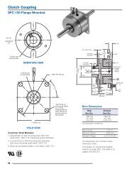
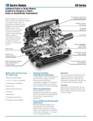
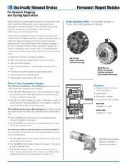
<strong>Air</strong> <strong>Tube</strong> <strong>Disc</strong> <strong>Clutches</strong> <strong>and</strong> <strong>Brakes</strong><br />
Wichita <strong>Air</strong> <strong>Tube</strong> <strong>Disc</strong> <strong>Clutches</strong> <strong>and</strong> <strong>Brakes</strong><br />
provide the high speed acceleration <strong>and</strong><br />
deceleration essential for today’s process<br />
equipment. The low-inertia designs reduce<br />
power consumption <strong>and</strong> heat build-up in<br />
cycling applications. A quick energizing<br />
air-tube provides fast response with smooth<br />
engagement.<br />
Low Inertia <strong>and</strong> Very Low Inertia<br />
clutches <strong>and</strong> brakes<br />
High-torque clutches<br />
Spring-Set air<br />
release brakes<br />
28
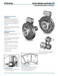
Clutch <strong>and</strong> brake combinations<br />
4 Clutch combinations<br />
Low inertia<br />
Very low inertia<br />
Low inertia high torque<br />
Very low inertia high torque<br />
4 Brake combinations<br />
Low inertia<br />
Very low inertia<br />
Low inertia spring-set<br />
Very low inertia spring-set<br />
Clutch<br />
A<br />
B<br />
Low inertia<br />
C<br />
Brake<br />
D<br />
Ring with demountable<br />
backplate <strong>and</strong> hub<br />
E<br />
High torque clutch<br />
F<br />
• Ring with demountable<br />
backplate can be used with<br />
any of the actuators shown.<br />
• Hub can be used with either<br />
the Very Low Inertia or the Low<br />
Inertia center plates <strong>and</strong><br />
friction discs.<br />
• Very Low Inertia design utilizes<br />
thick segmented friction discs<br />
which increases friction disc life<br />
<strong>and</strong> heat dissipation.<br />
Very low inertia<br />
Drive plate assembly<br />
Available with bonded or<br />
riveted friction pads<br />
Spring-Set brake<br />
G<br />
H<br />
<strong>Air</strong> <strong>Tube</strong> Plate<br />
(function) Assembly<br />
29
<strong>Air</strong> <strong>Tube</strong> <strong>Disc</strong> <strong>Clutches</strong> <strong>and</strong> <strong>Brakes</strong><br />
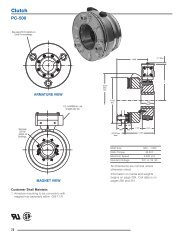
Typical Applications<br />
Wichita High Torque<br />
Clutch provides fast<br />
acceleration <strong>and</strong> long<br />
life on metal forming<br />
punch presses.<br />
Clutch Gear<br />
ATD 114 Spring-Set<br />
<strong>Air</strong> Release Brake<br />
1/2" NPT Hole<br />
1" 14 NF Tap<br />
Grease<br />
Relief<br />
Grease Seal<br />
1/2" NPT<br />
Grease Fitting<br />
1/2" NPT, 3 Spuds<br />
Typical Wichita<br />
clutch <strong>and</strong> brake<br />
mounting on a<br />
press.<br />
Wichita Low Inertia <strong>Brakes</strong> increase tension<br />
control for paper unwind st<strong>and</strong>s.<br />
Wichita Spring-Set<br />
<strong>Air</strong> Release <strong>Brakes</strong><br />
insure accuracy <strong>and</strong><br />
high performance for<br />
a metal shear.<br />
30
Application Factors<br />
Clutch sizes are affected by the<br />
following variables:<br />
1. Machines that operate under<br />
smooth loads require smaller<br />
clutches. These machines are<br />
driven by either multi-cylinder high<br />
speed engines or electric motors<br />
with reduced starting current.<br />
2. Drives that require high starting<br />
current motors will require clutches<br />
with sufficient torque to prevent<br />
excessive slipping while starting.<br />
3. Starting torque may be high,<br />
which requires a fast clutch<br />
response time to transmit the<br />
required torque or extended<br />
clutch slip time is required to<br />
protect the prime mover.<br />
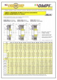
Application Guidelines<br />
This chart gives application factors<br />
ranging from light duty (the A group)<br />
to extra heavy duty (the D group).<br />
After initial usage is determined, see<br />
Field of Application Group A Group B Group C Group D<br />
Pumps Centrifugal Reciprocating compressors Reciprocating compressors<br />
compressors over 2 cylinders, one or two cylinders<br />
centrifugal fans & blowers<br />
Agitators Liquid Semi-solid Solids<br />
Brick<br />
Brick press, extruder, pug mill<br />
manufacturing<br />
Canning & bottling machine<br />
4. Starting torques may be very low<br />
compared to the normal torque,<br />
which may result in the clutch not<br />
being fully pressurized prior to the<br />
time of full torque requirement. This<br />
will cause the clutch to overheat<br />
from slippage. Clutch inflation time<br />
in this instance is very important.<br />
5. <strong>Clutches</strong> on most machines are<br />
designed to slip prior to damage<br />
from shockloads. As a result, the<br />
clutch may require periodic<br />
maintenance; therefore, the<br />
clutch should be located for easy<br />
access in the power train.<br />
<strong>Clutches</strong> should also be located<br />
for maximum cooling air. In<br />
“Selection Requirements” to complete<br />
the selection process. The inflation <strong>and</strong><br />
exhaust time should also be checked<br />
to insure proper response.<br />
Bottle-can feeders, filling, mixers<br />
instances where this is not possible,<br />
forced air cooling may be<br />
necessary for extended clutch life.<br />
6. Safe clutch operating speeds<br />
should be maintained in product<br />
design.<br />
Maximum Clutch Contact Velocity<br />
FPM<br />
Material<br />
6,000 (Recommended cast iron<br />
9,000 upper limit for slip) ductile iron<br />
12,000 steel<br />
Dynamic balancing recommended<br />
when peripheral speeds exceed<br />
3500 fpm. The maximum speeds<br />
shown are safe operating speeds<br />
based on years of Wichita testing.<br />
Please do not exceed these limits.<br />
Engine driven equipment Crane, hoist, engine Crowd<br />
Grinding mills Ball-rod-sag-pebble Crushers, shakers<br />
Lumber processing Yarder Carriages, conveyers Chipper, logger<br />
Marine Propulsion clutch CP wheel Shaft brakes, propulsion<br />
reversing type, anchor winch<br />
Bulk material Conveyors evenly loaded, Feeders Elevators<br />
h<strong>and</strong>ling<br />
line shaft evenly loaded<br />
Metal production & Coilers, slitters, press brake, Draw bench, rolling mill, Hammer mill, forming<br />
metalforming non-geared press, geared press shear, back geared press, press, forging press,<br />
deep draw press, transfer header press, knuckle press<br />
press, toggle press<br />
Paper industry dryer Fourdrinier to 500 FPM, Fourdrinier to 1800 RPM<br />
sections & calenders paper mill plane & press selections, calenders<br />
Consult factory smoothing press & dryers<br />
Petroleum Drilling & service rig master Mud pumps,<br />
production clutches, compound clutches, PTO clutches<br />
rotary, drum<br />
Rubber Transfer machines Banberry mixer, drum mixer, Centrifuge<br />
manufacturing evenly loaded extruder, calender<br />
A<br />
B<br />
C<br />
D<br />
E<br />
F<br />
G<br />
H<br />
31
<strong>Air</strong> <strong>Tube</strong> <strong>Disc</strong> <strong>Clutches</strong> <strong>and</strong> <strong>Brakes</strong><br />
Low Inertia <strong>and</strong> Very Low Inertia <strong>Clutches</strong> <strong>and</strong> <strong>Brakes</strong><br />
Ring<br />
Shims<br />
Multiple Spud<br />
<strong>Air</strong>tube<br />
Very Low Inertia<br />
Drive Plate Assembly<br />
with Bonded or<br />
Riveted Pads<br />
Floating Plate<br />
Pressure<br />
Plate<br />
<strong>Air</strong>tube<br />
Holding<br />
Plate<br />
Hub<br />
Ductile<br />
Center Plate<br />
Grooved<br />
Friction <strong>Disc</strong><br />
Demountable<br />
Backplate<br />
Roto-Coupling<br />
Spider<br />
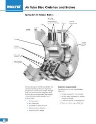
Operating Features<br />
The Wichita <strong>Air</strong>-<strong>Tube</strong> <strong>Disc</strong> Clutch combines<br />
all the best features of the disc type clutch<br />
with all the advantages of direct air<br />
engagement. The simplest <strong>and</strong> most<br />
trouble-free method of applying air<br />
pressure is through direct axial pressure<br />
application by compressed air in a special<br />
composition full-circle tube.<br />
Wichita <strong>Clutches</strong> engage smoothly without<br />
noise, shock or impact <strong>and</strong> release completely<br />
in a fraction of a second. Extremely<br />
fast action is possible because of the small<br />
volume of air required.<br />
<strong>Clutches</strong> may be slipped moderately to<br />
control the acceleration rate.<br />
When large inertia loads are powered from<br />
electric motors, smooth, controlled slip starts<br />
by Wichita <strong>Clutches</strong> can keep power<br />
dem<strong>and</strong>s below the allowed maximum.<br />
Heat generated by controlled slipping or<br />
high cycle rate operation is dissipated by<br />
the centrifugal blower design of these units.<br />
Wichita Low Inertia <strong>and</strong> Very Low Inertia<br />
<strong>Clutches</strong> <strong>and</strong> <strong>Brakes</strong> are designed to be<br />
completely free from effects of centrifugal<br />
force <strong>and</strong> self energization.<br />
Torque developed is in direct proportion to<br />
air pressure applied.<br />
These clutches <strong>and</strong> brakes interface well<br />
with automated controls through simple air<br />
<strong>and</strong>/or electric circuits.<br />
Water cooled, copper disc clutches are<br />
available for use when power transmission<br />
needs require excessive or constant<br />
slipping which dem<strong>and</strong>s higher heat<br />
dissipation.<br />
Wichita <strong>Clutches</strong> operate perfectly when<br />
teamed with Wichita <strong>Brakes</strong> in production<br />
situations requiring tension control, cyclic<br />
duty, or positioning.<br />
Wichita <strong>Brakes</strong> have the same outst<strong>and</strong>ing<br />
performance characteristics as Wichita<br />
<strong>Clutches</strong>.<br />
32
Selection Requirements<br />
The selection of a Low Inertia Brake is<br />
based on:<br />
1. Torque required to stop a load.<br />
2. Friction area necessary to absorb<br />
rotational energy.<br />
3. Contact velocity of rotating discs.<br />
4. Maximum bore capacity of unit.<br />
Selection example<br />
To properly select a Low Inertia Brake for<br />
a controlled deceleration application, the<br />
following information is needed:<br />
Speed . . . . . . . . . . . . . . . . . 750 rpm<br />
Shaft Dia. . . . . . . . . . . . . . . 5 In.<br />
Inertia to Stop . . . . . . . . . . . 2,473 lb.ft. 2<br />
Stop Time . . . . . . . . . . . . . . 5 Sec.<br />
<strong>Air</strong> Pressure Available . . . . . 80 psi<br />
Calculations<br />
Avg. hp = WR 2 X (rpm) 2<br />
3.2 x 10 6 x Stop Time<br />
= 2,473 X (750) 2<br />
3.2 x 10 6 x 5 Sec. = 87 HP<br />
Swept<br />
Avg. hp<br />
Friction = hp absorption rate for 5 seconds<br />
Area (see page 160)<br />
= 87 hp = 202 in. 2<br />
0.43<br />
Torque = WR 2 x rpm<br />
25.5 x Stop Time<br />
= 2.473 x 750<br />
25.5 x 5<br />
= 14,547 lb.in.<br />
Using the above calculations, consult the<br />
Low Inertia Specifications Chart on<br />
pages 34 <strong>and</strong> 35.<br />
Summary<br />
As calculated, the torque required to stop<br />
the load in 5 seconds is 14,547 lb.in. Wichita<br />
Low Inertia <strong>Brakes</strong> are rated at 100 psi. This<br />
application has only 80 psi available.<br />
To determine the torque rating of a Low<br />
Inertia brake at 80 psi apply the following<br />
formula:<br />
Application: Torque for a Low Inertia Brake<br />
= Torque X Catalog Rated Pressure<br />
Available <strong>Air</strong> Pressure<br />
= 14,547 X<br />
100<br />
= 18,183 lb.in.<br />
80<br />
Consult pages 34 <strong>and</strong> 35 for clutch <strong>and</strong><br />
brake specifications. A Low Inertia model<br />
114 Brake produces 27,625 lb.in. torque at<br />
100 psi. However, the bore capacity is<br />
4.125 inches. This application requires<br />
a 5 in. bore. Therefore, a Low Inertia 118<br />
is to be investigated.<br />
Catalog Torque Rating = 64,500 lb.in<br />
@ 100 psi<br />
Maximum Bore Capacity = 5.25 in.<br />
Catalog Swept Friction Area = 264 in. 2<br />
Calculations show this application needs at<br />
least 202 In. 2 to absorb the heat.<br />
All of these ratings are acceptable for the<br />
given application data.<br />
Next, check contact velocity of rotating<br />
discs.<br />
= Diameter of centerplate X rpm<br />
3.82<br />
= 18" X 750<br />
3.82<br />
= 3,534 fpm<br />
St<strong>and</strong>ard material is sufficient up to 6,000<br />
fpm (see page 31). Balancing is<br />
recommended above 3,500 fpm.<br />
Therefore, a Low Inertia ATD-118 brake is<br />
the optimum choice for this application.<br />
A Spring-Set <strong>Air</strong> Release Brake is also<br />
available (see page 54).<br />
Note:<br />
This application example is for preliminary<br />
sizing only. Contact a Wichita Sales Engineer<br />
or the factory for final selection.<br />
A<br />
B<br />
C<br />
D<br />
E<br />
F<br />
G<br />
H<br />
33
<strong>Air</strong> <strong>Tube</strong> <strong>Disc</strong> <strong>Clutches</strong> <strong>and</strong> <strong>Brakes</strong><br />
Low Inertia <strong>and</strong> Very Low Inertia <strong>Clutches</strong> <strong>and</strong> <strong>Brakes</strong><br />
Specifications<br />
Slip<br />
Maximum<br />
Max<br />
Torque<br />
Horsepower<br />
Bore<br />
Model Lb. in at Per 100 RPM<br />
Rect. Recommended Swept<br />
Size 100 PSI* Duty<br />
Key Clearances Friction<br />
ATD- .3 CF A B C D Inches Inches Area-In 2<br />
106 3,950 6.2 4.4 2.2 1.1 2 1/16-3/32 39<br />
206 7,900 12.5 8.8 4.4 2.2 2 1/16-3/32 78<br />
108 7,000 11.1 8 4 2 2-3/8 1/16-1/8 56<br />
208 14,000 22.2 16 8 4 2-3/8 3/32-5/32 112<br />
111 15,900 25 18 9 5 2-5/8 1/16-1/8 114<br />
211 31,800 50 36 18 10 2-5/8 3/32-5/32 228<br />
114 27,625 44 31 16 8 4-1/8 1/16-1/8 158<br />
214 55,250 88 62 32 16 4-1/8 3/32-5/32 316<br />
118 64,500 102 75 35 21 5-1/4 1/16-1/8 264<br />
218 129,000 204 150 70 42 5-1/4 3/32-5/32 528<br />
124H 153,700 243 180 90 40 7 3/32-5/32 574<br />
224H 307,400 487 360 180 80 7 1/8-3/16 1,148<br />
130H 327,000 519 380 190 100 8-1/2 3/32-5/32 827<br />
230H 654,000 1038 760 380 200 8-1/2 1/8-3/16 1,654<br />
136 508,000 805 600 295 165 10-1/2 3/32-5/32 1,150<br />
236 1,016,000 1610 1200 590 330 10-1/2 1/8-3/16 2,300<br />
142 726,000 1150 850 425 235 14 1/8-3/16 1,400<br />
242 1,452,800 2300 1700 850 470 14 5/32-7/32 2,800<br />
148 1,402,500 2225 1600 800 455 18 1/8-3/16 2,010<br />
248 2,805,000 4450 3200 1600 915 18 5/32-7/32 4,020<br />
260 5,950,000 9440 5950 3470 1940 19 3/16-5/16 7,230<br />
360 8,925,000 14160 8925 5205 2910 19 1/4-3/8 10,845<br />
*Max. recommended air pressure – 130 PSI.<br />
Model No.<br />
Model<br />
Size<br />
ATD-xxx<br />
ATD-xxx<br />
ATD-xxx<br />
ATD-xxx<br />
Model<br />
Type<br />
LIC for Low Inertia Clutch<br />
LIB for Low Inertia Brake<br />
VLIC for Very Low Inertia Clutch<br />
VLIB for Very Low Inertia Brake<br />
Note: Very Low Inertia <strong>Clutches</strong> <strong>and</strong> <strong>Brakes</strong> are available<br />
in sizes from ATD-108 to ATD-224H.<br />
34
A<br />
Low Inertia <strong>Clutches</strong><br />
Low Inertia <strong>Brakes</strong><br />
HUB<br />
HUB<br />
Model Total Total HUB & CP Effec. Total HUB & CP Effect.<br />
Size Wt. WR 2 & CP WR 2 Wt.† Wt. & CP WR 2 Wt.†<br />
ATD- Lbs. #Ft. 2 Wt. Lbs. #Ft. 2 Lbs. Lbs. Wt. Lbs. #Ft. 2 Lbs.<br />
106 27.5 2.5 6.40 .24 5.67 25.5 6.40 .24 5.67<br />
206 40.5 3.3 12.17 .46 10.01 38.5 12.17 .46 10.01<br />
108 48.73 6.15 10.0 .55 8.50 46.23 10.0 .55 8.50<br />
208 53.0 6.87 16.0 .72 11.0 50.5 16.0 .72 11.0<br />
111 79.21 15.63 15.0 1.35 15.0 75.21 15.0 1.35 15.0<br />
211 118.25 22.92 30.0 2.6 23.3 114.25 30.0 2.6 23.3<br />
114 127 45 48 5.6 28.5 124 48 5.6 28.5<br />
214 178 59 65 11 51.5 175 65 11 51.5<br />
118 201 83 71 14.5 58 194 71 14.5 58<br />
218 323 146 113 27.6 102 316 113 27.6 102<br />
124H 504 399 131 50 120 496 131 50 120<br />
224H 680 498 260 101 225 875 260 101 225<br />
130H 685 922 212 129 178 643 212 129 178<br />
230H 1146 1216 402 244 358 1004 402 244 358<br />
136 1209 1842 351 325 364 1049 351 325 364<br />
236 1822 2667 784 705 681 1642 784 705 681<br />
142 1967 4721 680 705 438 1907 680 705 438<br />
242 2732 5750 1197 1385 852 2528 1197 1385 852<br />
148 3158 9325 1101 1785 779 3078 1101 1785 779<br />
248 4700 13775 1942 3335 1465 4620 1942 3335 1465<br />
260 9453 48733 2567 7077 3011 9261 2567 7077 3011<br />
360 11643 57286 3870 10615 4373 11451 3870 10615 4373<br />
Very Low Inertia <strong>Clutches</strong><br />
Very Low Inertia <strong>Brakes</strong><br />
HUB<br />
HUB<br />
Model Total Total HUB & DP Effec. Total HUB & DP Effect.<br />
Size Wt. WR 2 & DP WR 2 Wt.† Wt. & DP WR 2 Wt.†<br />
ATD- Lbs. #Ft. 2 Wt. Lbs. #Ft. 2 Lbs. Lbs. Wt. Lbs. #Ft. 2 Lbs.<br />
108 47.15 6.06 6.7 .24 11.53 44.85 6.7 .24 11.53<br />
208 65.16 8.17 12.9 .44 19.06 62.66 12.9 .44 19.06<br />
111 79.8 15.99 9.6 .59 21.8 75.8 9.6 .59 21.8<br />
211 115.5 23.47 18.6 1.15 40.6 111.55 18.6 1.15 40.6<br />
114 126 37.4 20.4 2.25 31.5 123 20.4 2.25 31.5<br />
214 180 56.2 39.8 4.44 58.5 177 39.8 4.44 58.5<br />
118 195.4 75.5 40.0 7.7 64 188.4 40.0 7.7 64<br />
218 299.6 141.4 75.0 14.7 120 292.6 75.0 14.7 120<br />
124H 471.5 377 84.0 28.5 155 463.5 84.0 28.5 155<br />
224H 632 551 150 54.9 197 624 150 54.9 197<br />
B<br />
C<br />
D<br />
E<br />
F<br />
G<br />
H<br />
35
<strong>Air</strong> <strong>Tube</strong> <strong>Disc</strong> <strong>Clutches</strong> <strong>and</strong> <strong>Brakes</strong><br />
<strong>Air</strong> system data<br />
PSI pressure<br />
Inflation<br />
Clutch air pressure during inflation<br />
can be closely estimated by the<br />
following:<br />
Clutch pressure<br />
Exhaust<br />
Clutch air pressure during exhaust<br />
can be closely estimated by the<br />
following:<br />
Clutch pressure<br />
Overlap<br />
A typical clutch-brake torque curve<br />
for a single backshaft press (cyclic<br />
application) would appear as<br />
shown below.<br />
Clutch<br />
psi<br />
t o<br />
t d<br />
t 1<br />
time<br />
psi<br />
t o<br />
t d<br />
t e<br />
time<br />
Torque (lb-in)<br />
t 2<br />
Brake<br />
t 1<br />
=<br />
( — ) 1 u — = Time to 95% full inflation<br />
3<br />
sec.<br />
K<br />
T overlap<br />
t OC t CC t 1C t OB t BC t 1B<br />
Clutch pressure = P 1 ( 1 – 1<br />
) psi<br />
e<br />
(inflation)<br />
Ktu<br />
This equation is accurate from 5% up<br />
to 95% P 1<br />
.<br />
P 1<br />
= Line pressure to clutch psi<br />
K <strong>and</strong> U = coefficients for specific<br />
clutch <strong>and</strong> air pressure<br />
from Specification Table<br />
e<br />
t o<br />
t d<br />
To clutch<br />
brake<br />
To clutch<br />
brake<br />
To clutch<br />
brake<br />
= Naperian base log<br />
= Time at initiation of signal for<br />
inflation sec.<br />
= Time delay of air system – sec.<br />
Flow<br />
control<br />
Free flow<br />
Flow<br />
control<br />
Free flow<br />
Modulating valve<br />
On off valve<br />
Exhaust<br />
Exhaust<br />
3 way solenoid valve<br />
Quick release<br />
valve<br />
Roto-coupling<br />
Volume tank<br />
Clutch pressure = (P 1<br />
) (R) (E-t) v psi<br />
(exhaust)<br />
R, E <strong>and</strong> V = coefficients for specific<br />
clutch <strong>and</strong> air pressure<br />
from Specification Table.<br />
t e<br />
t<br />
= Time to exhaust = E from Specification<br />
Table.<br />
= Time variable – seconds. In the<br />
exhaust equation “t” cannot<br />
exceed the value of “E” sec.<br />
Shown are some of the air systems used<br />
on Wichita clutches. These systems are<br />
acceptable for remote operation<br />
where clutch reaction time is not<br />
important. Faster clutch reaction time<br />
is accomplished as indicated in the<br />
diagram by locating the<br />
Regulator<br />
<strong>Air</strong><br />
supply<br />
flow control valve, if required,<br />
<strong>and</strong> the solenoid<br />
valve as close as possible<br />
to the roto-coupling.<br />
Where clutches are located on long<br />
shafts, the use of quick release valves<br />
on the clutch will facilitate faster<br />
clutch response.<br />
Clutch<br />
Time (sec.)<br />
t Oc = time at which disengaged<br />
clutch receives signal<br />
t Cc = time of clutch engagement<br />
t 1c = time of clutch full inflation<br />
t OB = time at which disengaged<br />
brake receives signal<br />
t Bc = time of brake engagement<br />
t 1B = time of brake full exhaust<br />
t 2<br />
Quick release<br />
valve<br />
= overlap time at which clutch<br />
<strong>and</strong> brake are both engaged<br />
Brake<br />
Flexible<br />
line<br />
Exhaust<br />
Flow control<br />
valve<br />
3 way<br />
solenoid valve<br />
Volume tank<br />
Regulator<br />
<strong>Air</strong><br />
supply<br />
Flexible<br />
line<br />
Exhaust<br />
Flow control<br />
valve<br />
3 way<br />
solenoid valve<br />
Volume tank<br />
Regulator<br />
<strong>Air</strong><br />
supply<br />
36
Low Inertia <strong>and</strong> Very Low Inertia <strong>Clutches</strong> <strong>and</strong> <strong>Brakes</strong><br />
Inflation Coefficients<br />
A<br />
Model<br />
Inflation Coefficients Operating <strong>Air</strong> Pressure<br />
Size 50 PSI 75 PSI 100 PSI<br />
ATD- K U K U K U<br />
108 15,800 2.2 7,100 2 265 1.2<br />
208 15,800 2.2 7,100 2 265 1.2<br />
111 890 1.7 880 1.6 5,100 2.2<br />
211 890 1.7 880 1.6 5,100 2.2<br />
114 980 2.3 980 2.3 980 2.3<br />
214 980 2.3 980 2.3 980 2.3<br />
118 9,600 3.1 1,560 2.4 9,600 3.1<br />
218 9,600 3.1 1,560 2.4 9,600 3.1<br />
124H 145 1.8 90 1.6 87 1.6<br />
224H 145 1.8 90 1.6 87 1.6<br />
130H 185 2 150 2 93 1.8<br />
230H 185 2 150 2 93 1.8<br />
136 170 2 250 2.2 160 2<br />
236 170 2 250 2.2 160 2<br />
142 115 2 125 2 111 2<br />
242 115 2 125 2 111 2<br />
148 25 1.6 22 1.6 26 1.8<br />
248 25 1.6 22 1.6 26 1.8<br />
260 28 1.8 22 1.8 20 1.8<br />
360 28 1.8 22 1.8 20 1.8<br />
Exhaust Coefficients<br />
Model<br />
Exhaust Coefficients Operating <strong>Air</strong> Pressure<br />
Size 50 PSI 75 PSI 100 PSI<br />
ATD- R E V R E V R E V<br />
108 60 .016 1.0 525 .02 1.6 240 .02 1.4<br />
208 60 .016 1.0 525 .02 1.6 240 .02 1.4<br />
111 1,000 .032 2 8,200 .04 2.8 4,930 .048 2.8<br />
211 1,000 .032 2 8,200 .04 2.8 4,930 .048 2.8<br />
114 720 .072 2.5 800 .069 2.5 1,840 .082 3<br />
214 720 .072 2.5 800 .069 2.5 1,840 .082 3<br />
118 44 .068 1.4 40 .072 1.4 34 .08 1.4<br />
218 44 .068 1.4 40 .072 1.4 34 .08 1.4<br />
124H 360 .096 2.5 240 .112 2.5 270 .136 2.8<br />
224H 360 .096 2.5 240 .112 2.5 270 .136 2.8<br />
130H 120 .104 2.1 140 .128 2.4 146 .158 2.7<br />
230H 120 .104 2.1 140 .128 2.4 146 .158 2.7<br />
136 124 .112 2.2 92 .128 2.2 76 .152 2.3<br />
236 124 .112 2.2 92 .128 2.2 76 .152 2.3<br />
142 132 .12 2.3 89 .144 2.3 61 .168 2.3<br />
242 132 .12 2.3 89 .144 2.3 61 .168 2.3<br />
148 20 .224 2 20 .256 2.2 19 .308 2.5<br />
248 20 .224 2 20 .256 2.2 19 .308 2.5<br />
260 24 .264 2.4 10 .367 2.3 9.9 .352 2.2<br />
360 24 .264 2.4 10 .367 2.3 9.9 .352 2.2<br />
B<br />
C<br />
D<br />
E<br />
F<br />
G<br />
H<br />
Note: Very Low Inertia <strong>Clutches</strong> <strong>and</strong> <strong>Brakes</strong> are available in sizes from ATD-108 to ATD-224H. See page 34.<br />
37
<strong>Air</strong> <strong>Tube</strong> <strong>Disc</strong> <strong>Clutches</strong> <strong>and</strong> <strong>Brakes</strong><br />
Low Inertia <strong>and</strong> Very Low Inertia <strong>Clutches</strong> <strong>and</strong> <strong>Brakes</strong><br />
Demountable backplate<br />
A<br />
a - Number of holes<br />
b - Hole size<br />
B<br />
C<br />
D<br />
H<br />
I<br />
J<br />
Z<br />
j<br />
Clutch or brake<br />
k<br />
L<br />
K<br />
O<br />
e<br />
(See<br />
Note 1)<br />
Low inertia Very low inertia<br />
Dimensions (in)<br />
(Consult factory for drawing before final layout.)<br />
Model<br />
Size ATD- A B C D E F G H I J K L<br />
106 8.75 8.000 7.377/7.379 4.19 .06 .562 .69 7.373/7.375 8.000 7.377/7.379 — —<br />
206 8.75 8.000 7.377/7.379 4.19 .06 .562 .69 7.373/7.375 8.000 7.377/7.379 — —<br />
108 12.12 11.125 8.375/8.378 5.38 .25 .875 1.00 9.281/9.284 10.187 9.285/9.288 4.25 3.75<br />
208 12.12 11.125 8.375/8.378 5.38 .25 .875 1.00 9.281/9.284 10.187 9.285/9.288 5.50 4.75<br />
111 16.00 14.750 11.375/11.378 7.00 .38 1.125 1.25 12.370/12.373 13.500 12.375/12.378 5.50 3.75<br />
211 16.00 14.750 11.375/11.378 7.00 .38 1.125 1.25 12.370/12.373 13.500 12.375/12.378 7.38 5.63<br />
114 18.75 17.500 14.375/14.378 9.43 .38 1.125 1.25 15.121/15.124 16.250 15.125/15.128 6.25 4.75<br />
214 18.75 17.500 14.375/14.378 9.43 .38 1.125 1.25 15.121/15.124 16.250 15.125/15.128 8.25 6.75<br />
118 23.25 22.000 18.250/18.253 12.50 .38 1.125 1.25 19.495/19.498 20.750 19.500/19.503 6.69 5.19<br />
218 23.25 22.000 18.250/18.253 12.50 .38 1.125 1.25 19.495/19.498 20.750 19.500/19.503 9.00 7.50<br />
124H 30.00 28.750 24.375/24.378 14.50 .25 1.125 1.25 25.497/25.499 26.750 25.500/25.503 7.63 6.13<br />
224H 30.00 28.750 24.375/24.378 14.50 .25 1.125 1.25 25.497/25.499 26.750 25.500/25.503 10.31 8.81<br />
130H 37.00 35.500 30.375/30.378 19.25 .25 1.250 1.43 32.118/32.123 33.250 32.125/32.128 — —<br />
230H 37.00 35.500 30.375/30.378 19.25 .25 1.250 1.43 32.118/32.123 33.250 32.125/32.128 — —<br />
136 43.50 42.000 36.375/36.378 23.63 .25 1.500 1.75 38.120/38.123 39.500 38.125/38.128 — —<br />
236 43.50 42.000 36.375/36.378 23.63 .25 1.500 1.75 38.120/38.123 39.500 38.125/38.128 — —<br />
142 52.00 49.250 44.625/44.628 29.50 .25 1.500 1.75 44.995/44.998 46.500 45.000/45.003 — —<br />
242 52.00 49.250 44.625/44.628 29.50 .25 1.500 1.75 44.995/44.998 46.500 45.000/45.003 — —<br />
148 61.00 58.000 52.000/52.005 32.00 .25 1.500 1.75 51.993/51.998 54.000 52.000/52.005 — —<br />
248 61.00 58.000 52.000/52.005 32.00 .25 1.500 1.75 51.993/51.998 54.000 52.000/52.005 — —<br />
260 78.50 74.5000 59.990/60.000 35.50 .38 3.25 3.50 62.740/62.745 66.500 62.750/62.760 — —<br />
360 78.50 74.5000 59.990/60.000 35.50 .38 3.25 3.50 62.740/62.745 66.500 62.750/62.760 — —<br />
A<br />
B<br />
C<br />
D<br />
E<br />
g - Tap<br />
f - Number of holes<br />
(See Notes 2 & 3)<br />
Model<br />
Size ATD- M N O Z a b c d e f g h j k<br />
E<br />
106 3.19 4.63 8.81 .06 4 11/32 4 5/16-18 5/8-18 2 1/4"NPT .31 .69 2.00<br />
206 4.38 5.81 8.81 .06 4 11/32 4 5/16-18 5/8-18 1/4"NPT .31 .69 3.25<br />
108 4.50 4.38 11.13 .13 6 17/32 6 1/2-13 1"-14 2 1/2" NPT .50 .50 1.50<br />
Notes:<br />
F<br />
G<br />
1. Roto-couplings, see page 61.<br />
2. Quick Release Valves, see page 61.<br />
3. <strong>Air</strong> Hose Kits, see page 41.<br />
c - Number of holes<br />
d - Tap<br />
4. VLI Drive Plates available with bonded<br />
or riveted pads.<br />
M<br />
N<br />
h<br />
208 4.88 6.63 11.13 .13 6 17/32 6 1/2-13 1"-14 1/2" NPT .50 .50 2.87<br />
111 3.88 5.63 14.75 .13 6 21/32 6 5/8-11 1"-14 2 1/2" NPT .63 .75 2.00<br />
211 5.63 7.38 14.75 .13 6 21/32 6 5/8-11 1"-14 1/2" NPT .63 .75 3.75<br />
114 4.63 6.13 17.50 .13 8 21/32 8 5/8-11 1"-14 2 1/2" NPT .63 .88 2.25<br />
214 6.63 8.13 17.50 .13 8 21/32 8 5/8-11 1"-14 1/2" NPT .63 .88 4.25<br />
118 5.63 7.13 22.00 .13 12 21/32 12 5/8-11 1"-14 3 1/2" NPT .63 .81 2.75<br />
218 7.38 8.88 22.00 .13 12 21/32 12 5/8-11 1"-14 1/2" NPT .63 .81 4.75<br />
124H 5.88 7.38 29.00 .13 12 21/32 12 5/8-11 1"-14 3 1/2" NPT .63 .56 3.13<br />
224H 8.75 10.13 29.00 .13 12 21/32 12 5/8-11 1"-14 1/2" NPT .63 .56 5.13<br />
130H 7.88 9.38 34.75 .19 18 25/32 18 3/4-10 1"-14 4 1/2" NPT .75 .88 4.00<br />
230H 9.88 11.38 34.75 .19 18 25/32 18 3/4-10 1"-14 1/2" NPT .75 .88 6.25<br />
136 10.69 10.50 41.00 .19 18 25/32 18 3/4-10 1 1/2-12 4 1/2" NPT .75 .88 4.25<br />
236 11.75 12.44 41.00 .19 18 25/32 18 3/4-10 1 1/2-12 1/2" NPT .75 .88 7.50<br />
142 8.38 9.25 49.00 .25 24 1-1/32 24 1-8 1 1/2-12 4 1/2" NPT 1.00 .75 5.62<br />
242 12.13 13.00 49.00 .25 24 1-1/32 24 1-8 1 1/2-12 1/2" NPT 1.00 .75 7.50<br />
148 9.13 13.13 56.75 .25 24 1-1/32 24 1-8 1" NPT 4 1/2" NPT 1.00 1.00 6.00<br />
248 13.43 17.43 56.75 .25 24 1-1/32 24 1-8 1" NPT 1/2" NPT 1.00 1.00 8.75<br />
260 18.00 20.38 70.50 .25 24 2" NC 24 2-4-1/2 2-1/2" 6 1/2" NPT 2.00 1.00 9.37<br />
360 23.00 25.00 70.50 .25 24 2" NC 24 2-4-1/2 2-1/2" 1/2" NPT 2.00 1.00 14.13<br />
F<br />
G<br />
H<br />
Notes: Very Low Inertia <strong>Clutches</strong> <strong>and</strong> <strong>Brakes</strong> are available in sizes from ATD-108 to ATD-224H. See page 34.<br />
For mounting, use socket head cap screws conforming to the ASTM-574-97a.<br />
38<br />
39
<strong>Air</strong> <strong>Tube</strong> <strong>Disc</strong> <strong>Clutches</strong> <strong>and</strong> <strong>Brakes</strong><br />
Low Inertia <strong>Clutches</strong> <strong>and</strong> <strong>Brakes</strong><br />
Component Parts<br />
3<br />
2<br />
4<br />
1<br />
6<br />
7<br />
8<br />
7<br />
20<br />
19<br />
6<br />
10<br />
24<br />
23<br />
25<br />
11<br />
12<br />
13<br />
1. Hub<br />
2. Demountable Back Plate<br />
3. Socket Head Capscrews<br />
4. Ring<br />
6. Grooved Friction <strong>Disc</strong><br />
(grooved on one side)<br />
7. Center Plate<br />
8. Grooved Friction <strong>Disc</strong><br />
(grooved on both sides)<br />
14<br />
21<br />
22<br />
10. Pressure Plate<br />
11. <strong>Air</strong>tube<br />
12. Shims<br />
21. Release Springs<br />
13. <strong>Air</strong>tube Holding Plate 22. Flexloc Nuts<br />
14. Socket Head Capscrews 23. Roto-coupling<br />
19. Pressure Plate Lugs<br />
24. “O” Ring<br />
20. Hex Head Capscrews 25. Snap Ring<br />
40
<strong>Air</strong> Hose Kits<br />
A<br />
B<br />
C<br />
Size<br />
Part Number<br />
Size<br />
Part Number<br />
Size<br />
Part Number<br />
Size<br />
Part Number<br />
8" 8-908-812-200-5<br />
8-908-821-201-5 QRV<br />
18" 8-918-812-301-5<br />
8-918-821-300-5 QRV<br />
30" 8-930-812-400-5<br />
8-930-821-400-5 QRV<br />
60" 8-960-800-500-7 QRV<br />
11" 8-911-812-201-5<br />
8-911-821-201-5 QRV<br />
14" 8-914-812-200-5<br />
8-914-821-200-5 QRV<br />
24"H 8-924-812-300-5<br />
8-924-821-301-5 QRV<br />
36" 8-936-821-400-5 QRV<br />
42" 8-942-821-400-5 QRV<br />
48" 8-948-821-400-5 QRV<br />
D<br />
<strong>Air</strong> hose kits contain all necessary parts<br />
(fittings, hoses <strong>and</strong> extensions) to<br />
completely plumb the clutch air system.<br />
Optional Quick Release Valves<br />
can replace elbows on most<br />
units (see page 61).<br />
Roto-couplings (see page 61).<br />
E<br />
F<br />
G<br />
Distribuidor Autorizado e Importador - <strong>Arten</strong> <strong>Freios</strong> e <strong>Embreagens</strong> Ltda.<br />
Fone: (11) 5594-8333 • Fax (11) 5589-2422 - arten@arten.com.br • www.arten.com.br<br />
H<br />
41